2021 RAM PROMASTER CITY roof
[x] Cancel search: roofPage 4 of 280

2
INTRODUCTION
Symbols Key ............................................................ 7
WARNINGS AND CAUTIONS ................................. 7
VAN CONVERSIONS/CAMPERS ............................ 7
VEHICLE MODIFICATIONS/ALTERATIONS .......... 8
Symbol Glossary ..................................................... 8
GETTING TO KNOW YOUR VEHICLE
KEYS ......................................................................10
Key Fob......................................................... 10
SENTRY KEY ..........................................................12
IGNITION SWITCH ................................................12
VEHICLE SECURITY SYSTEM — IF EQUIPPED ...13
To Arm The System ...................................... 13
To Disarm The System................................. 13
Rearming Of The System............................. 13
Security System Manual Override .............. 13
DOORS ..................................................................14
Power Door Locks ....................................... 14
Auto Unlock Doors ....................................... 14
Sliding Side Door ......................................... 14
Double Rear Swing Doors ........................... 16
Child-Protection Door Lock System ............ 17
SEATS ....................................................................17
Manual Adjustment (Front Seats)............... 18
Folding Rear Seat — If Equipped ................ 20
Heated Seats — If Equipped........................ 20 HEAD RESTRAINTS ............................................. 21
Front Adjustment ......................................... 21
Rear Adjustment — If Equipped .................. 22
Front Removal.............................................. 22
Rear Removal — If Equipped....................... 23
STEERING WHEEL ................................................ 23
Tilt/Telescoping Steering Column .............. 23
UCONNECT VOICE RECOGNITION QUICK
TIPS ........................................................................ 24
Introducing Voice Recognition .................... 24
Get Started ................................................... 24
Basic Voice Commands............................... 24
Additional Information ................................. 24
MIRRORS ............................................................. 25
Inside Rearview Mirror ................................ 25
Outside Mirrors ........................................... 25
Vanity Mirror................................................. 26
EXTERIOR LIGHTS ................................................ 27
Multifunction Lever...................................... 27
Headlights ................................................... 27
Daytime Running Lights (DRLs) —
If Equipped .................................................. 27 High/Low Beam Switch ............................... 28
Flash-To-Pass .............................................. 28
Parking Lights ............................................. 28
Follow Me Home/Headlight Delay .............. 28
Fog Lights — If Equipped ............................ 28
Turn Signals ................................................. 28
Lane Change Assist ..................................... 28
INTERIOR LIGHTS ................................................ 29
Courtesy/Interior Lights .............................. 29 WIPERS AND WASHERS .....................................30
Front Wiper Operation ................................. 30
Rear Wiper Operation — If Equipped .......... 31
CLIMATE CONTROLS ...........................................31
Manual Climate Control Descriptions And
Functions ..................................................... 31 Operating Tips.............................................. 33
WINDOWS ............................................................35
Power Window Controls — If Equipped ...... 35
Automatic Window Features ....................... 35
Power Windows System Initialization......... 36
Window Bar Grates — If Equipped .............. 36
Wind Buffeting ............................................ 36
HOOD .....................................................................37
Opening ........................................................ 37
Closing.......................................................... 37
CARGO AREA FEATURES .....................................38
Rear Cargo Tie-Downs ................................. 38
INTERIOR STORAGE AND EQUIPMENT ..............38
Storage ......................................................... 38
USB Control — If Equipped .......................... 40
Power Outlets .............................................. 40
ROOF RACK — IF EQUIPPED................................41
GETTING TO KNOW YOUR INSTRUMENT PANEL
INSTRUMENT CLUSTER........................................43
Instrument Cluster Descriptions................. 44
21_VM_OM_EN_USC_t.book Page 2
Page 31 of 280
GETTING TO KNOW YOUR VEHICLE29
INTERIOR LIGHTS
Courtesy/Interior Lights
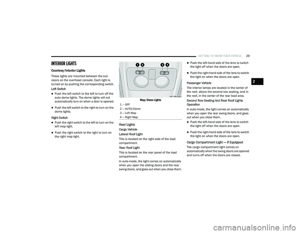
These lights are mounted between the sun
visors on the overhead console. Each light is
turned on by pushing the corresponding switch.
Left Switch
Push the left switch to the left to turn off the
auto dome lights. The dome lights will not
automatically turn on when a door is opened.
Push the left switch to the right to turn on the
dome lights.
Right Switch
Push the right switch to the left to turn on the
left map light.
Push the right switch to the right to turn on
the right map light.
Map/Dome Lights
Rear Lights
Cargo Vehicle
Lateral Roof Light
This is located on the right side of the load
compartment.
Rear Roof Light
This is located on the rear panel of the load
compartment.
In auto-mode, the light comes on automatically
when you open the sliding doors and the rear
swing doors, and goes out when you close them.
Push the left-hand side of the lens to switch
the light off when the doors are open.
Push the right-hand side of the lens to switch
the light on when the doors are open.
Passenger Vehicle
The interior lamps are located in the center of
the roof, above the second row seating, and in
the roof, in the center of the rear load area.
Second Row Seating And Rear Roof Lights
Operation
In auto-mode, the light comes on automatically
when you open the rear swing doors, and goes
out when you close them.
Push the left-hand side of the lens to switch
the light off when the doors are open.
Push the right-hand side of the lens to switch
the light on when the doors are open.
Cargo Compartment Light — If Equipped
The cargo compartment light comes on
automatically when the swing doors are opened
and turns off when the doors are closed.
1 — OFF
2 — AUTO/Dome
3 — Left Map
4 — Right Map
2
21_VM_OM_EN_USC_t.book Page 29
Page 43 of 280
GETTING TO KNOW YOUR VEHICLE41
(Continued)
(Continued)
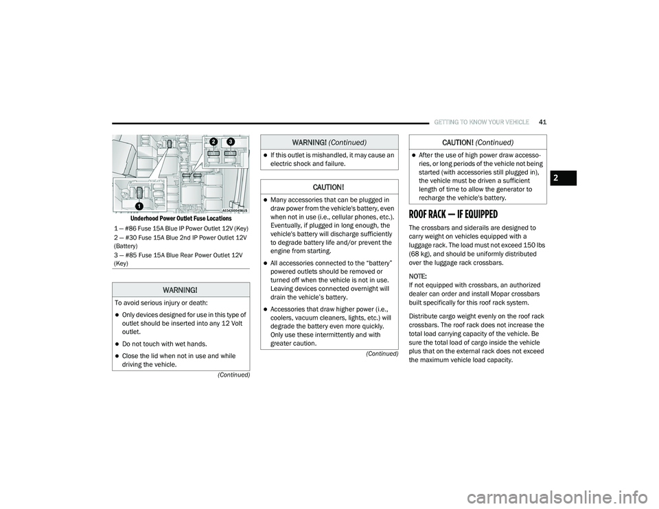
Underhood Power Outlet Fuse Locations
ROOF RACK — IF EQUIPPED
The crossbars and siderails are designed to
carry weight on vehicles equipped with a
luggage rack. The load must not exceed 150 lbs
(68 kg), and should be uniformly distributed
over the luggage rack crossbars.
NOTE:
If not equipped with crossbars, an authorized
dealer can order and install Mopar crossbars
built specifically for this roof rack system.
Distribute cargo weight evenly on the roof rack
crossbars. The roof rack does not increase the
total load carrying capacity of the vehicle. Be
sure the total load of cargo inside the vehicle
plus that on the external rack does not exceed
the maximum vehicle load capacity.1 — #86 Fuse 15A Blue IP Power Outlet 12V (Key)
2 — #30 Fuse 15A Blue 2nd IP Power Outlet 12V
(Battery)
3 — #85 Fuse 15A Blue Rear Power Outlet 12V
(Key)
WARNING!
To avoid serious injury or death:
Only devices designed for use in this type of
outlet should be inserted into any 12 Volt
outlet.
Do not touch with wet hands.
Close the lid when not in use and while
driving the vehicle.
If this outlet is mishandled, it may cause an
electric shock and failure.
CAUTION!
Many accessories that can be plugged in
draw power from the vehicle's battery, even
when not in use (i.e., cellular phones, etc.).
Eventually, if plugged in long enough, the
vehicle's battery will discharge sufficiently
to degrade battery life and/or prevent the
engine from starting.
All accessories connected to the “battery”
powered outlets should be removed or
turned off when the vehicle is not in use.
Leaving devices connected overnight will
drain the vehicle’s battery.
Accessories that draw higher power (i.e.,
coolers, vacuum cleaners, lights, etc.) will
degrade the battery even more quickly.
Only use these intermittently and with
greater caution.
WARNING! (Continued)
After the use of high power draw accesso -
ries, or long periods of the vehicle not being
started (with accessories still plugged in),
the vehicle must be driven a sufficient
length of time to allow the generator to
recharge the vehicle's battery.
CAUTION! (Continued)
2
21_VM_OM_EN_USC_t.book Page 41
Page 44 of 280
42GETTING TO KNOW YOUR VEHICLE
(Continued)
To move the crossbars, loosen the
attachments, located at the upper edge of each
crossbar, approximately eight turns using the
anti-theft wrench provided with the Mopar
crossbars. Then, move the crossbar to the
desired position, keeping the crossbars parallel
to the rack frame. Once the crossbar is in the
desired position, re-tighten it with the wrench to
lock the crossbar into position.
NOTE:
To help control wind noise when the cross-
bars are not in use, place the front and rear
crossbars approximately 24 inches (61 cm)
apart. Optimal noise reduction can then be
achieved by adjusting the front crossbar
forward or aft using increments of 1 inch
(2.5 cm).
If the crossbar (or any metallic object) is
placed over the satellite radio antenna (if
equipped), you may experience interruption
of satellite radio reception. For improved
satellite radio reception, avoid placing the
rear crossbar over the satellite radio
antenna.
WARNING!
Cargo must be securely tied down before
driving your vehicle. Improperly secured loads
can fly off the vehicle, particularly at high
speeds, resulting in personal injury or
property damage. Follow the roof rack
cautions when carrying cargo on your roof
rack.
CAUTION!
To prevent damage to the roof of your
vehicle, DO NOT carry any loads on the roof
rack without the crossbars deployed. The
load should be secured and placed on top
of the crossbars, not directly on the roof. If
it is necessary to place the load on the roof,
place a blanket or other protective layer
between the load and the roof surface.
To avoid damage to the roof rack and
vehicle, do not exceed the maximum roof
rack load capacity of 150 lb (68 kg). Always
distribute heavy loads as evenly as possible
and secure the load appropriately.
Loads should always be secured to cross -
bars first, with tie down loops used as addi -
tional securing points if needed. Tie loops
are intended as supplementary tie down
points only. Do not use ratcheting mecha -
nisms with the tie loops. Check the straps
and thumb wheels frequently to be sure
that the load remains securely attached.
Long loads that extend over the windshield,
such as wood panels or surfboards, or
loads with large frontal area should be
secured to both the front and rear of the
vehicle.
Travel at reduced speeds and turn corners
carefully when carrying large or heavy loads
on the roof rack. Wind forces, due to
natural causes or nearby truck traffic, can
add sudden upward lift to a load. This is
especially true on large flat loads and may
result in damage to the cargo or your
vehicle.
CAUTION! (Continued)
21_VM_OM_EN_USC_t.book Page 42
Page 144 of 280
142MULTIMEDIA
STEERING WHEEL AUDIO CONTROLS — IF
EQUIPPED
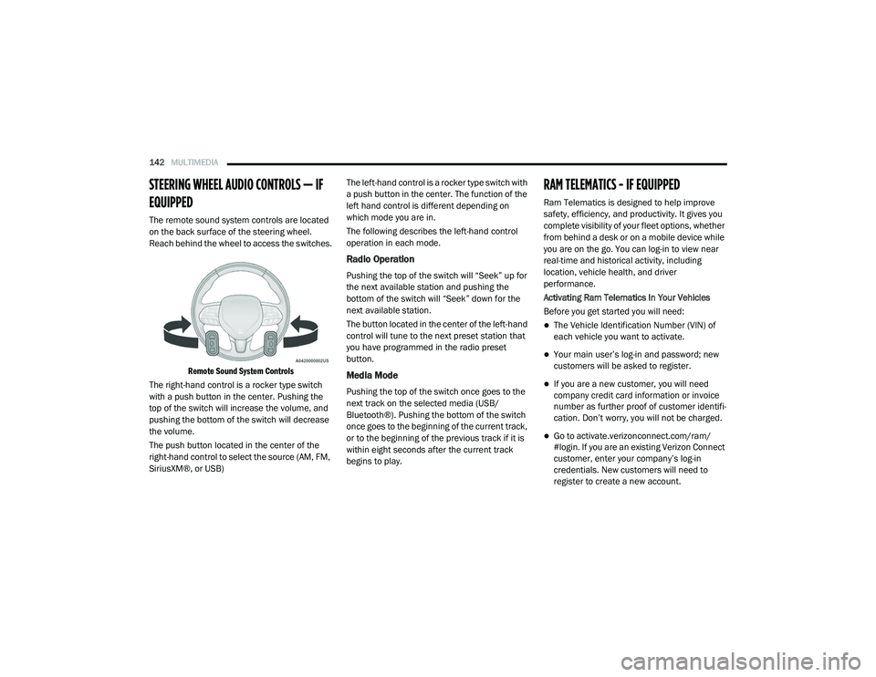
The remote sound system controls are located
on the back surface of the steering wheel.
Reach behind the wheel to access the switches.
Remote Sound System Controls
The right-hand control is a rocker type switch
with a push button in the center. Pushing the
top of the switch will increase the volume, and
pushing the bottom of the switch will decrease
the volume.
The push button located in the center of the
right-hand control to select the source (AM, FM,
SiriusXM®, or USB) The left-hand control is a rocker type switch with
a push button in the center. The function of the
left hand control is different depending on
which mode you are in.
The following describes the left-hand control
operation in each mode.
Radio Operation
Pushing the top of the switch will “Seek” up for
the next available station and pushing the
bottom of the switch will “Seek” down for the
next available station.
The button located in the center of the left-hand
control will tune to the next preset station that
you have programmed in the radio preset
button.
Media Mode
Pushing the top of the switch once goes to the
next track on the selected media (USB/
Bluetooth®). Pushing the bottom of the switch
once goes to the beginning of the current track,
or to the beginning of the previous track if it is
within eight seconds after the current track
begins to play.
RAM TELEMATICS - IF EQUIPPED
Ram Telematics is designed to help improve
safety, efficiency, and productivity. It gives you
complete visibility of your fleet options, whether
from behind a desk or on a mobile device while
you are on the go. You can log-in to view near
real-time and historical activity, including
location, vehicle health, and driver
performance.
Activating Ram Telematics In Your Vehicles
Before you get started you will need:
The Vehicle Identification Number (VIN) of
each vehicle you want to activate.
Your main user’s log-in and password; new
customers will be asked to register.
If you are a new customer, you will need
company credit card information or invoice
number as further proof of customer identifi
-
cation. Don’t worry, you will not be charged.
Go to activate.verizonconnect.com/ram/
#login. If you are an existing Verizon Connect
customer, enter your company’s log-in
credentials. New customers will need to
register to create a new account.
21_VM_OM_EN_USC_t.book Page 142
Page 167 of 280

SAFETY165
Supplemental Side Air Bag Inflatable Curtains
(SABICs)
This vehicle is equipped with Supplemental
Side Air Bag Inflatable Curtains (SABICs).
Supplemental Side Air Bag Inflatable Curtains
(SABICs) are located above the side windows.
The trim covering the SABICs is labeled “SRS
AIRBAG” or “AIRBAG.”
Supplemental Side Air Bag Inflatable Curtain (SABIC) Label Location
SABICs may help reduce the risk of head and
other injuries to front and rear seat outboard
occupants in certain side impacts, in addition to
the injury reduction potential provided by the
seat belts and body structure.
The SABIC deploys downward, covering the side
windows. An inflating SABIC pushes the outside edge of the headliner out of the way and covers
the window. The SABICs inflate with enough
force to injure occupants if they are not belted
and seated properly, or if items are positioned
in the area where the SABICs inflate. Children
are at an even greater risk of injury from a
deploying air bag.
The SABICs may help reduce the risk of partial
or complete ejection of vehicle occupants
through side windows in certain side impact
events.
Side Impacts
The Side Air Bags are designed to activate in
certain side impacts. The Occupant Restraint
Controller (ORC) determines whether the
deployment of the Side Air Bags in a particular
impact event is appropriate, based on the
severity and type of collision. The side impact
sensors aid the ORC in determining the
appropriate response to impact events. The
system is calibrated to deploy the Side Air Bags
on the impact side of the vehicle during impacts
that require Side Air Bag occupant protection. In
side impacts, the Side Air Bags deploy
independently; a left side impact deploys the
left Side Air Bags only and a right-side impact
deploys the right Side Air Bags only. Vehicle
damage by itself is not a good indicator of
whether or not Side Air Bags should have
deployed.
The Side Air Bags will not deploy in all side
collisions, including some collisions at certain
angles, or some side collisions that do not
impact the area of the passenger compartment.
The Side Air Bags may deploy during angled or
offset frontal collisions where the front air bags
deploy.
WARNING!
Do not mount equipment, or stack luggage
or other cargo up high enough to block the
deployment of the SABICs. The trim
covering above the side windows where the
SABIC and its deployment path are located
should remain free from any obstructions.
In order for the SABICs to work as intended,
do not install any accessory items in your
vehicle which could alter the roof. Do not
add an aftermarket sunroof to your vehicle.
Do not add roof racks that require perma
-
nent attachments (bolts or screws) for
installation on the vehicle roof. Do not drill
into the roof of the vehicle for any reason.
6
21_VM_OM_EN_USC_t.book Page 165
Page 217 of 280
IN CASE OF EMERGENCY215
Front/Rear Side Marker Lamps
See below steps to replace:
The front/rear side marker lamps are LED and
not serviced separately. See an authorized
dealer for replacement of these lights.
Rear Tail, Stop, Backup And Turn Signal
Lamps
The rear light clusters contain taillight, brake
light, direction indicator and reverse/rear fog
light bulbs. To access the light clusters, see
below steps to replace:
1. Open the rear doors.
2. Remove the screws and remove the tail
lamp assembly.
3. Remove the screws and separate the backplate from the lamp housing.
4. Remove the tail, stop, or turn signal bulbs by pushing them slightly and turning counter -
clockwise.
5. Remove the backup lamp bulb by pulling straight out.
6. Replace lamps as required and reinstall lamp. The bulbs are arranged inside the light cluster
as follows:
Third Brake Light (Center Mount)
See below steps to replace:
1. For versions with tailgate, loosen the two
fastening screws and extract the cluster.
2. For versions with swing doors, remove rubber plugs, remove retaining tabs and
extract the cluster.
3. For versions with high roof and swing doors, remove the pressure-fit plastic guard and
rubber cap using a screwdriver, release the
retaining tags as shown in the figure and
remove the unit.
4. Remove the appropriate tabs and remove the bulb holder.
5. Remove the snap-fitted bulb and replace it.
License Plate Lights
See below steps to replace:
1. Disengage the holding tabs and remove the lens by lifting to the left.
2. Remove the bulbs by releasing them from the side contacts; insert the new bulbs and
make sure they are correctly clamped
between these contacts.
Replacing Interior Bulbs
Dome Lamp With Spot Lights
See below steps to replace:
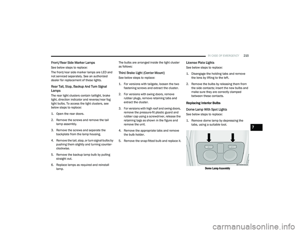
1. Remove dome lamp by depressing the tabs, using a suitable tool.
Dome Lamp Assembly
7
21_VM_OM_EN_USC_t.book Page 215
Page 218 of 280

216IN CASE OF EMERGENCY
2. Open protective cover.
Dome Lamp
3. Replace the bulbs releasing them from the side contacts making sure that the new
bulbs are correctly secured between the
contacts.
4. Close the protective cover and reposition it back into its housing, making sure that it
locks into place.
Rear Roof Lamp
See below steps to replace:
1. Remove roof lamp by depressing the tabs, using a suitable tool.
Roof Lamp
2. Open the cover.
Roof Lamp (Reverse Side)
3. Replace the bulb releasing them from the
side contacts making sure that the new
bulbs are correctly secured between the
contacts.
Roof Lamp (Reverse Side)
4. Close the protective cover and reposition it back into its housing, making sure that it
locks into place.
1 — Protective Cover
2 — Bulbs
1 — Cover
1 — Bulb
21_VM_OM_EN_USC_t.book Page 216