2021 RAM PROMASTER CITY stop start
[x] Cancel search: stop startPage 150 of 280
148SAFETY
The ESC Activation/Malfunction Indicator Light
(located in the instrument cluster) starts to
flash as soon as the tires lose traction and the
ESC system becomes active. The ESC
Activation/Malfunction Indicator Light also
flashes when TCS is active. If the ESC
Activation/Malfunction Indicator Light begins to
flash during acceleration, ease up on the
accelerator and apply as little throttle as
possible. Be sure to adapt your speed and
driving to the prevailing road conditions.
The ESC OFF Indicator Light indicates
the Electronic Stability Control (ESC)
is in a reduced mode.
NOTE:
The ESC Activation/Malfunction Indicator
Light and the ESC OFF Indicator Light come
on momentarily each time the ignition switch
placed in the ON position.
Each time the ignition is placed in the ON
position, the ESC system will be on even if it
was turned off previously.
Electronic Roll Mitigation (ERM)
ERM anticipates the potential for wheel lift by
monitoring the driver’s steering wheel input and
the speed of the vehicle. When ERM determines
that the rate of change of the steering wheel
angle and vehicle’s speed are sufficient to
potentially cause wheel lift, it then applies the
appropriate brake and may also reduce engine
power to lessen the chance that wheel lift will
occur.
ERM can only reduce the chance of wheel lift
occurring during severe or evasive driving
maneuvers; it cannot prevent wheel lift due to
other factors, such as road conditions, leaving
the roadway, or striking objects or other
vehicles.
Hill Start Assist (HSA)
HSA is designed to assist the driver when
starting a vehicle from a stop on a hill. HSA will
maintain the level of brake pressure the driver
applied for a short period of time after the driver
takes their foot off of the brake pedal. If the
driver does not apply the throttle during this
short period of time, the system will release
brake pressure and the vehicle will roll down the
hill. The system will release brake pressure in
proportion to the amount of throttle applied as
the vehicle starts to move in the intended
direction of travel.
HSA Activation Criteria
The following criteria must be met in order for
HSA to activate:
The vehicle must be stopped.
The vehicle must be on a 5% (approximate)
grade or greater hill.
Gear selection matches vehicle uphill direc -
tion (i.e., vehicle facing uphill is in forward
gear; vehicle backing uphill is in REVERSE
gear).
WARNING!
Many factors, such as vehicle loading, road
conditions and driving conditions, influence
the chance that wheel lift or rollover may
occur. ERM cannot prevent all wheel lift or roll
overs, especially those that involve leaving
the roadway or striking objects or other vehi -
cles. The capabilities of an ERM-equipped
vehicle must never be exploited in a reckless
or dangerous manner which could jeopardize
the user's safety or the safety of others.
21_VM_OM_EN_USC_t.book Page 148
Page 163 of 280

SAFETY161
Supplemental Restraint Systems (SRS)
Some of the safety features described in this
section may be standard equipment on some
models, or may be optional equipment on
others. If you are not sure, ask an authorized
dealer.
The air bag system must be ready to protect you
in a collision. The Occupant Restraint Controller
(ORC) monitors the internal circuits and
interconnecting wiring associated with the
electrical Air Bag System Components. Your
vehicle may be equipped with the following Air
Bag System Components:
Air Bag System Components
Occupant Restraint Controller (ORC)
Air Bag Warning Light
Steering Wheel and Column
Instrument Panel
Knee Impact Bolsters
Driver and Front Passenger Air Bags
Seat Belt Buckle Switch
Supplemental Side Air Bags
Supplemental Knee Air Bags
Front and Side Impact Sensors
Seat Belt Pretensioners
Air Bag Warning Light
The Occupant Restraint Controller
(ORC) monitors the readiness of the
electronic parts of the air bag system
whenever the ignition switch is in the
AVV/START or MAR/ACC/ON/RUN position. If
the ignition switch is in the STOP/OFF/LOCK
position the air bag system is not on and the air
bags will not inflate. The ORC contains a backup power supply
system that may deploy the air bag system even
if the battery loses power or it becomes
disconnected prior to deployment.
The ORC turns on the Air Bag Warning Light in
the instrument panel for approximately four to
eight seconds for a self-check when the ignition
switch is in the MAR/ACC/ON/RUN position.
After the self-check, the Air Bag Warning Light
will turn off. If the ORC detects a malfunction in
any part of the system, it turns on the Air Bag
Warning Light, either momentarily or
continuously. A single chime will sound to alert
you if the light comes on again after initial
startup.
The ORC also includes diagnostics that will
illuminate the instrument panel Air Bag Warning
Light if a malfunction is detected that could
affect the air bag system. The diagnostics also
record the nature of the malfunction. While the
air bag system is designed to be maintenance
free, if any of the following occurs, have an
authorized dealer service the air bag system
immediately.
Failure to replace the seat belt assembly
could increase the risk of injury in colli
-
sions.
Do not use the Automatic Locking Mode to
restrain occupants who are wearing the
seat belt or children who are using booster
seats. The locked mode is only used to
install rear-facing or forward-facing child
restraints that have a harness for
restraining the child.
WARNING! (Continued)
6
21_VM_OM_EN_USC_t.book Page 161
Page 170 of 280

168SAFETY
Enhanced Accident Response System
In the event of an impact, if the communication
network remains intact, and the power remains
intact, depending on the nature of the event,
the Occupant Restraint Controller (ORC) will
determine whether to have the Enhanced
Accident Response System perform the
following functions:
Cut off fuel to the engine (if equipped)
Cut off battery power to the electric motor (if
equipped)
Flash hazard lights as long as the battery has
power
Turn on the interior lights, which remain on
as long as the battery has power or for
15 minutes from the intervention of the
Enhanced Accident Response System
Unlock the power door locks
Your vehicle may also be designed to perform
any of these other functions in response to the
Enhanced Accident Response System:
Turn off the Fuel Filter Heater, Turn off the
HVAC Blower Motor, Close the HVAC Circula -
tion Door
Cut off battery power to the:
Engine
Electric Motor (if equipped)
Electric Power Steering
Brake booster
Electric park brake
Automatic transmission gear selector
Horn
Front wiper
Headlamp washer pump
NOTE:
After an accident, remember to cycle the igni -
tion to the STOP/OFF position and remove the
key from the ignition switch to avoid draining
the battery. Carefully check the vehicle for fuel
leaks in the engine compartment and on the
ground near the engine compartment and fuel
tank before resetting the system and starting
the engine. If there are no fuel leaks or damage
to the vehicle electrical devices (e.g. headlights)
after an accident, reset the system by following
the procedure described below. If you have any
doubt, contact an authorized dealer.
Enhanced Accident Response System Reset
Procedure
In order to reset the Enhanced Accident
Response System functions after an event, the
ignition switch must be changed from ignition
AVV/START or MAR/RUN to ignition STOP/OFF.
Carefully check the vehicle for fuel leaks in the
engine compartment and on the ground near
the engine compartment and fuel tank before
resetting the system and starting the engine.
After a crash, if the vehicle will not start after
performing the reset procedure, the vehicle
must be towed to an authorized dealer to be
inspected and to have the Enhanced Accident
Response System reset.
21_VM_OM_EN_USC_t.book Page 168
Page 205 of 280
IN CASE OF EMERGENCY203
(Continued)
Insert the power plug into the vehicle power
outlet socket. Start the vehicle engine.
Push the Tire Service Kit power button on. The
electric compressor will be turned on, sealant
and air will inflate the tire.
Minimum 26 psi (1.8 bar) of pressure should be
reached within 20 minutes. If the pressure has
not been reached, turn off and remove the Tire
Service Kit, drive the vehicle 30 feet
(10 meters) back and forth, to better distribute
the sealant inside the tire.
Attach the clear flexible filling tube of the
compressor directly to the tire valve and repeat
the inflation process.
When the correct pressure has been reached,
start driving the vehicle to uniformly distribute
the sealant inside the tire. After 10 minutes,
stop and check the tire pressure. If the pressure
is below 19 psi (1.3 bar), do not drive the
vehicle, as the tire is too damaged, contact the
nearest authorized dealer.WARNING!
Do not attempt to seal a tire on the side of
the vehicle closest to traffic. Pull far enough
off the road to avoid the danger of being hit
when using the Tire Service Kit.
Do not use Tire Service Kit or drive the
vehicle under the following circumstances:
If the puncture in the tire tread is
approximately 1/4 inch (6 mm) or
larger.
If the tire has any sidewall damage.
If the tire has any damage from driving
with extremely low tire pressure.
If the tire has any damage from driving
on a flat tire.
If the wheel has any damage.
If you are unsure of the condition of the
tire or the wheel.
Keep Tire Service Kit away from open
flames or heat source.
A loose Tire Service Kit thrown forward in a
collision or hard stop could endanger the
occupants of the vehicle. Always stow the
Tire Service Kit in the place provided.
Failure to follow these warnings can result
in injuries that are serious or fatal to you,
your passengers, and others around you.
Take care not to allow the contents of Tire
Service Kit to come in contact with hair,
eyes, or clothing. Tire Service Kit sealant is
harmful if inhaled, swallowed, or absorbed
through the skin. It causes skin, eye, and
respiratory irritation. Flush immediately
with plenty of water if there is any contact
with eyes or skin. Change clothing as soon
as possible, if there is any contact with
clothing.
Tire Service Kit Sealant solution contains
latex. In case of an allergic reaction or rash,
consult a physician immediately. Keep Tire
Service Kit out of reach of children. If swal -
lowed, rinse mouth immediately with plenty
of water and drink plenty of water. Do not
induce vomiting! Consult a physician imme -
diately.
WARNING! (Continued)
7
21_VM_OM_EN_USC_t.book Page 203
Page 208 of 280
206IN CASE OF EMERGENCY
See below steps to prepare for jump starting:
1. Apply the parking brake, shift the
automatic transmission into PARK (P) and
turn the ignition to STOP.
2. Turn off the heater, radio, and all electrical accessories.
3. If using another vehicle to jump-start the battery, park the vehicle within the jumper
cables reach, apply the parking brake and
make sure the ignition is OFF.
Jump Starting Procedure
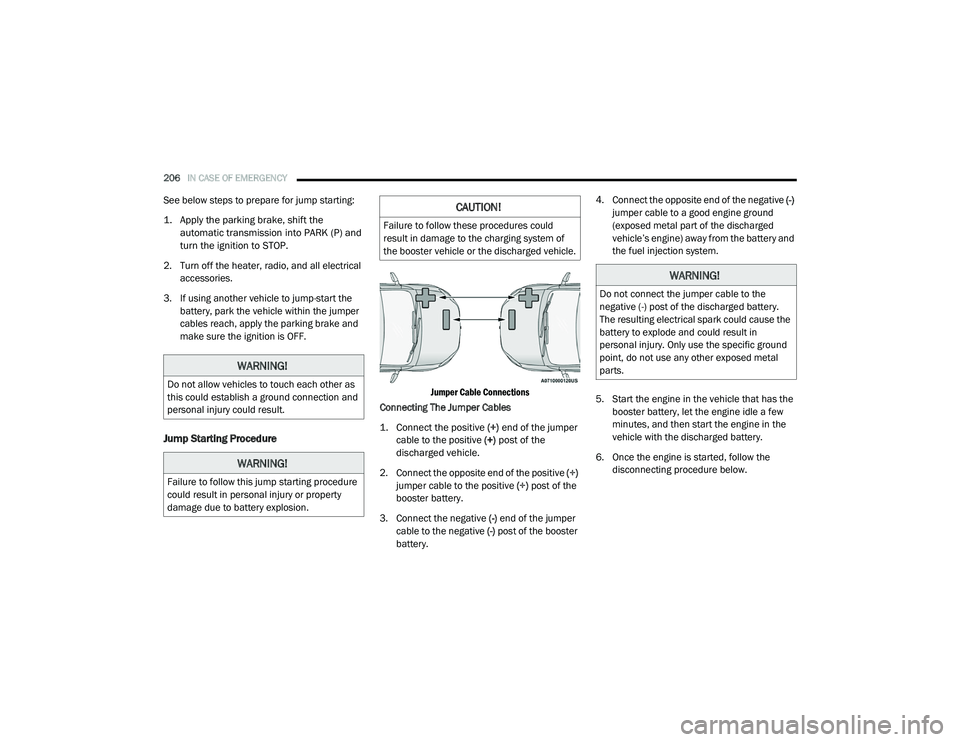
Jumper Cable Connections
Connecting The Jumper Cables
1. Connect the positive
(+) end of the jumper
cable to the positive (+)
post of the
discharged vehicle.
2. Connect the opposite end of the positive (+)
jumper cable to the positive (+) post of the
booster battery.
3. Connect the negative (-) end of the jumper
cable to the negative (-) post of the booster
battery. 4. Connect the opposite end of the negative
(-)
jumper cable to a good engine ground
(exposed metal part of the discharged
vehicle’s engine) away from the battery and
the fuel injection system.
5. Start the engine in the vehicle that has the booster battery, let the engine idle a few
minutes, and then start the engine in the
vehicle with the discharged battery.
6. Once the engine is started, follow the disconnecting procedure below.
WARNING!
Do not allow vehicles to touch each other as
this could establish a ground connection and
personal injury could result.
WARNING!
Failure to follow this jump starting procedure
could result in personal injury or property
damage due to battery explosion.
CAUTION!
Failure to follow these procedures could
result in damage to the charging system of
the booster vehicle or the discharged vehicle.
WARNING!
Do not connect the jumper cable to the
negative (-) post of the discharged battery.
The resulting electrical spark could cause the
battery to explode and could result in
personal injury. Only use the specific ground
point, do not use any other exposed metal
parts.
21_VM_OM_EN_USC_t.book Page 206
Page 209 of 280

IN CASE OF EMERGENCY207
Disconnecting The Jumper Cables
1. Disconnect the negative
(-)
end of the
jumper cable from the engine ground of
the vehicle with the discharged battery.
2. Disconnect the opposite end of the negative (-) jumper cable from the
negative (-) post of the booster battery.
3. Disconnect the positive (+) end of the
jumper cable from the positive (+) post of
the booster battery.
4. Disconnect the opposite end of the positive (+) jumper cable from the
positive (+) post of the vehicle with the
discharged battery.
If frequent jump starting is required to start your
vehicle you should have the battery and
charging system inspected at an authorized
dealer.
IF YOUR ENGINE OVERHEATS
If the vehicle is overheating, it will need to be
serviced by an authorized dealer.
In any of the following situations, you can
reduce the potential for overheating by taking
the appropriate action.
On the highways — slow down.
In city traffic — while stopped, place the trans -
mission in NEUTRAL (N), but do not increase
the engine idle speed while preventing
vehicle motion with the brakes. NOTE:
There are steps that you can take to slow down
an impending overheat condition:
If your Air Conditioner (A/C) is on, turn it off.
The A/C system adds heat to the engine
cooling system and turning the A/C off can
help remove this heat.
You can also turn the temperature control to
maximum heat, the mode control to floor and
the blower control to high. This allows the
heater core to act as a supplement to the
radiator and aids in removing heat from the
engine cooling system.
CAUTION!
Accessories plugged into the vehicle power
outlets draw power from the vehicle’s battery,
even when not in use (i.e., cellular devices,
etc.). Eventually, if plugged in long enough
without engine operation, the vehicle’s
battery will discharge sufficiently to degrade
battery life and/or prevent the engine from
starting.
WARNING!
You or others can be badly burned by hot
engine coolant (antifreeze) or steam from
your radiator. If you see or hear steam coming
from under the hood, do not open the hood
until the radiator has had time to cool. Never
try to open a cooling system pressure cap
when the radiator or coolant bottle is hot.7
21_VM_OM_EN_USC_t.book Page 207
Page 228 of 280
226SERVICING AND MAINTENANCE
Avoid using the wiper blades to remove frost or
ice from the windshield. Keep the blade rubber
out of contact with petroleum products such as
engine oil, gasoline, etc.
NOTE:
Life expectancy of wiper blades varies
depending on geographical area and frequency
of use. If chattering, marks, water lines or wet
spots are present, clean the wiper blades or
replace as necessary.
Wiper Service Position
If it is necessary to lift the blade from the
windshield (In the event of snow or blade
replacement) proceed as directed:
1. Rotate the end of the multifunction lever to
the OFF position.
2. Turn the ignition to the MAR (ON/RUN) position then to STOP.
3. After turning the ignition to the STOP, within two minutes move the right stalk upward,
into the unstable (“anti-panic”) position, for
at least half of a second. The windshield
wiper then executes part of a stroke; at
each command, approximately 1/3 of a
normal wiper stroke is triggered. NOTE:
The previous operation can be repeated up to
three times in order to move the blades to the
most suitable position.
4. Lift the blade from the windshield and
proceed with the required operation.
5. Carefully lower the blade, bringing it back in contact with the windshield.
6. Bring the blade to the initial rest position, turning the ignition to MAR (ON/RUN).
NOTE:
Do not operate the wiper with the blades lifted
from the windshield.
Exhaust System
The best protection against carbon monoxide
entry into the vehicle body is a properly
maintained engine exhaust system.
If you notice a change in the sound of the
exhaust system; or if the exhaust fumes can be
detected inside the vehicle; or when the
underside or rear of the vehicle is damaged;
have an authorized technician inspect the
complete exhaust system and adjacent body
areas for broken, damaged, deteriorated, or mispositioned parts. Open seams or loose
connections could permit exhaust fumes to
seep into the passenger compartment. In
addition, have the exhaust system inspected
each time the vehicle is raised for lubrication or
oil change. Replace as required.
WARNING!
Exhaust gases can injure or kill. They
contain carbon monoxide (CO), which is
colorless and odorless. Breathing it can
make you unconscious and can eventually
poison you Ú
page 185.
A hot exhaust system can start a fire if you
park over materials that can burn. Such
materials might be grass or leaves coming
into contact with your exhaust system. Do
not park or operate your vehicle in areas
where your exhaust system can contact
anything that can burn.
21_VM_OM_EN_USC_t.book Page 226
Page 229 of 280
SERVICING AND MAINTENANCE227
Under normal operating conditions, the
catalytic converter will not require
maintenance. However, it is important to keep
the engine properly tuned to ensure proper
catalyst operation and prevent possible catalyst
damage. NOTE:
Intentional tampering with emissions control
systems can result in civil penalties being
assessed against you.
In unusual situations involving grossly
malfunctioning engine operation, a scorching
odor may suggest severe and abnormal catalyst
overheating. If this occurs, stop the vehicle, turn
off the engine and allow it to cool. Service,
including a tune-up to manufacturer's
specifications, should be obtained immediately.
To minimize the possibility of catalytic converter
damage:
Do not interrupt the ignition when the trans
-
mission is in gear and the vehicle is in
motion.
Do not try to start the vehicle by pushing or
towing the vehicle.
Do not idle the engine with any ignition
components disconnected or removed, such
as when diagnostic testing, or for prolonged
periods during very rough idle or malfunc -
tioning operating conditions.
Cooling System CAUTION!
The catalytic converter requires the use of
unleaded fuel only. Leaded gasoline will
destroy the effectiveness of the catalyst as
an emissions control device and may seri -
ously reduce engine performance and
cause serious damage to the engine.
Damage to the catalytic converter can
result if your vehicle is not kept in proper
operating condition. In the event of engine
malfunction, particularly involving engine
misfire or other apparent loss of perfor -
mance, have your vehicle serviced
promptly. Continued operation of your
vehicle with a severe malfunction could
cause the converter to overheat, resulting
in possible damage to the converter and
vehicle.
WARNING!
You or others can be badly burned by hot
engine coolant (antifreeze) or steam from
your radiator. If you see or hear steam
coming from under the hood, do not open
the hood until the radiator has had time to
cool. Never open a cooling system pressure
cap when the radiator or coolant bottle is
hot.
Keep hands, tools, clothing, and jewelry
away from the radiator cooling fan when
the hood is raised. The fan starts automati -
cally and may start at any time, whether the
engine is running or not.
When working near the radiator cooling fan,
disconnect the fan motor lead or turn the
ignition to the OFF mode. The fan is
temperature controlled and can start at any
time the ignition is in the ON mode.
8
21_VM_OM_EN_USC_t.book Page 227