2021 RAM PROMASTER CITY instrument cluster
[x] Cancel search: instrument clusterPage 74 of 280

72STARTING AND OPERATING
(Continued)
ParkSense Rear Park Assist Failure
Indications
A malfunction of the ParkSense sensors or
system is indicated, during REVERSE gear
engagement, by the instrument panel warning
icon.The warning icon is illuminated and a
message is displayed on the
instrument cluster display (if
equipped) Ú page 49.
The sensors and wiring are tested continuously
when the ignition is in the MAR (ACC/ON/RUN)
position. Failures are indicated immediately if
they occur when the system is on.
Even if the system is able to identify that a
specific sensor is in failure condition, the
instrument cluster display shall indicate that
the ParkSense system is unavailable, without
reference to the sensor in failure condition. If
even a single sensor fails, the entire system will
be disabled. The system is turned off
automatically.
Cleaning The ParkSense Rear Park Assist
System
Clean the ParkSense sensors with water, car
wash soap and a soft cloth. Do not use rough or
hard cloths. In washing stations, clean sensors
quickly while keeping the vapor jet/high
pressure washing nozzles at least 4 inches
(10 cm) from the sensors. Do not scratch or
poke the sensors. Otherwise, you could damage
the sensors.
ParkSense Rear Park Assist System Usage
Precautions
NOTE:
Ensure that the outer surface and the under -
side of the rear fascia/bumper is clean and
clear of snow, ice, mud, dirt or other obstruc -
tion to keep the ParkSense Rear Park Assist
system operating properly.
Jackhammers, large trucks, and other vibra -
tions could affect the performance of the
ParkSense system.
Clean the ParkSense sensors regularly,
taking care not to scratch or damage them.
The sensors must not be covered with ice,
snow, slush, mud, dirt or debris. Failure to do so can result in the system not working prop
-
erly. The ParkSense system might not detect
an obstacle behind the fascia/bumper, or it
could provide a false indication that an
obstacle is behind the fascia/bumper.
Objects such as bicycle carriers, etc., must
not be placed within 12 inches (30 cm) from
the rear fascia/bumper while driving the
vehicle. Failure to do so can result in the
system misinterpreting a close object as a
sensor problem, causing a failure indication
to be displayed in the instrument cluster
display.
WARNING!
Drivers must be careful when backing up
even when using ParkSense. Always check
carefully behind your vehicle, look behind
you, and be sure to check for pedestrians,
animals, other vehicles, obstructions, and
blind spots before backing up. You are
responsible for safety and must continue to
pay attention to your surroundings. Failure
to do so can result in serious injury or
death.
21_VM_OM_EN_USC_t.book Page 72
Page 91 of 280
MULTIMEDIA89
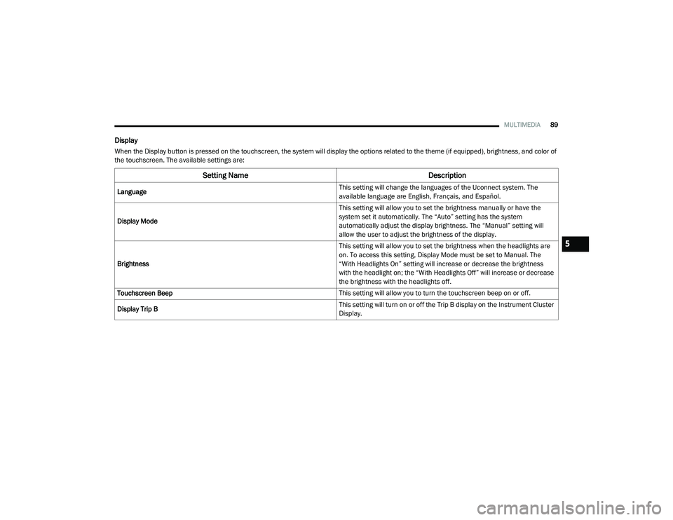
Display
When the Display button is pressed on the touchscreen, the system will display the options related to the theme (if equipped), brightness, and color of
the touchscreen. The available settings are:
Setting Name Description
Language This setting will change the languages of the Uconnect system. The
available language are English, Français, and Español.
Display Mode This setting will allow you to set the brightness manually or have the
system set it automatically. The “Auto” setting has the system
automatically adjust the display brightness. The “Manual” setting will
allow the user to adjust the brightness of the display.
Brightness This setting will allow you to set the brightness when the headlights are
on. To access this setting, Display Mode must be set to Manual. The
“With Headlights On” setting will increase or decrease the brightness
with the headlight on; the “With Headlights Off” will increase or decrease
the brightness with the headlights off.
Touchscreen Beep This setting will allow you to turn the touchscreen beep on or off.
Display Trip B This setting will turn on or off the Trip B display on the Instrument Cluster
Display.
5
21_VM_OM_EN_USC_t.book Page 89
Page 92 of 280
90MULTIMEDIA
Voice
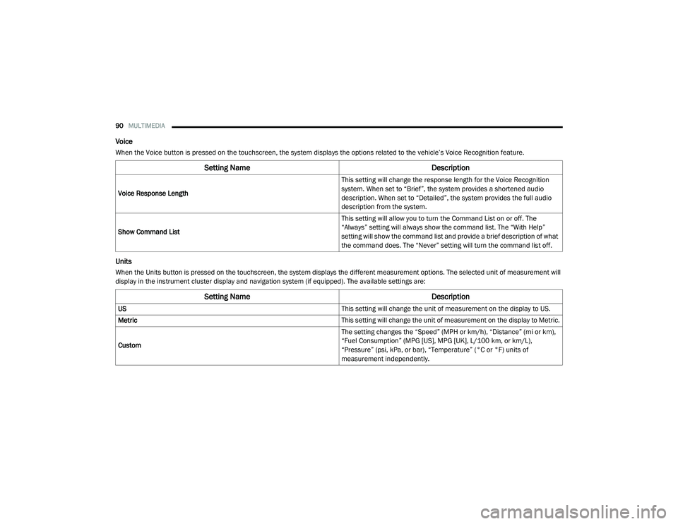
When the Voice button is pressed on the touchscreen, the system displays the options related to the vehicle’s Voice Recognition feature.
Units
When the Units button is pressed on the touchscreen, the system displays the different measurement options. The selected unit of measurement will
display in the instrument cluster display and navigation system (if equipped). The available settings are:
Setting Name Description
Voice Response Length This setting will change the response length for the Voice Recognition
system. When set to “Brief”, the system provides a shortened audio
description. When set to “Detailed”, the system provides the full audio
description from the system.
Show Command List This setting will allow you to turn the Command List on or off. The
“Always” setting will always show the command list. The “With Help”
setting will show the command list and provide a brief description of what
the command does. The “Never” setting will turn the command list off.
Setting Name
Description
US This setting will change the unit of measurement on the display to US.
Metric This setting will change the unit of measurement on the display to Metric.
Custom The setting changes the “Speed” (MPH or km/h), “Distance” (mi or km),
“Fuel Consumption” (MPG [US], MPG [UK], L/100 km, or km/L),
“Pressure” (psi, kPa, or bar), “Temperature” (°C or °F) units of
measurement independently.
21_VM_OM_EN_USC_t.book Page 90
Page 149 of 280
SAFETY147
(Continued)
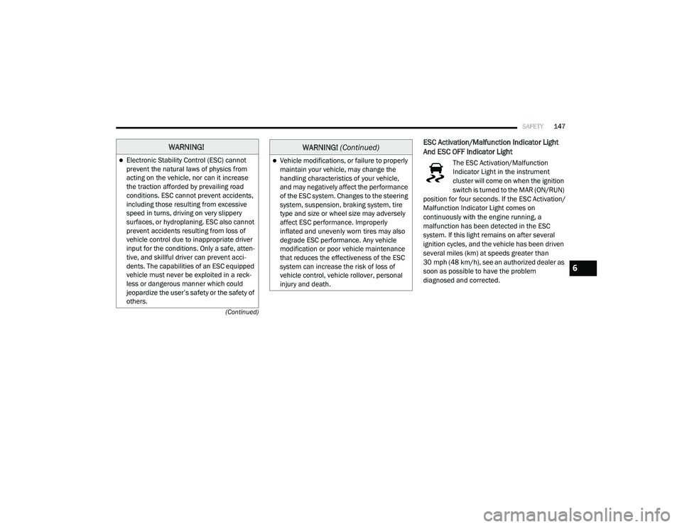
ESC Activation/Malfunction Indicator Light
And ESC OFF Indicator Light
The ESC Activation/Malfunction
Indicator Light in the instrument
cluster will come on when the ignition
switch is turned to the MAR (ON/RUN)
position for four seconds. If the ESC Activation/
Malfunction Indicator Light comes on
continuously with the engine running, a
malfunction has been detected in the ESC
system. If this light remains on after several
ignition cycles, and the vehicle has been driven
several miles (km) at speeds greater than
30 mph (48 km/h), see an authorized dealer as
soon as possible to have the problem
diagnosed and corrected.
WARNING!
Electronic Stability Control (ESC) cannot
prevent the natural laws of physics from
acting on the vehicle, nor can it increase
the traction afforded by prevailing road
conditions. ESC cannot prevent accidents,
including those resulting from excessive
speed in turns, driving on very slippery
surfaces, or hydroplaning. ESC also cannot
prevent accidents resulting from loss of
vehicle control due to inappropriate driver
input for the conditions. Only a safe, atten -
tive, and skillful driver can prevent acci -
dents. The capabilities of an ESC equipped
vehicle must never be exploited in a reck -
less or dangerous manner which could
jeopardize the user’s safety or the safety of
others.Vehicle modifications, or failure to properly
maintain your vehicle, may change the
handling characteristics of your vehicle,
and may negatively affect the performance
of the ESC system. Changes to the steering
system, suspension, braking system, tire
type and size or wheel size may adversely
affect ESC performance. Improperly
inflated and unevenly worn tires may also
degrade ESC performance. Any vehicle
modification or poor vehicle maintenance
that reduces the effectiveness of the ESC
system can increase the risk of loss of
vehicle control, vehicle rollover, personal
injury and death.
WARNING! (Continued)
6
21_VM_OM_EN_USC_t.book Page 147
Page 150 of 280
148SAFETY
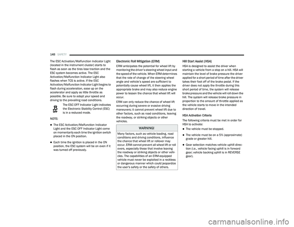
The ESC Activation/Malfunction Indicator Light
(located in the instrument cluster) starts to
flash as soon as the tires lose traction and the
ESC system becomes active. The ESC
Activation/Malfunction Indicator Light also
flashes when TCS is active. If the ESC
Activation/Malfunction Indicator Light begins to
flash during acceleration, ease up on the
accelerator and apply as little throttle as
possible. Be sure to adapt your speed and
driving to the prevailing road conditions.
The ESC OFF Indicator Light indicates
the Electronic Stability Control (ESC)
is in a reduced mode.
NOTE:
The ESC Activation/Malfunction Indicator
Light and the ESC OFF Indicator Light come
on momentarily each time the ignition switch
placed in the ON position.
Each time the ignition is placed in the ON
position, the ESC system will be on even if it
was turned off previously.
Electronic Roll Mitigation (ERM)
ERM anticipates the potential for wheel lift by
monitoring the driver’s steering wheel input and
the speed of the vehicle. When ERM determines
that the rate of change of the steering wheel
angle and vehicle’s speed are sufficient to
potentially cause wheel lift, it then applies the
appropriate brake and may also reduce engine
power to lessen the chance that wheel lift will
occur.
ERM can only reduce the chance of wheel lift
occurring during severe or evasive driving
maneuvers; it cannot prevent wheel lift due to
other factors, such as road conditions, leaving
the roadway, or striking objects or other
vehicles.
Hill Start Assist (HSA)
HSA is designed to assist the driver when
starting a vehicle from a stop on a hill. HSA will
maintain the level of brake pressure the driver
applied for a short period of time after the driver
takes their foot off of the brake pedal. If the
driver does not apply the throttle during this
short period of time, the system will release
brake pressure and the vehicle will roll down the
hill. The system will release brake pressure in
proportion to the amount of throttle applied as
the vehicle starts to move in the intended
direction of travel.
HSA Activation Criteria
The following criteria must be met in order for
HSA to activate:
The vehicle must be stopped.
The vehicle must be on a 5% (approximate)
grade or greater hill.
Gear selection matches vehicle uphill direc -
tion (i.e., vehicle facing uphill is in forward
gear; vehicle backing uphill is in REVERSE
gear).
WARNING!
Many factors, such as vehicle loading, road
conditions and driving conditions, influence
the chance that wheel lift or rollover may
occur. ERM cannot prevent all wheel lift or roll
overs, especially those that involve leaving
the roadway or striking objects or other vehi -
cles. The capabilities of an ERM-equipped
vehicle must never be exploited in a reckless
or dangerous manner which could jeopardize
the user's safety or the safety of others.
21_VM_OM_EN_USC_t.book Page 148
Page 153 of 280

SAFETY151
NOTE:
The TPMS is not intended to replace normal
tire care and maintenance or to provide
warning of a tire failure or condition.
The TPMS should not be used as a tire pres -
sure gauge while adjusting your tire pressure.
Driving on a significantly under-inflated tire
causes the tire to overheat and can lead to
tire failure. Under-inflation also reduces fuel
efficiency and tire tread life, and may affect
the vehicle’s handling and stopping ability.
The TPMS is not a substitute for proper tire
maintenance, and it is the driver’s responsi -
bility to maintain correct tire pressure using
an accurate tire pressure gauge, even if
under-inflation has not reached the level to
trigger illumination of the TPMS Warning
Light.
Seasonal temperature changes will affect
tire pressure, and the TPMS will monitor the
actual tire pressure in the tire Ú page 265.
Base System
This is the TPMS warning indicator
located in the instrument cluster.
The TPMS uses wireless technology with wheel
rim mounted electronic sensors to monitor tire
pressure levels. Sensors, mounted to each
wheel as part of the valve stem, transmit tire
pressure readings to the Receiver Module.
NOTE:
It is particularly important for you to check the
tire pressure in all of the tires on your vehicle
regularly and to maintain the proper pressure.
The TPMS consists of the following
components:
Receiver Module
Four Tire Pressure Monitoring sensors
Tire Pressure Monitoring System Warning
Light
Tire Pressure Monitoring Low Pressure
Warnings
The Tire Pressure Monitoring System Warning
Light will illuminate in the instrument cluster, an
audible chime will be activated, and the “Check
tire pressure” text message will display when
one or more of the four active road tire
pressures are low. Should this occur, you
should stop as soon as possible, check the
inflation pressure of each tire on your vehicle,
and inflate each tire to the vehicle’s
recommended cold placard pressure value. The
system will automatically update and the Tire
Pressure Monitoring Light will extinguish once
the updated tire pressures have been received.
The vehicle may need to be driven for up to
20 minutes above 15 mph (24 km/h) to receive
this information.
6
21_VM_OM_EN_USC_t.book Page 151
Page 255 of 280
SERVICING AND MAINTENANCE253
Special Care
If you drive on salted or dusty roads or if you
drive near the ocean, hose off the undercar -
riage at least once a month.
It is important that the drain holes in the
lower edges of the doors, rocker panels, and
trunk be kept clear and open.
If you detect any stone chips or scratches in
the paint, touch them up immediately.
If your vehicle is damaged due to a collision
or similar cause that destroys the paint and
protective coating, have your vehicle repaired
as soon as possible.
If you carry special cargo such as chemicals,
fertilizers, de-icer salt, etc., be sure that such
materials are well packaged and sealed.
If a lot of driving is done on gravel roads,
consider mud or stone shields behind each
wheel.
Use Mopar Touch Up Paint on scratches as
soon as possible. An authorized dealer has
touch up paint to match the color of your
vehicle.
INTERIORS
Seats And Fabric Parts
Use Mopar Total Clean to clean fabric
upholstery and carpeting.
NOTE:
Power washing is not allowed inside the vehicle
(both passenger and cargo area).
Plastic And Coated Parts
Use Mopar Total Clean to clean vinyl upholstery.
Cleaning Plastic Instrument Cluster Lenses
The lenses in front of the instruments in this
vehicle are molded in clear plastic. When
cleaning the lenses, care must be taken to
avoid scratching the plastic.
Clean with a wet soft cloth. A mild soap solution
may be used, but do not use high alcohol
content or abrasive cleaners. If soap is used,
wipe clean with a clean damp cloth. Dry with a
soft cloth.
CAUTION!
Do not use abrasive or strong cleaning
materials such as steel wool or scouring
powder that will scratch metal and painted
surfaces.
Use of power washers exceeding 1,200 psi
(8,274 kPa) can result in damage or
removal of paint and decals.
WARNING!
Do not use volatile solvents for cleaning
purposes. Many are potentially flammable,
and if used in closed areas they may cause
respiratory harm.
CAUTION!
Direct contact of air fresheners, insect
repellents, suntan lotions, or hand sani -
tizers to the plastic, painted, or decorated
surfaces of the interior may cause perma -
nent damage. Wipe away immediately.
Damage caused by these type of products
may not be covered by your New Vehicle
Limited Warranty.
8
21_VM_OM_EN_USC_t.book Page 253
Page 271 of 280

269
Heated Seats
................................................... 20Heater, Engine Block....................................... 59Hill Start Assist.............................................. 148Hitches Trailer Towing.............................................. 78Hood Prop........................................................ 37Hood Release.................................................. 37
I
Ignition............................................................ 12Key....................................................... 10, 12Switch......................................................... 12Ignition Key Removal....................................... 12Immobilizer (Sentry Key).................................. 12Inside Rearview Mirror..................................... 25Instrument Cluster.................................... 43, 44Descriptions................................................ 55Display........................................................ 44Display Controls.......................................... 45Engine Oil Reset.......................................... 46Instrument Panel Lens Cleaning.................... 253Interior And Instrument Lights......................... 29Interior Appearance Care............................... 253Interior Lights.................................................. 29iPod Control..................................................... 40iPod/USB/MP3 Control................................... 40Bluetooth Streaming Audio......................... 40
J
Jack Location................................................ 194Jack Operation.............................................. 194Jacking And Tire Changing............................ 194Jump Starting............................................... 204
K
Key FobProgramming Additional Key Fobs
............... 11Key Fob Battery Service (Remote Keyless
Entry)............................................................... 11Key Fob Programming (Remote Keyless
Entry)............................................................... 11Keys................................................................. 10Replacement............................................... 11Sentry (Immobilizer).................................... 12
L
Lane Change Assist......................................... 28Lap/Shoulder Belts....................................... 155Latches......................................................... 187Hood............................................................ 37Leaks, Fluid.................................................. 187Life Of Tires................................................... 245Light Bulbs........................................... 187, 213Lights............................................................ 187Air Bag................................................49, 186Brake Assist Warning............................... 147
Brake Warning.............................................49Bulb Replacement.................................... 213Cruise..........................................................55Daytime Running.........................................27Engine Temperature Warning......................51Exterior.............................................. 27, 187Hazard Warning Flasher........................... 188Headlights...................................................27Interior.........................................................29Malfunction Indicator (Check Engine)..........54Park......................................................28, 55Passing........................................................28Seat Belt Reminder.....................................52Service...................................................... 213Tire Pressure Monitoring (TPMS).............. 149Traction Control........................................ 147Turn Signals....................................... 55, 187Warning Instrument Cluster Descriptions.....................................51, 55Loading Vehicle......................................... 75, 76Capacities....................................................76Tires.......................................................... 239LocksPower Door..................................................14Low Tire Pressure System............................. 149Lubrication, Body.......................................... 225Lug Nuts/Bolts.............................................. 25511
21_VM_OM_EN_USC_t.book Page 269