2021 RAM PROMASTER CITY belt
[x] Cancel search: beltPage 6 of 280

4
MULTIMEDIA
UCONNECT SYSTEMS ..........................................86
CYBERSECURITY ..................................................86
UCONNECT SETTINGS .........................................87 Uconnect 3/3 NAV Settings ........................ 87
UCONNECT INTRODUCTION.................................97
Identifying Your Radio ................................. 97
Safety And General Information ................. 99
UCONNECT MODES ........................................... 100
Radio Mode ................................................100
Media Mode ...............................................107Phone Mode ..............................................109
NAVIGATION MODE — IF EQUIPPED ................ 121
Operating Navigation Mode —
If Equipped .................................................121
STEERING WHEEL AUDIO CONTROLS — IF
EQUIPPED ........................................................... 142
Radio Operation .........................................142
Media Mode ...............................................142
RAM TELEMATICS - IF EQUIPPED .................... 142
Ram Telematics General Information ......143
RADIO OPERATION AND MOBILE PHONES.... 143
Regulatory And Safety Information........... 144
SAFETY
SAFETY FEATURES ............................................ 145 Four-Wheel Anti-Lock Brake
System (ABS) ..............................................145 Electronic Brake Control (EBC) System ...146 AUXILIARY DRIVING SYSTEMS.........................149
Tire Pressure Monitoring
System (TPMS) ........................................... 149
OCCUPANT RESTRAINT SYSTEMS .................. 153
Occupant Restraint Systems .................... 153
Important Safety Precautions ................... 153
Seat Belt Systems ..................................... 154
Supplemental Restraint Systems (SRS)... 161
Child Restraints ......................................... 170
Transporting Pets ...................................... 184
SAFETY TIPS ....................................................... 185
Transporting Passengers .......................... 185Exhaust Gas .............................................. 185
Safety Checks You Should Make Inside
The Vehicle ................................................ 185 Periodic Safety Checks You Should Make
Outside The Vehicle ................................... 187
IN CASE OF EMERGENCY
HAZARD WARNING FLASHERS........................188
FUSES ..................................................................188
General Information .................................. 188Underhood Fuses ...................................... 189
Interior Fuses ............................................. 192
Central Unit Fuse Panel............................. 193 JACKING AND TIRE CHANGING ...................... 194
Jack Location — If Equipped ..................... 194
Removing The Spare Tire — If Equipped .. 194Preparations For Jacking ......................... 196
Jacking Instructions................................... 197
Vehicles With Alloy Wheels ....................... 200Vehicles Equipped With Wheel Covers .... 201
TIRE SERVICE KIT — IF EQUIPPED .................. 202
Tire Service Kit Storage............................. 202
Tire Service Kit Usage ............................... 202
JUMP STARTING ................................................ 204
Preparations For Jump Starting ................ 205
Jump Starting Procedure .......................... 206
IF YOUR ENGINE OVERHEATS ......................... 207
IGNITION KEY REMOVAL OVERRIDE ............... 208
GEAR SELECTOR OVERRIDE ............................ 209
FREEING A STUCK VEHICLE ............................ 209
TOWING A DISABLED VEHICLE ........................ 211
ENHANCED ACCIDENT RESPONSE SYSTEM
(EARS) ................................................................ 212
EVENT DATA RECORDER (EDR) ....................... 212
BULB REPLACEMENT ........................................ 213 Replacement Bulbs ................................... 213
Replacing Exterior Bulbs ........................... 214
Replacing Interior Bulbs ............................ 215
21_VM_OM_EN_USC_t.book Page 4
Page 10 of 280
8
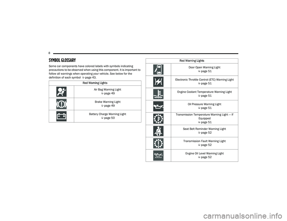
SYMBOL GLOSSARY
Some car components have colored labels with symbols indicating
precautions to be observed when using this component. It is important to
follow all warnings when operating your vehicle. See below for the
definition of each symbol Úpage 43.
Red Warning Lights
Air Bag Warning Light Úpage 49
Brake Warning Light Úpage 49
Battery Charge Warning Light Úpage 50
Red Warning Lights
Door Open Warning Light Úpage 51
Electronic Throttle Control (ETC) Warning Light Úpage 51
Engine Coolant Temperature Warning Light Úpage 51
Oil Pressure Warning Light Úpage 51
Transmission Temperature Warning Light — If Equipped
Ú page 51
Seat Belt Reminder Warning Light Úpage 52
Transmission Fault Warning Light Úpage 52
Engine Oil Level Warning Light Úpage 52
21_VM_OM_EN_USC_t.book Page 8
Page 19 of 280
GETTING TO KNOW YOUR VEHICLE17
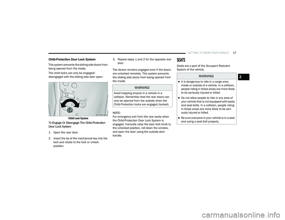
Child-Protection Door Lock System
This system prevents the sliding side doors from
being opened from the inside.
The child locks can only be engaged/
disengaged with the sliding side door open:
Child Lock System
To Engage Or Disengage The Child-Protection
Door Lock System
1. Open the rear door.
2. Insert the tip of the mechanical key into the lock and rotate to the lock or unlock
position. 3. Repeat steps 1 and 2 for the opposite rear
door.
The device remains engaged even if the doors
are unlocked remotely. This system prevents
the sliding side doors from being opened from
the inside.
NOTE:
For emergency exit from the rear seats when
the Child-Protection Door Lock System is
engaged, manually raise the door lock knob to
the unlocked position, roll down the window,
and open the door using the outside door
handle.
SEATS
Seats are a part of the Occupant Restraint
System of the vehicle.
WARNING!
Avoid trapping anyone in a vehicle in a
collision. Remember that the rear doors can
only be opened from the outside when the
Child-Protection locks are engaged (locked).
WARNING!
It is dangerous to ride in a cargo area,
inside or outside of a vehicle. In a collision,
people riding in these areas are more likely
to be seriously injured or killed.
Do not allow people to ride in any area of
your vehicle that is not equipped with seats
and seat belts. In a collision, people riding
in these areas are more likely to be seri -
ously injured or killed.
Be sure everyone in your vehicle is in a seat
and using a seat belt properly.
2
21_VM_OM_EN_USC_t.book Page 17
Page 20 of 280
18GETTING TO KNOW YOUR VEHICLE
Manual Adjustment (Front Seats)
The front driver and passenger seats can be
adjusted forward and rearward, and (if
equipped), may be reclined and the height and
lumbar can be adjusted.
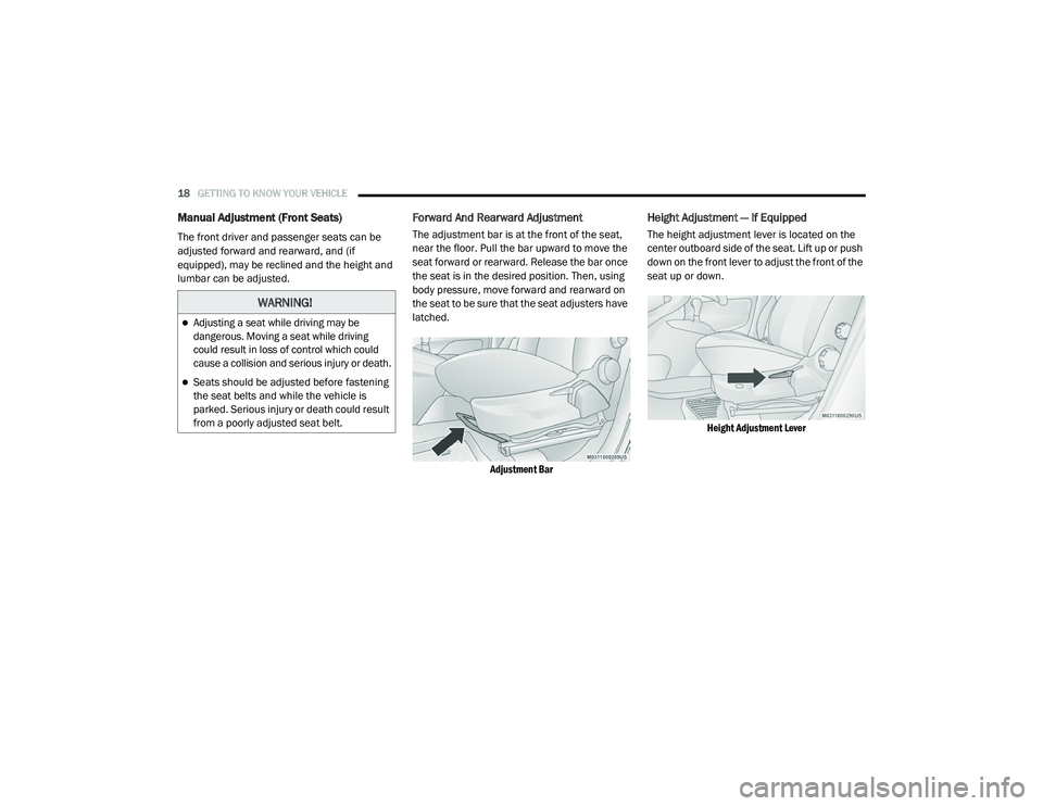
Forward And Rearward Adjustment
The adjustment bar is at the front of the seat,
near the floor. Pull the bar upward to move the
seat forward or rearward. Release the bar once
the seat is in the desired position. Then, using
body pressure, move forward and rearward on
the seat to be sure that the seat adjusters have
latched.
Adjustment Bar
Height Adjustment — If Equipped
The height adjustment lever is located on the
center outboard side of the seat. Lift up or push
down on the front lever to adjust the front of the
seat up or down.
Height Adjustment Lever
WARNING!
Adjusting a seat while driving may be
dangerous. Moving a seat while driving
could result in loss of control which could
cause a collision and serious injury or death.
Seats should be adjusted before fastening
the seat belts and while the vehicle is
parked. Serious injury or death could result
from a poorly adjusted seat belt.
21_VM_OM_EN_USC_t.book Page 18
Page 21 of 280
GETTING TO KNOW YOUR VEHICLE19
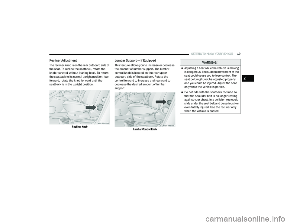
Recliner Adjustment
The recliner knob is on the rear outboard side of
the seat. To recline the seatback, rotate the
knob rearward without leaning back. To return
the seatback to its normal upright position, lean
forward, rotate the knob forward until the
seatback is in the upright position.
Recliner Knob
Lumbar Support — If Equipped
This feature allows you to increase or decrease
the amount of lumbar support. The lumbar
control knob is located on the rear upper
outboard side of the seatback. Rotate the
control forward to increase and rearward to
decrease the desired amount of lumbar
support.
Lumbar Control Knob
WARNING!
Adjusting a seat while the vehicle is moving
is dangerous. The sudden movement of the
seat could cause you to lose control. The
seat belt might not be adjusted properly
and you could be injured. Adjust the seat
only while the vehicle is parked.
Do not ride with the seatback reclined so
that the shoulder belt is no longer resting
against your chest. In a collision you could
slide under the seat belt and be seriously or
even fatally injured. Use the recliner only
when the vehicle is parked.
2
21_VM_OM_EN_USC_t.book Page 19
Page 40 of 280
38GETTING TO KNOW YOUR VEHICLE
(Continued)
CARGO AREA FEATURES
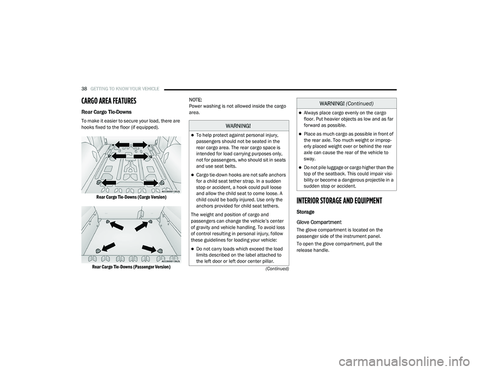
Rear Cargo Tie-Downs
To make it easier to secure your load, there are
hooks fixed to the floor (if equipped).
Rear Cargo Tie-Downs (Cargo Version)
Rear Cargo Tie-Downs (Passenger Version)
NOTE:
Power washing is not allowed inside the cargo
area.
INTERIOR STORAGE AND EQUIPMENT
Storage
Glove Compartment
The glove compartment is located on the
passenger side of the instrument panel.
To open the glove compartment, pull the
release handle.
WARNING!
To help protect against personal injury,
passengers should not be seated in the
rear cargo area. The rear cargo space is
intended for load carrying purposes only,
not for passengers, who should sit in seats
and use seat belts.
Cargo tie-down hooks are not safe anchors
for a child seat tether strap. In a sudden
stop or accident, a hook could pull loose
and allow the child seat to come loose. A
child could be badly injured. Use only the
anchors provided for child seat tethers.
The weight and position of cargo and
passengers can change the vehicle’s center
of gravity and vehicle handling. To avoid loss
of control resulting in personal injury, follow
these guidelines for loading your vehicle:
Do not carry loads which exceed the load
limits described on the label attached to
the left door or left door center pillar.
Always place cargo evenly on the cargo
floor. Put heavier objects as low and as far
forward as possible.
Place as much cargo as possible in front of
the rear axle. Too much weight or improp -
erly placed weight over or behind the rear
axle can cause the rear of the vehicle to
sway.
Do not pile luggage or cargo higher than the
top of the seatback. This could impair visi-
bility or become a dangerous projectile in a
sudden stop or accident.
WARNING! (Continued)
21_VM_OM_EN_USC_t.book Page 38
Page 49 of 280
GETTING TO KNOW YOUR INSTRUMENT PANEL47
Push the MENU button briefly to return to the
menu screen or hold the MENU button down to
return to the standard screen without storing.
To cancel the setting:
1. Briefly push the
MENU
button, “ON” will
flash in the display.
2. Push the down arrow button, “OFF” will
flash in the display.
3. Push the MENU button briefly to return to
the menu screen or hold the MENU button
down to return to the standard screen
without storing.
Trip B Data
This function can be used to activate (On) or
deactivate (Off) the Trip B display (Partial Trip)
Ú page 47.
To switch the function On/Off:
1. Push the
MENU
button briefly. The display
will flash On or Off according to the
previous setting.
2. Push and release the up or down
arrow button to select. Push the
MENU button briefly to return to the
menu screen or hold the MENU button down to
return to the standard screen without storing.
Buzzer Volume
With this function, the volume of the acoustic
signal which accompanies the display of
failure/warning can be adjusted according to
seven levels.
To set the desired volume:
1. Push the
MENU
button, the previously set
volume level will flash on the display.
2. Push and release the up or down
arrow button to adjust.
3. Push the MENU button to return to the
menu screen or hold the MENU button
down to return to the standard screen
without storing.
Seat Belt Buzzer
Only shows in the instrument cluster display if
the seat belt reminder was previously
deactivated by an authorized dealer. NOTE:
This is a one-time occurrence to enable the
acoustic signal.
Exit Menu
This is the last function that closes the cycle of
settings listed in the menu screen.
1. Pushing the
MENU
button briefly will return
the display to the standard screen without
storing.
2. Push the down arrow button to return to
the first menu item on the display.
TRIP COMPUTER
The Trip Computer is located in the instrument
cluster. It features a driver interactive display
(displays information such as trip information,
range, fuel consumption, average speed, and
travel time).
NOTE:
The Uconnect System also has a Trip Computer
display and menus to customize the informa -
tion displayed in the cluster Ú page 87.
3
21_VM_OM_EN_USC_t.book Page 47
Page 54 of 280

52GETTING TO KNOW YOUR INSTRUMENT PANEL
Seat Belt Reminder Warning Light
When the ignition is first placed in the
ON/RUN or MAR/ON/RUN position, if
the driver’s seat belt is unbuckled, a
chime will sound and the light will turn
on. When driving, if the driver or front passenger
seat belt remains unbuckled, the Seat Belt
Reminder Light will flash or remain on
continuously and a chime will sound
Ú page 153.
Transmission Fault Warning Light
This light will illuminate (together with
a message in the instrument cluster
display and a buzzer) to indicate a
transmission fault. Contact an
authorized dealer if the message remains after
restarting the engine.
Engine Oil Level Warning Light
This warning light appears on the
panel when the engine oil level falls
below the minimum recommended
value. Restore the correct engine oil
level or contact your authorized dealer for
service.
Yellow Warning Lights
Anti-Lock Brake System (ABS) Warning Light
This light monitors the ABS. The light
will turn on when the ignition is placed
in the ON/RUN or MAR/ON/RUN
position and may stay on for as long
as four seconds.
If the ABS light remains on or turns on while
driving, then the Anti-Lock portion of the brake
system is not functioning and service is
required. However, the conventional brake system will continue to operate normally if the
brake warning light is not on.
If the ABS light is on, the brake system should
be serviced as soon as possible to restore the
benefits of Anti-Lock Brakes. If the ABS light
does not turn on when the ignition is placed in
the ON/RUN or MAR/ON/RUN position, have
the light inspected by an authorized dealer.
Low Fuel Warning Light
When the fuel level reaches
approximately 2–3 gal (9–11 L) this
light will turn on, and remain on until
fuel is added.
Generic Warning Light
The Generic Warning Light will
illuminate if any of the following
conditions occur: Engine Oil Pressure
Sensor Failure, External Light Failure,
Parking Sensor Failure, Fuel Cut-Off Fail/
Intervention, Generic Failure on Trailer, or Air
Bag telltale recovery.
The telltale will blink in case of an Air Bag
Warning Light Failure. Contact an authorized
dealer immediately for service.
WARNING!
If you continue operating the vehicle when
the Transmission Temperature Warning Light
is illuminated you could cause the fluid to boil
over, come in contact with hot engine or
exhaust components and cause a fire.
CAUTION!
Continuous driving with the Transmission
Temperature Warning Light illuminated will
eventually cause severe transmission
damage or transmission failure.
21_VM_OM_EN_USC_t.book Page 52