2021 RAM PROMASTER CITY ECU
[x] Cancel search: ECUPage 25 of 280
GETTING TO KNOW YOUR VEHICLE23
Rear Removal — If Equipped
Outboard Head Restraints
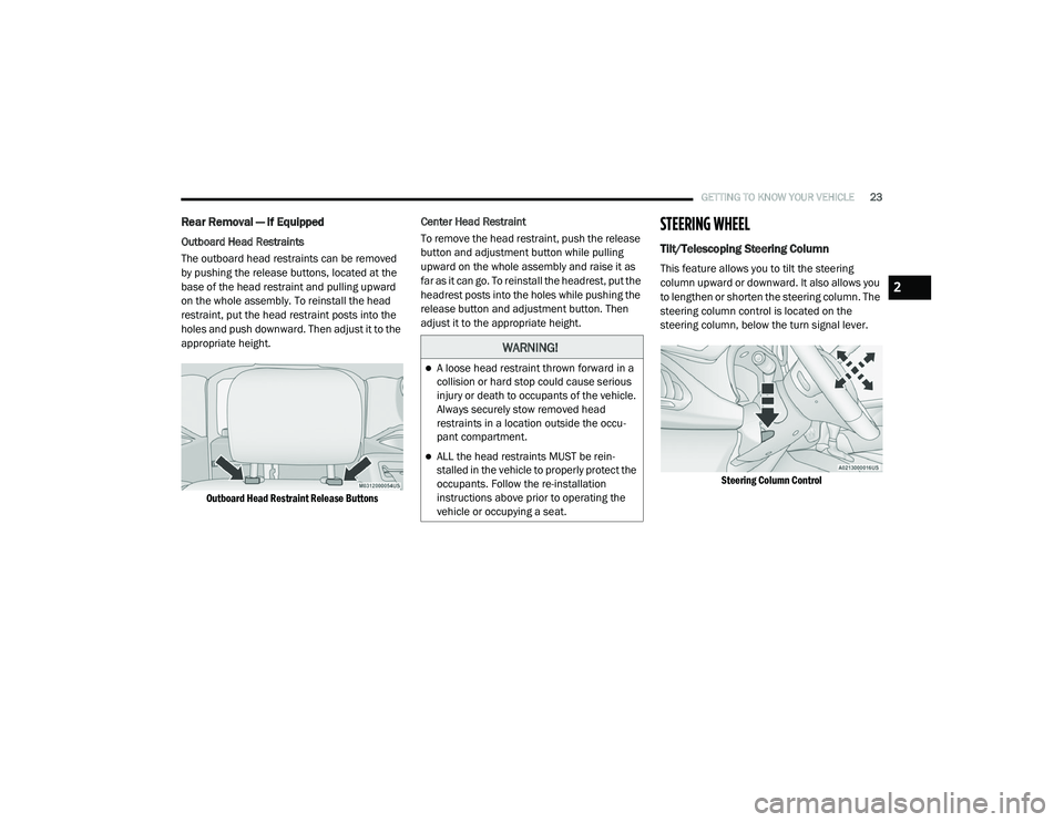
The outboard head restraints can be removed
by pushing the release buttons, located at the
base of the head restraint and pulling upward
on the whole assembly. To reinstall the head
restraint, put the head restraint posts into the
holes and push downward. Then adjust it to the
appropriate height.
Outboard Head Restraint Release Buttons
Center Head Restraint
To remove the head restraint, push the release
button and adjustment button while pulling
upward on the whole assembly and raise it as
far as it can go. To reinstall the headrest, put the
headrest posts into the holes while pushing the
release button and adjustment button. Then
adjust it to the appropriate height.
STEERING WHEEL
Tilt/Telescoping Steering Column
This feature allows you to tilt the steering
column upward or downward. It also allows you
to lengthen or shorten the steering column. The
steering column control is located on the
steering column, below the turn signal lever.
Steering Column Control
WARNING!
A loose head restraint thrown forward in a
collision or hard stop could cause serious
injury or death to occupants of the vehicle.
Always securely stow removed head
restraints in a location outside the occu -
pant compartment.
ALL the head restraints MUST be rein -
stalled in the vehicle to properly protect the
occupants. Follow the re-installation
instructions above prior to operating the
vehicle or occupying a seat.
2
21_VM_OM_EN_USC_t.book Page 23
Page 39 of 280
GETTING TO KNOW YOUR VEHICLE37
HOOD
Opening
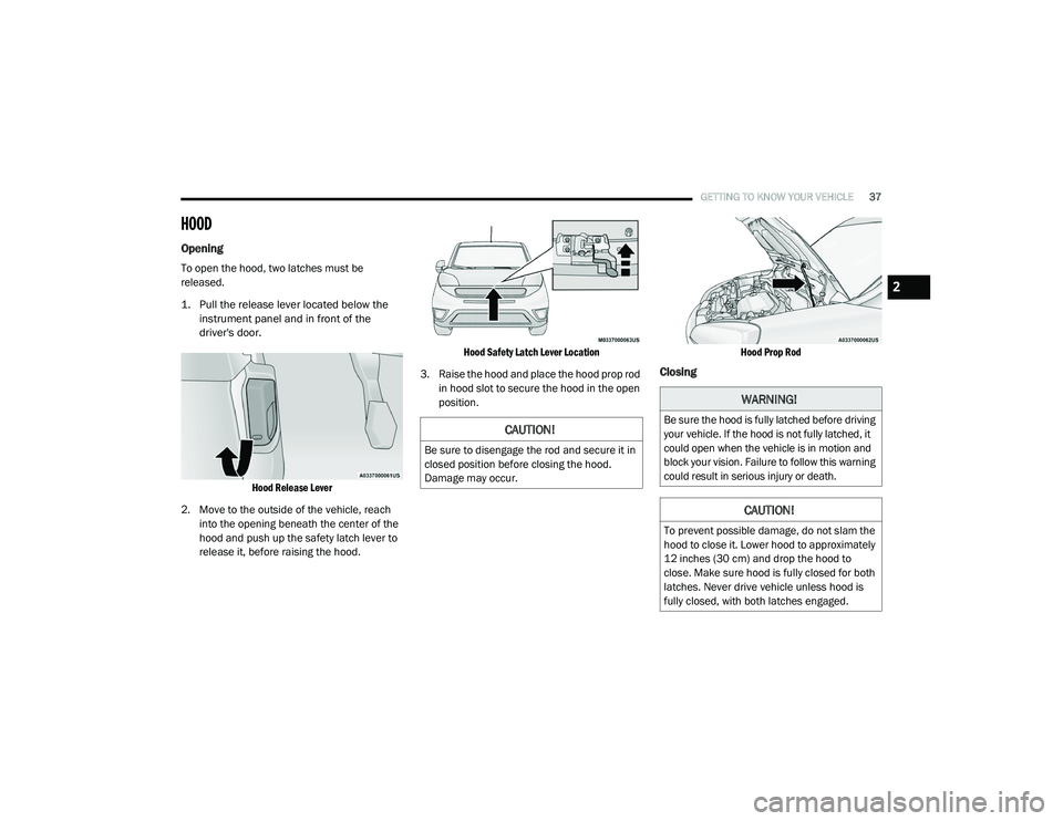
To open the hood, two latches must be
released.
1. Pull the release lever located below the
instrument panel and in front of the
driver's door.
Hood Release Lever
2. Move to the outside of the vehicle, reach into the opening beneath the center of the
hood and push up the safety latch lever to
release it, before raising the hood.
Hood Safety Latch Lever Location
3. Raise the hood and place the hood prop rod in hood slot to secure the hood in the open
position.
Hood Prop Rod
Closing
CAUTION!
Be sure to disengage the rod and secure it in
closed position before closing the hood.
Damage may occur.
WARNING!
Be sure the hood is fully latched before driving
your vehicle. If the hood is not fully latched, it
could open when the vehicle is in motion and
block your vision. Failure to follow this warning
could result in serious injury or death.
CAUTION!
To prevent possible damage, do not slam the
hood to close it. Lower hood to approximately
12 inches (30 cm) and drop the hood to
close. Make sure hood is fully closed for both
latches. Never drive vehicle unless hood is
fully closed, with both latches engaged.
2
21_VM_OM_EN_USC_t.book Page 37
Page 40 of 280
38GETTING TO KNOW YOUR VEHICLE
(Continued)
CARGO AREA FEATURES
Rear Cargo Tie-Downs
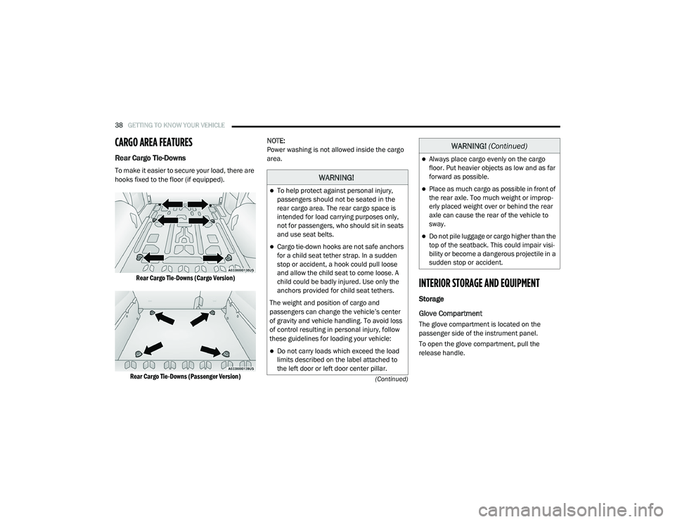
To make it easier to secure your load, there are
hooks fixed to the floor (if equipped).
Rear Cargo Tie-Downs (Cargo Version)
Rear Cargo Tie-Downs (Passenger Version)
NOTE:
Power washing is not allowed inside the cargo
area.
INTERIOR STORAGE AND EQUIPMENT
Storage
Glove Compartment
The glove compartment is located on the
passenger side of the instrument panel.
To open the glove compartment, pull the
release handle.
WARNING!
To help protect against personal injury,
passengers should not be seated in the
rear cargo area. The rear cargo space is
intended for load carrying purposes only,
not for passengers, who should sit in seats
and use seat belts.
Cargo tie-down hooks are not safe anchors
for a child seat tether strap. In a sudden
stop or accident, a hook could pull loose
and allow the child seat to come loose. A
child could be badly injured. Use only the
anchors provided for child seat tethers.
The weight and position of cargo and
passengers can change the vehicle’s center
of gravity and vehicle handling. To avoid loss
of control resulting in personal injury, follow
these guidelines for loading your vehicle:
Do not carry loads which exceed the load
limits described on the label attached to
the left door or left door center pillar.
Always place cargo evenly on the cargo
floor. Put heavier objects as low and as far
forward as possible.
Place as much cargo as possible in front of
the rear axle. Too much weight or improp -
erly placed weight over or behind the rear
axle can cause the rear of the vehicle to
sway.
Do not pile luggage or cargo higher than the
top of the seatback. This could impair visi-
bility or become a dangerous projectile in a
sudden stop or accident.
WARNING! (Continued)
21_VM_OM_EN_USC_t.book Page 38
Page 44 of 280
42GETTING TO KNOW YOUR VEHICLE
(Continued)
To move the crossbars, loosen the
attachments, located at the upper edge of each
crossbar, approximately eight turns using the
anti-theft wrench provided with the Mopar
crossbars. Then, move the crossbar to the
desired position, keeping the crossbars parallel
to the rack frame. Once the crossbar is in the
desired position, re-tighten it with the wrench to
lock the crossbar into position.
NOTE:
To help control wind noise when the cross-
bars are not in use, place the front and rear
crossbars approximately 24 inches (61 cm)
apart. Optimal noise reduction can then be
achieved by adjusting the front crossbar
forward or aft using increments of 1 inch
(2.5 cm).
If the crossbar (or any metallic object) is
placed over the satellite radio antenna (if
equipped), you may experience interruption
of satellite radio reception. For improved
satellite radio reception, avoid placing the
rear crossbar over the satellite radio
antenna.
WARNING!
Cargo must be securely tied down before
driving your vehicle. Improperly secured loads
can fly off the vehicle, particularly at high
speeds, resulting in personal injury or
property damage. Follow the roof rack
cautions when carrying cargo on your roof
rack.
CAUTION!
To prevent damage to the roof of your
vehicle, DO NOT carry any loads on the roof
rack without the crossbars deployed. The
load should be secured and placed on top
of the crossbars, not directly on the roof. If
it is necessary to place the load on the roof,
place a blanket or other protective layer
between the load and the roof surface.
To avoid damage to the roof rack and
vehicle, do not exceed the maximum roof
rack load capacity of 150 lb (68 kg). Always
distribute heavy loads as evenly as possible
and secure the load appropriately.
Loads should always be secured to cross -
bars first, with tie down loops used as addi -
tional securing points if needed. Tie loops
are intended as supplementary tie down
points only. Do not use ratcheting mecha -
nisms with the tie loops. Check the straps
and thumb wheels frequently to be sure
that the load remains securely attached.
Long loads that extend over the windshield,
such as wood panels or surfboards, or
loads with large frontal area should be
secured to both the front and rear of the
vehicle.
Travel at reduced speeds and turn corners
carefully when carrying large or heavy loads
on the roof rack. Wind forces, due to
natural causes or nearby truck traffic, can
add sudden upward lift to a load. This is
especially true on large flat loads and may
result in damage to the cargo or your
vehicle.
CAUTION! (Continued)
21_VM_OM_EN_USC_t.book Page 42
Page 56 of 280

54GETTING TO KNOW YOUR INSTRUMENT PANEL
Vehicle Security Warning Light
This warning light will illuminate when
the vehicle security system has
detected an attempt to break into the
vehicle.
Engine Check/Malfunction Indicator Warning
Light (MIL)
The Engine Check/Malfunction
Indicator Light (MIL) is a part of an
Onboard Diagnostic System called
OBD II that monitors engine and
automatic transmission control systems. This
warning light will illuminate when the ignition is in
the ON/RUN position before engine start. After
placing the ignition to the ON/RUN position, if
there is a problem with the Sentry Key System,
the Vehicle Security Light will turn on. This
condition will result in the engine being shut off
after two seconds. If the bulb does not come on
when turning the ignition switch from OFF to ON/
RUN, have the condition checked promptly.
NOTE:
This warning light will illuminate when the
vehicle security system has detected an
attempt to break into the vehicle.
Certain conditions, such as a loose or missing
gas cap, poor quality fuel, etc., may illuminate the
light after engine start. The vehicle should be
serviced if the light stays on through several
typical driving styles. In most situations, the
vehicle will drive normally and will not require
towing. When the engine is running, the MIL may flash
to alert serious conditions that could lead to
immediate loss of power or severe catalytic
converter damage. The vehicle should be
serviced by an authorized dealer as soon as
possible if this occurs.
CAUTION!
The TPMS has been optimized for the original
equipment tires and wheels. TPMS pressures
and warning have been established for the
tire size equipped on your vehicle.
Undesirable system operation or sensor
damage may result when using replacement
equipment that is not of the same size, type,
and/or style. Aftermarket wheels can cause
sensor damage. Using aftermarket tire
sealants may cause the Tire Pressure
Monitoring System (TPMS) sensor to become
inoperable. After using an aftermarket tire
sealant it is recommended that you take your
vehicle to an authorized dealer to have your
sensor function checked.
WARNING!
A malfunctioning catalytic converter, as refer
-
enced above, can reach higher temperatures
than in normal operating conditions. This can
cause a fire if you drive slowly or park over
flammable substances such as dry plants,
wood, cardboard, etc. This could result in
death or serious injury to the driver, occu -
pants or others.
CAUTION!
Prolonged driving with the Malfunction
Indicator Light (MIL) on could cause damage
to the vehicle control system. It also could
affect fuel economy and driveability. If the
MIL is flashing, severe catalytic converter
damage and power loss will soon occur.
Immediate service is required.
21_VM_OM_EN_USC_t.book Page 54
Page 58 of 280

56GETTING TO KNOW YOUR INSTRUMENT PANEL
Blue Indicator Lights
High Beam Indicator Light
This indicator light will illuminate to
indicate that the high beam
headlights are on. With the low beams
activated, push the multifunction
lever forward (toward the front of the vehicle) to
turn on the high beams. Pull the multifunction
lever rearward (toward the rear of the vehicle) to
turn off the high beams. If the high beams are
off, pull the lever toward you for a temporary
high beam on, “flash to pass” scenario.
ONBOARD DIAGNOSTIC SYSTEM — OBD II
Your vehicle is equipped with a sophisticated
Onboard Diagnostic system called OBD II. This
system monitors the performance of the
emissions, engine, and transmission control
systems. When these systems are operating
properly, your vehicle will provide excellent
performance and fuel economy, as well as
engine emissions well within current
government regulations.
If any of these systems require service, the OBD
II system will turn on the Malfunction Indicator
Light (MIL). It will also store diagnostic codes
and other information to assist your service technician in making repairs. Although your
vehicle will usually be drivable and not need
towing, see an authorized dealer for service as
soon as possible.
Onboard Diagnostic System (OBD II)
Cybersecurity
Your vehicle is required to have an Onboard
Diagnostic system (OBD II) and a connection
port to allow access to information related to
the performance of your emissions controls.
Authorized service technicians may need to
access this information to assist with the
diagnosis and service of your vehicle and
emissions system Ú
page 86.
CAUTION!
Prolonged driving with the MIL on could
cause further damage to the emission
control system. It could also affect fuel
economy and driveability. The vehicle must
be serviced before any emissions tests can
be performed.
If the MIL is flashing while the vehicle is
running, severe catalytic converter damage
and power loss will soon occur. Immediate
service is required.
WARNING!
ONLY an authorized service technician
should connect equipment to the OBD II
connection port in order to read the VIN,
diagnose, or service your vehicle.
If unauthorized equipment is connected to
the OBD II connection port, such as a
driver-behavior tracking device, it may:
Be possible that vehicle systems,
including safety related systems, could
be impaired or a loss of vehicle control
could occur that may result in an acci -
dent involving serious injury or death.
Access, or allow others to access, infor -
mation stored in your vehicle systems,
including personal information.
21_VM_OM_EN_USC_t.book Page 56
Page 62 of 280

60STARTING AND OPERATING
1. Locate the engine block heater cord
(behind the driver’s side headlamp).
2. Undo the hook-and-loop strap that secures the heater cord in place.
3. Pull the cord to the front of the vehicle and plug it into a grounded, three-wire extension
cord.
4. After the vehicle is running, reattach the cord to the hook-and-loop strap and
properly stow away behind the driver’s side
headlamp.
NOTE:
The engine block heater cord is a factory
installed option. If your vehicle is not
equipped, heater cords are available from an
authorized Mopar dealer.
The engine block heater will require 110 Volts
AC and 6.5 Amps to activate the heater
element.
The engine block heater must be plugged in
at least one hour to have an adequate
warming effect on the engine.
ENGINE BREAK-IN RECOMMENDATIONS
A long break-in period is not required for the
engine and drivetrain (transmission and axle) in
your vehicle.
Drive moderately during the first 300 miles
(500 km). After the initial 60 miles (100 km),
speeds up to 50 or 55 mph (80 or 90 km/h) are
desirable.
While cruising, brief full-throttle acceleration
within the limits of local traffic laws contributes
to a good break-in. Wide-open throttle
acceleration in low gear can be detrimental and
should be avoided.
The engine oil installed in the engine at the
factory is a high-quality energy conserving type
lubricant. Oil changes should be consistent with
anticipated climate conditions under which
vehicle operations will occur. For the
recommended viscosity and quality grades
Ú page 259. NOTE:
A new engine may consume some oil during its
first few thousand miles (kilometers) of opera
-
tion. This should be considered a normal part of
the break-in and not interpreted as a concern.
Please check your oil level with the engine oil
indicator often during the break in period. Add
oil as required.
PARKING BRAKE
Before leaving the vehicle, make sure that the
parking brake is fully applied. Also, be certain to
leave an automatic transmission in PARK.
The parking brake lever is located in the center
console. To apply the parking brake, pull the
lever up as firmly as possible. To release the
parking brake, pull the lever up slightly, push
the center button, then lower the lever
completely.
WARNING!
Remember to disconnect the engine block
heater cord before driving. Damage to the
110-115 Volt electrical cord could cause
electrocution.
CAUTION!
Never use Non-Detergent Oil or Straight
Mineral Oil in the engine or damage may
result.
21_VM_OM_EN_USC_t.book Page 60
Page 64 of 280
62STARTING AND OPERATING
(Continued)
AUTOMATIC TRANSMISSION
You must press and hold the brake pedal while
shifting out of PARK.
Key Ignition Park Interlock
This vehicle is equipped with a Key Ignition Park
Interlock which requires the transmission to be
in PARK before the ignition can be turned to the
full STOP (OFF/LOCK) (key removal) position.
The key can only be removed from the ignition
when the ignition is in the STOP (OFF/LOCK)
position, and once removed, the transmission is
locked in PARK.
WARNING!
It is dangerous to shift out of PARK or
NEUTRAL if the engine speed is higher than
idle speed. If your foot is not firmly pressing
the brake pedal, the vehicle could accel -
erate quickly forward or in reverse. You
could lose control of the vehicle and hit
someone or something. Only shift into gear
when the engine is idling normally and your
foot is firmly pressing the brake pedal.
Unintended movement of a vehicle could
injure those in or near the vehicle. As with
all vehicles, you should never exit a vehicle
while the engine is running. Before exiting a
vehicle always come to a complete stop,
then apply the parking brake, shift the
transmission into PARK, turn the engine
OFF, and remove the ignition key. Once the
key is removed, the transmission is locked
in PARK, securing the vehicle against
unwanted movement.
When leaving the vehicle, always remove
the ignition key from the vehicle and lock
the vehicle.
Never leave children alone in a vehicle, or
with access to an unlocked vehicle.
Allowing children to be in a vehicle unat -
tended is dangerous for a number of
reasons. A child or others could be seriously
or fatally injured. Children should be
warned not to touch the parking brake,
brake pedal or the transmission gear
selector.
Do not leave the ignition key in or near the
vehicle (or in a location accessible to chil -
dren). A child could operate power
windows, other controls, or move the
vehicle.
WARNING! (Continued)CAUTION!
Shift into or out of PARK or REVERSE only
after the vehicle has come to a complete
stop.
Do not shift between PARK, REVERSE,
NEUTRAL, or DRIVE when the engine is
above idle speed.
Before shifting into any gear, make sure
your foot is firmly pressing the brake pedal.
21_VM_OM_EN_USC_t.book Page 62