Page 131 of 212
129
In the event of a breakdown
8
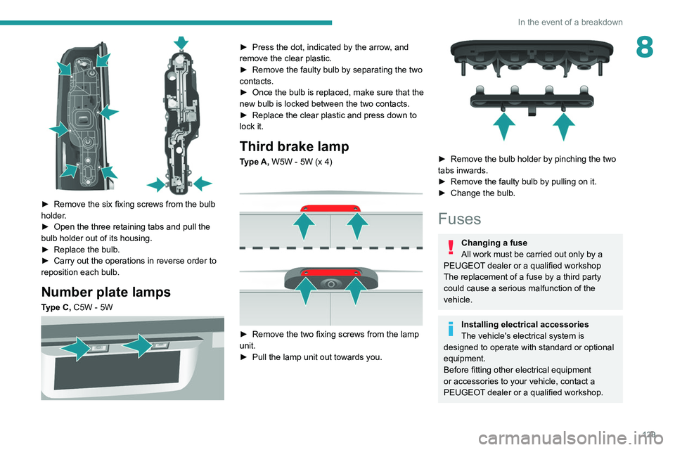
► Remove the six fixing screws from the bulb
holder .
►
Open the three retaining tabs and pull the
bulb holder out of its housing.
►
Replace the bulb.
►
Carry out the operations in reverse order to
reposition each bulb.
Number plate lamps
Type C, C5W - 5W
► Press the dot, indicated by the arrow , and
remove the clear plastic.
►
Remove the faulty bulb by separating the two
contacts.
►
Once the bulb is replaced, make sure that the
new bulb is locked between the two contacts.
►
Replace the clear plastic and press down to
lock it.
Third brake lamp
Type A, W5W - 5W (x 4)
► Remove the two fixing screws from the lamp
unit.
►
Pull the lamp unit out towards you.
► Remove the bulb holder by pinching the two
tabs inwards.
►
Remove the faulty bulb by pulling on it.
►
Change the bulb.
Fuses
Changing a fuse
All work must be carried out only by a
PEUGEOT dealer or a qualified workshop
The replacement of a fuse by a third party
could cause a serious malfunction of the
vehicle.
Installing electrical accessories
The vehicle's electrical system is
designed to operate with standard or optional
equipment.
Before fitting other electrical equipment
or accessories to your vehicle, contact a
PEUGEOT dealer or a qualified workshop.
Page 134 of 212
132
In the event of a breakdown
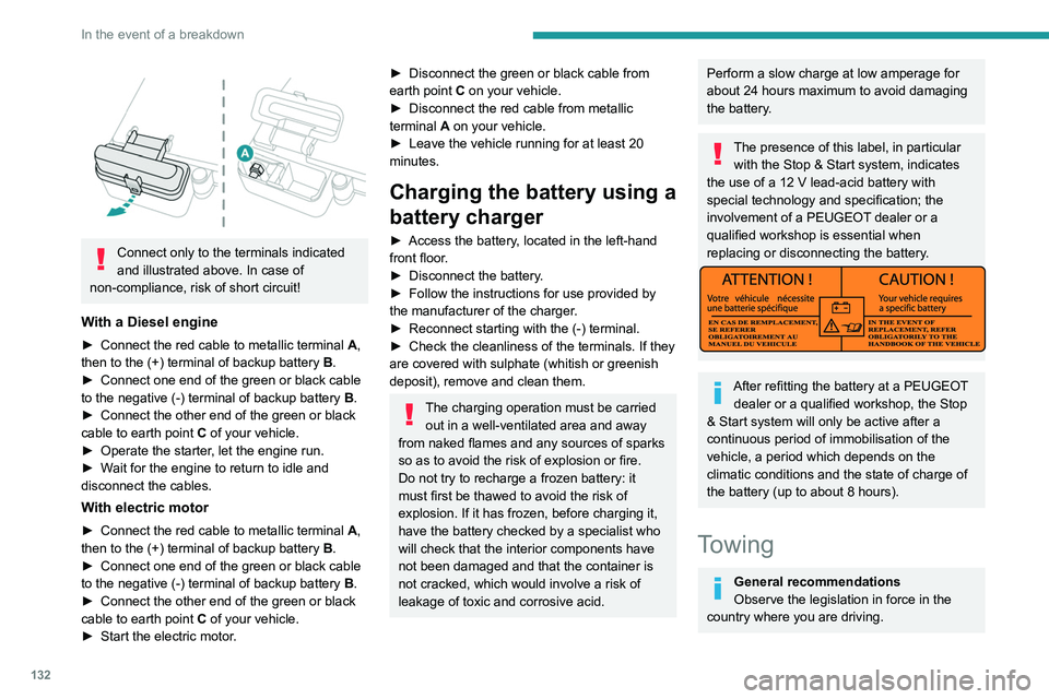
Connect only to the terminals indicated
and illustrated above. In case of
non-compliance, risk of short circuit!
With a Diesel engine
► Connect the red cable to metallic terminal A,
then to the (+) terminal of backup battery B.
►
Connect one end of the green or black cable
to the negative (-) terminal of backup battery B
.
►
Connect the other end of the green or black
cable to earth point C
of your vehicle.
►
Operate the starter
, let the engine run.
►
W
ait for the engine to return to idle and
disconnect the cables.
With electric motor
► Connect the red cable to metallic terminal A,
then to the (+) terminal of backup battery B.
►
Connect one end of the green or black cable
to the negative (-) terminal of backup battery B
.
►
Connect the other end of the green or black
cable to earth point C
of your vehicle.
►
Start the electric motor
.
► Disconnect the green or black cable from
earth point C on your vehicle.
►
Disconnect the red cable from metallic
terminal
A on your vehicle.
►
Leave the vehicle running for at least 20
minutes.
Charging the battery using a
battery charger
► Access the battery , located in the left-hand
front floor.
►
Disconnect the battery
.
►
Follow the instructions for use provided by
the manufacturer of the charger
.
►
Reconnect starting with the (-) terminal.
►
Check the cleanliness of the terminals. If they
are covered with sulphate (whitish or greenish
deposit), remove and clean them.
The charging operation must be carried out in a well-ventilated area and away
from naked flames and any sources of sparks
so as to avoid the risk of explosion or fire.
Do not try to recharge a frozen battery: it
must first be thawed to avoid the risk of
explosion. If it has frozen, before charging it,
have the battery checked by a specialist who
will check that the interior components have
not been damaged and that the container is
not cracked, which would involve a risk of
leakage of toxic and corrosive acid.
Perform a slow charge at low amperage for
about 24 hours maximum to avoid damaging
the battery.
The presence of this label, in particular with the Stop & Start system, indicates
the use of a 12 V lead-acid battery with
special technology and specification; the
involvement of a PEUGEOT dealer or a
qualified workshop is essential when
replacing or disconnecting the battery.
After refitting the battery at a PEUGEOT dealer or a qualified workshop, the Stop
& Start system will only be active after a
continuous period of immobilisation of the
vehicle, a period which depends on the
climatic conditions and the state of charge of
the battery (up to about 8 hours).
Towing
General recommendations
Observe the legislation in force in the
country where you are driving.
Page 135 of 212
133
In the event of a breakdown
8Ensure that the weight of the towing vehicle is
higher than that of the towed vehicle.
The driver must remain at the wheel of the
towed vehicle and must have a valid driving
licence.
When towing a vehicle with all four wheels on
the ground, always use an approved towing
arm; rope and straps are prohibited.
The towing vehicle must move off gently.
When the vehicle is towed with its engine
off, there is no longer braking and steering
assistance.A professional towing service must be
called if:
–
Broken down on a motorway or main road.
–
Not possible to put
the gearbox into neutral,
unlock the steering, or release the parking
brake.
–
Not possible to tow a vehicle with an
automatic gearbox, with the engine running.
–
T
owing with only two wheels on the ground.
–
Four-wheel drive vehicle.
–
No approved towbar available.
Before towing the vehicle, it is essential
to put the vehicle in free-wheeling mode.
Electric motor
An electric vehicle cannot under any
circumstances be used to tow another
vehicle.
However, it may be used, for example, to exit
a rut.
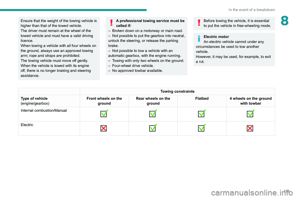
Towing constraints
Type of vehicle
(engine/gearbox) Front wheels on the
ground Rear wheels on the
ground Flatbed
4 wheels on the ground
with towbar
Internal combustion/Manual
Electric
Page 136 of 212
134
In the event of a breakdown
Towing your vehicle
The removable towing eye is located in the tool
box under the front passenger seat.
►
Unclip the cover using a flat tool.
► Screw the removable towing eye in fully .
► Attach the approved towbar to the removable
towing eye.
►
Place the gear lever in neutral.
Failure to adhere to this instruction may
lead to damage to braking system
components and the lack of braking
assistance on restarting the engine.
Towing another vehicle
The fixed towing eye is located under the
bumper, on the right-hand side.
►
Attach the approved towbar to the rigid eye.
Page 137 of 212
135
Technical data
9Engine technical data and
towed loads
Engines
The engine characteristics are given in the
vehicle's registration document, as well as in
sales brochures.
Only the values available at the time of
publication are presented in the tables.
Contact a PEUGEOT dealer or a qualified
workshop to obtain missing values.
The maximum power corresponds to the value type-approved on a test bed, under
conditions defined by European legislation
(Directive 1999/99/EC).
For more information, contact a PEUGEOT
dealer or a qualified workshop.
Weights and towed loads
The weights and towed loads relating to
the vehicle are indicated on the registration
document, as well as in sales brochures.
These values are also indicated on the
manufacturer's plate or label.
For more information, contact a PEUGEOT
dealer or a qualified workshop.
The GTW (Gross Train Weight) and towed load
values indicated are valid up to a maximum
altitude of 1,000 metres. The towed load value
must be reduced by 10% for each additional
1,000 metres of altitude.
The maximum authorised nose weight
corresponds to the weight permitted on the
towball.
When exterior temperatures are high, the
vehicle performance may be limited in
order to protect the engine. When the exterior
temperature is higher than 37°C, reduce the
towed weight.
Towing even with a lightly loaded vehicle can adversely affect its road holding.
Braking distances are increased when towing
a trailer.
When using a vehicle to tow, never exceed
a speed of 62 mph (100
km/h) (observe the
local legislation in force).
Page 140 of 212
138
Technical data
Weights and towed loads
These tables present the approved weight values (in kg) according to the dimensions and designations of the vehicle.
Minibus
DimensionsDesignationsGVWUnbraked trailerMaximum authorised
nose weight
L3 H2 4404,005XX
L4 H2 4424,250XX
For Combi versions, the maximum weight of the Braked trailer (within the GTW limit), on a 10% or 12% gradient, is: 2,500 kg.
5-6 seater Combi
DimensionsDesignationsGVWUnbraked trailerMaximum authorised
nose weight
L1 H1 3303,000750150*/100**
333 3,300750150*/100**
L2 H2 3333,300750150*/100**
435 3,500750150*/120**
7-8-9 seater Combi
DimensionsDesignationsGVWUnbraked trailerMaximum authorised
nose weight
L1 H1 3303,150750150*/100**
L2 H2 3333,300750150*/100**
* Euro 6.3 only.
** Except Euro 6.3.
Page 150 of 212
148
Special features
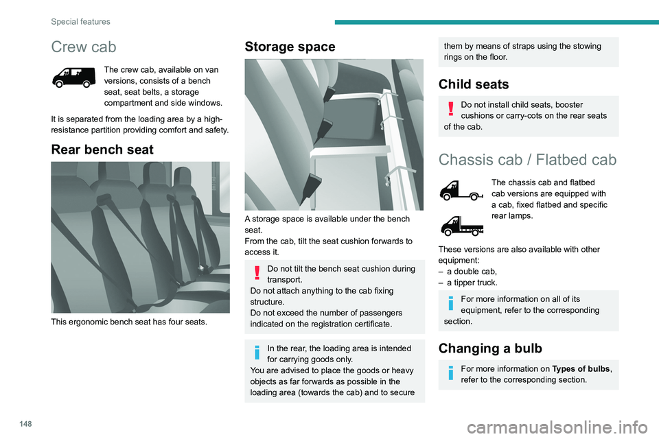
Crew cab
The crew cab, available on van
versions, consists of a bench
seat, seat belts, a storage
compartment and side windows.
It is separated from the loading area by a high-
resistance partition providing comfort and safety.
Rear bench seat
This ergonomic bench seat has four seats.
Storage space
A storage space is available under the bench
seat.
From the cab, tilt the seat cushion forwards to
access it.
Do not tilt the bench seat cushion during
transport.
Do not attach anything to the cab fixing
structure.
Do not exceed the number of passengers
indicated on the registration certificate.
In the rear, the loading area is intended
for carrying goods only.
You are advised to place the goods or heavy
objects as far forwards as possible in the
loading area (towards the cab) and to secure
them by means of straps using the stowing
rings on the floor.
Child seats
Do not install child seats, booster
cushions or carry-cots on the rear seats
of the cab.
Chassis cab / Flatbed cab
The chassis cab and flatbed
cab versions are equipped with
a cab, fixed flatbed and specific
rear lamps.
These versions are also available with other
equipment:
–
a double cab,
–
a tipper truck.
For more information on all of its
equipment, refer to the corresponding
section.
Changing a bulb
For more information on Types of bulbs,
refer to the corresponding section.
Page 151 of 212
149
Special features
10Rear lamps
1. Direction indicatorsType B, PY21W - 21W
2. Brake lamps Type B, P21W - 21W
3. Sidelamps Type A, W5W - 5W
4. Reversing lamps Type A, W16W - 16W
5. Foglamps Type A, W16W - 16W
►
Locate the faulty bulb.
► Remove the four fixing screws from the lens
unit.
►
Pull the lens unit towards you.
►
Change the bulb.
Carry out the operations in reverse order to
reposition each bulb.