2021 PEUGEOT BOXER tow
[x] Cancel search: towPage 106 of 212

104
Practical information
Installation tips
► To fit the snow chains during a journey, stop
the vehicle on a flat surface at the side of the
road.
►
Apply the parking brake and position any
wheel chocks under the wheels to prevent
movement of the vehicle.
►
Fit the snow chains following the instructions
provided by the manufacturer
.
►
Move off gently and drive for a few moments,
without exceeding 31
mph (50 km/h).
►
Stop the vehicle and check that the snow
chains are correctly tightened.
It is strongly recommended that you
practise fitting the snow chains on a level
and dry surface before setting off.
Avoid driving with snow chains on roads that have been cleared of snow to avoid
damaging the vehicle's tyres and the road
surface. If the vehicle is fitted with alloy
wheels, check that no part of the chain or its
fixings is in contact with the wheel rim.
Towing a trailer
The type-approved towable weights are entered
in your vehicle's registration certificate, as well
as on the manufacturer's plate.
For more information on the Technical
characteristics of the vehicle and
particularly on weights and towable loads,
refer to the corresponding section.
You will then have information on your vehicle's
ability to tow a trailer, a caravan, a boat, etc.
These values are also given in the sales
brochures.
We recommend using genuine
PEUGEOT towbars and their harnesses
that have been tested and approved from the
design stage of your vehicle, and having a
PEUGEOT dealer fit the towbar.
These genuine towbars are compatible with
the operation of the rear parking sensors and
the reversing camera, if your vehicle is so
equipped.
If the towbar is not fitted by a PEUGEOT
dealer, it must still be fitted in accordance with
the vehicle manufacturer's instructions.
Electric motor
An electric vehicle cannot under any
circumstances be fitted with a towing device.
It is therefore not possible to tow a trailer or
caravan.
Towbar with quickly detachable towball
Presentation
This genuine towball can be easily and quickly
fitted or removed. These operations do not
require any tools.
Page 107 of 212
105
Practical information
7
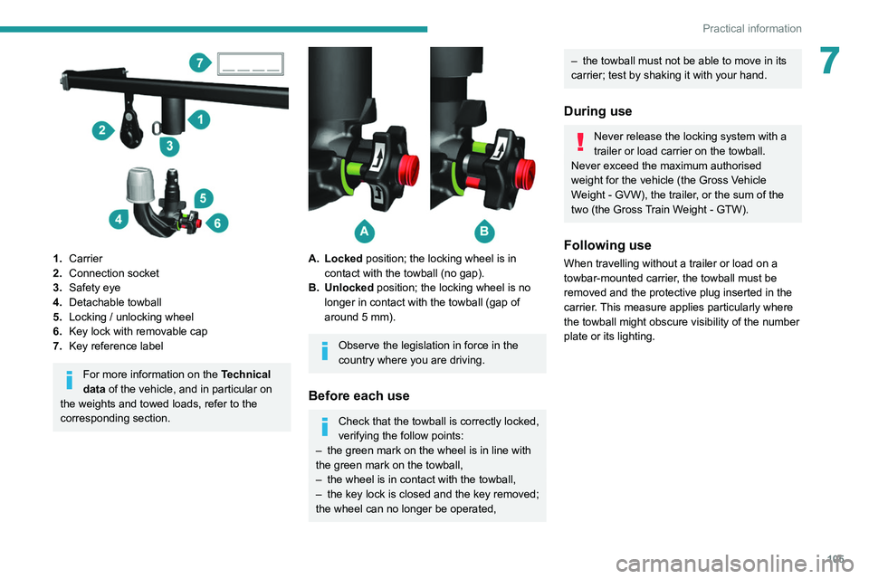
1.Carrier
2. Connection socket
3. Safety eye
4. Detachable towball
5. Locking / unlocking wheel
6. Key lock with removable cap
7. Key reference label
For more information on the Technical
data of the vehicle, and in particular on
the weights and towed loads, refer to the
corresponding section.
A. Locked position; the locking wheel is in contact with the towball (no gap).
B. Unlocked position; the locking wheel is no longer in contact with the towball (gap of
around 5 mm).
Observe the legislation in force in the
country where you are driving.
Before each use
Check that the towball is correctly locked,
verifying the follow points:
–
the green mark on the wheel is in line with
the green mark on the towball,
–
the wheel is in contact with the towball,
–
the key lock is closed and the key removed;
the wheel can no longer be operated,
– the towball must not be able to move in its
carrier; test by shaking it with your hand.
During use
Never release the locking system with a
trailer or load carrier on the towball.
Never exceed the maximum authorised
weight for the vehicle (the Gross Vehicle
Weight - GVW), the trailer, or the sum of the
two (the Gross Train Weight - GTW).
Following use
When travelling without a trailer or load on a
towbar-mounted carrier, the towball must be
removed and the protective plug inserted in the
carrier. This measure applies particularly where
the towball might obscure visibility of the number
plate or its lighting.
Page 108 of 212
106
Practical information
Fitting the towball
► Below the rear bumper, remove the protective
plug from the carrier.
►
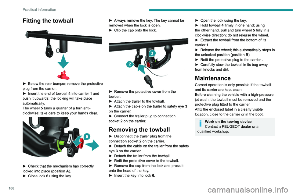
Insert the end of towball
4 into carrier 1 and
push it upwards; the locking will take place
automatically.
The wheel 5 turns a quarter of a turn anti-
clockwise; take care to keep your hands clear.
► Check that the mechanism has correctly
locked into place (position A ).
►
Close lock 6
using the key. ►
Always remove the key
. The key cannot be
removed when the lock is open.
►
Clip the cap onto the lock.
► Remove the protective cover from the
towball.
►
Attach the trailer to the towball.
►
Attach the cable on the trailer to safety eye
3
on the carrier.
►
Connect the trailer plug to connection
socket
2 on the carrier.
Removing the towball
► Disconnect the trailer plug from the
connection socket 2 on the carrier.
►
Detach the cable on the trailer from the safety
eye
3 on the carrier.
►
Detach the trailer from the towball.
►
Refit the protective cover to the towball.
►
Remove the cap from the lock and press it
onto the head of the key
.
►
Insert the key into lock
6.
► Open the lock using the key .
► Hold towball 4
firmly in one hand; using
the other hand, pull and turn wheel 5 fully in a
clockwise direction; do not release the wheel.
►
Extract the towball from the bottom of its
carrier
1.
►
Release the wheel; this automatically stops in
the unlocked position (position
B
).
►
Refit the protective plug to the carrier .
►
Carefully stow the towball in its bag away
from knocks and dirt.
Maintenance
Correct operation is only possible if the towball
and its carrier are kept clean.
Before cleaning the vehicle with a high-pressure
jet wash, the towball must be removed and the
protective plug fitted to the carrier.
Affix the enclosed label in a clearly visible
location, close to the carrier or in the boot.
Work on the towing device
Contact a PEUGEOT dealer or a
qualified workshop.
Page 109 of 212
107
Practical information
7Roof-mounted carrying
systems
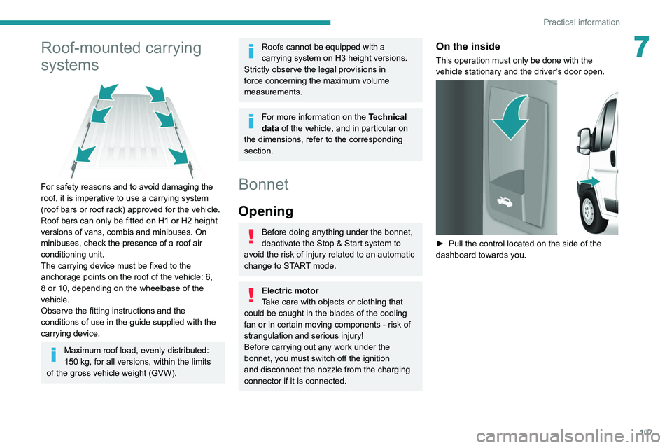
For safety reasons and to avoid damaging the
roof, it is imperative to use a carrying system
(roof bars or roof rack) approved for the vehicle.
Roof bars can only be fitted on H1 or H2 height
versions of vans, combis and minibuses. On
minibuses, check the presence of a roof air
conditioning unit.
The carrying device must be fixed to the
anchorage points on the roof of the vehicle: 6,
8 or 10, depending on the wheelbase of the
vehicle.
Observe the fitting instructions and the
conditions of use in the guide supplied with the
carrying device.
Maximum roof load, evenly distributed:
150 kg, for all versions, within the limits
of the gross vehicle weight (GVW).
Roofs cannot be equipped with a
carrying system on H3 height versions.
Strictly observe the legal provisions in
force concerning the maximum volume
measurements.
For more information on the Technical
data of the vehicle, and in particular on
the dimensions, refer to the corresponding
section.
Bonnet
Opening
Before doing anything under the bonnet,
deactivate the Stop & Start system to
avoid the risk of injury related to an automatic
change to START mode.
Electric motor
Take care with objects or clothing that
could be caught in the blades of the cooling
fan or in certain moving components - risk of
strangulation and serious injury!
Before carrying out any work under the
bonnet, you must switch off the ignition
and
disconnect the nozzle from the charging
connector
if it is connected.
On the inside
This operation must only be done with the
vehicle stationary and the driver’s door open.
► Pull the control located on the side of the
dashboard towards you.
Page 115 of 212
11 3
Practical information
7Manual gearbox
The gearbox does not require any maintenance (no oil change).
Brake pads
Brake wear depends on the style of
driving, particularly in the case of vehicles
used in town, over short distances. It may be
necessary to have the condition of the brakes
checked, even between vehicle services.
Unless there is a leak in the circuit, a drop in the
brake fluid level indicates that the brake pads
are worn.
If this warning lamp comes on, have the
brake pads checked by a PEUGEOT
dealer or a qualified workshop.
After washing the vehicle, moisture, or in wintry conditions, ice can form on the
brake discs and pads: braking efficiency may
be reduced. Gently dab the brakes to dry and
defrost them.
Brake disc wear
For information on checking brake disc
wear, contact a PEUGEOT dealer or a
qualified workshop.
Manual parking brake
If you notice excessive brake lever travel
or decreased effectiveness, the parking brake must be adjusted, even between two
services.
This system must be checked by a PEUGEOT
dealer or a qualified workshop.
Diesel fuel filter
The Diesel fuel filter is located in the engine
compartment near the brake fluid reservoir.
If this warning lamp comes on, bleed the
filter.
You can also bleed it regularly at each engine oil
change.
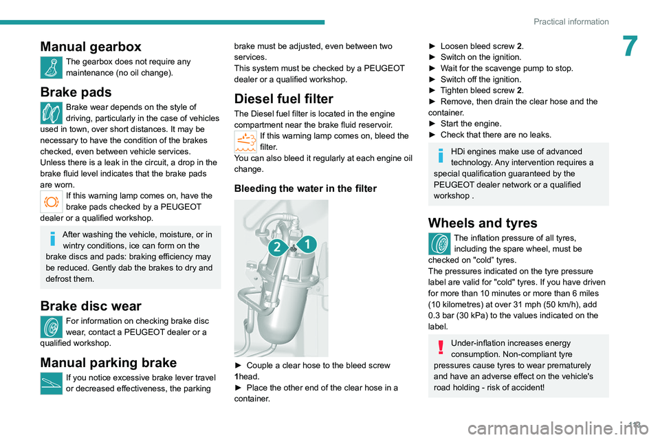
Bleeding the water in the filter
► Couple a clear hose to the bleed screw
1 head.
►
Place the other end of the clear hose in a
container
.
► Loosen bleed screw 2 .
► Switch on the ignition.
►
W
ait for the scavenge pump to stop.
►
Switch off the ignition.
►
T
ighten bleed screw 2.
►
Remove, then drain the clear hose and the
container
.
►
Start the engine.
►
Check that there are no leaks.
HDi engines make use of advanced
technology. Any intervention requires a
special qualification guaranteed by the
PEUGEOT
dealer network or a qualified
workshop .
Wheels and tyres
The inflation pressure of all tyres, including the spare wheel, must be
checked on "cold” tyres.
The pressures indicated on the tyre pressure
label are valid for "cold" tyres. If you have driven
for more than 10 minutes or more than 6 miles
(10 kilometres) at over 31 mph (50
km/h), add
0.3 bar (30 kPa) to the values indicated on the
label.
Under-inflation increases energy
consumption. Non-compliant tyre
pressures cause tyres to wear prematurely
and have an adverse effect on the vehicle's
road holding - risk of accident!
Page 122 of 212
120
In the event of a breakdown
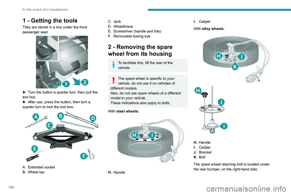
1 - Getting the tools
They are stored in a box under the front
passenger seat.
► Turn the button a quarter turn, then pull the
tool box.
►
After use, press the button, then turn a
quarter turn to lock the tool box.
A. Extended socket
B. Wheel bar
C. Jack
D. Wheelbrace
E. Screwdriver (handle and bits)
F. Removable towing eye
2 - Removing the spare
wheel from its housing
To facilitate this, lift the rear of the
vehicle.
The spare wheel is specific to your vehicle, do not use it on vehicles of
different models.
Also, do not use spare wheels of a different
model to your vehicle.
These indications also apply to bolts.
With steel wheels:
H. Handle I.
Caliper
With alloy wheels:
H. Handle
I. Caliper
J. Bracket
K. Bolt
The spare wheel retaining bolt is located under
the rear bumper, on the right-hand side.
Page 127 of 212
125
In the event of a breakdown
8► Check that the wheel is flat against the floor
of the vehicle and that the notch G
of the winch
is visible.
►
Store the tools and the wheel trim (depending
on version).
For more information on
the Identification markings of the
vehicle, and in particular the tyre pressure
label, refer to the corresponding section.
Changing a bulb
The headlamps have polycarbonate lenses with a protective coating:
►
do not clean them using a dry or
abrasive cloth, nor with a detergent or
solvent product,
►
use a sponge and soapy water or a pH
neutral product,
►
when using a high pressure washer on
persistent marks, do not keep the lance
directed towards the lamps or their edges for
too long, so as not to damage their protective
coating and seals.
Changing a bulb must only be done with
the ignition off and after the lamp has
been switched off for several minutes - Risk
of serious burns!
►
Do not touch the bulb directly with your
fingers, use a lint-free cloth.
It is essential only to use anti-ultraviolet
(UV) type bulbs, so as not to damage the
headlamp.
Always replace a failed bulb with a new bulb
with the same type and specification.
In some weather conditions (e.g. low
temperature or humidity), the presence
of misting on the internal surface of the glass
of the headlamps and rear lamps is normal; it
disappears after the lamps have been on for a
few minutes.
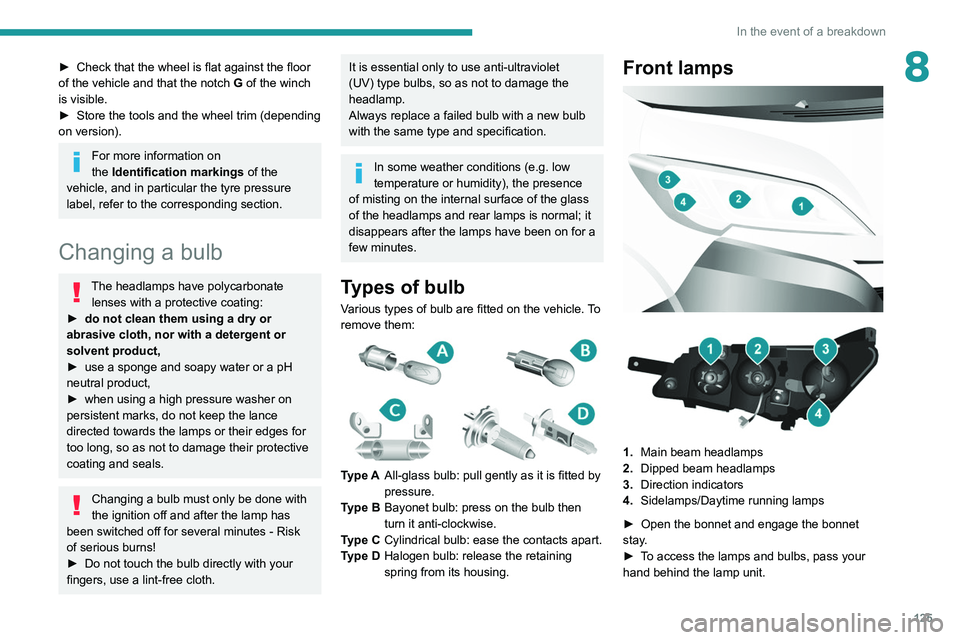
Types of bulb
Various types of bulb are fitted on the vehicle. To
remove them:
Type A All-glass bulb: pull gently as it is fitted by
pressure.
Type B Bayonet bulb: press on the bulb then
turn it anti-clockwise.
Type C Cylindrical bulb: ease the contacts apart.
Type D Halogen bulb: release the retaining
spring from its housing.
Front lamps
1. Main beam headlamps
2. Dipped beam headlamps
3. Direction indicators
4. Sidelamps/Daytime running lamps
►
Open the bonnet and engage the bonnet
stay
.
►
T
o access the lamps and bulbs, pass your
hand behind the lamp unit.
Page 128 of 212
126
In the event of a breakdown
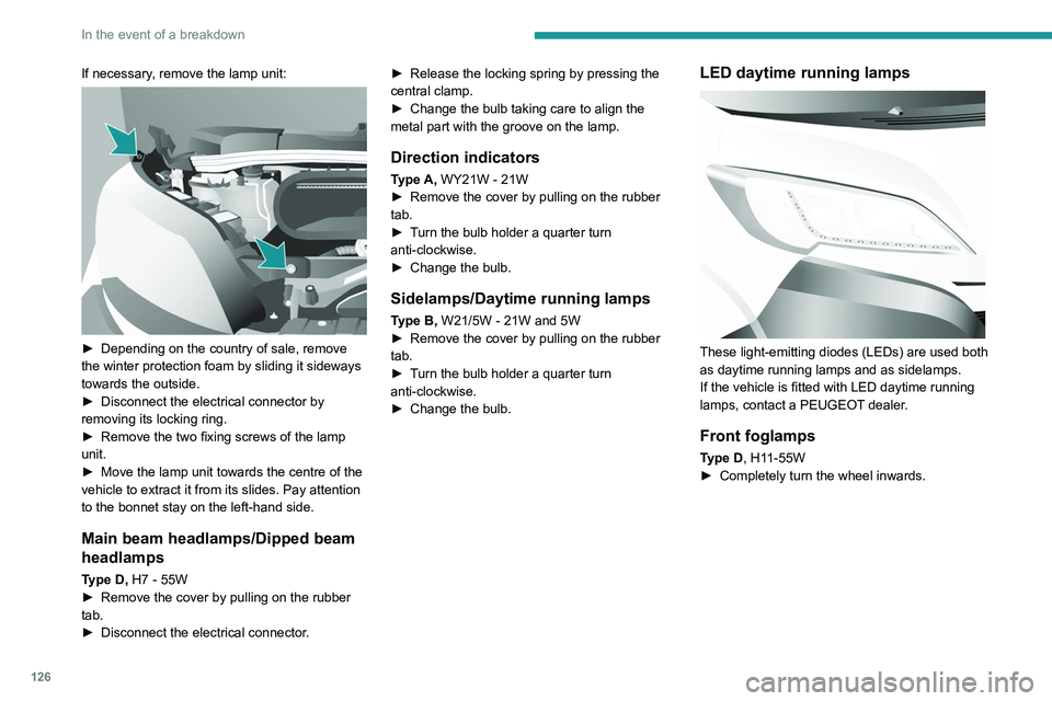
If necessary, remove the lamp unit:
► Depending on the country of sale, remove
the winter protection foam by sliding it sideways
towards the outside.
►
Disconnect the electrical connector by
removing its locking ring.
►
Remove the two fixing screws of the lamp
unit.
►
Move the lamp unit towards the centre of the
vehicle to extract it from its slides. Pay attention
to the bonnet stay on the left-hand side.
Main beam headlamps/Dipped beam
headlamps
Type D, H7 - 55W
► Remove the cover by pulling on the rubber
tab.
►
Disconnect the electrical connector
.►
Release the locking spring by pressing the
central clamp.
►
Change the bulb taking care to align the
metal part with the groove on the lamp.
Direction indicators
Type A, WY21W - 21W
► Remove the cover by pulling on the rubber
tab.
►
T
urn the bulb holder a quarter turn
anti-clockwise.
►
Change the bulb.
Sidelamps/Daytime running lamps
Type B, W21/5W - 21W and 5W
► Remove the cover by pulling on the rubber
tab.
►
T
urn the bulb holder a quarter turn
anti-clockwise.
►
Change the bulb.
LED daytime running lamps
These light-emitting diodes (LEDs) are used both
as daytime running lamps and as sidelamps.
If the vehicle is fitted with LED daytime running
lamps, contact a PEUGEOT dealer.
Front foglamps
Type D, H11-55W
► Completely turn the wheel inwards.