2021 NISSAN FRONTIER ignition
[x] Cancel search: ignitionPage 353 of 492
To shut off the engine in an emergency
situation while driving, perform the follow-
ing procedure:
– Rapidly push the push-button ignitionswitch three consecutive times in less
than 1.5 seconds, or
– Push and hold the push-button ignition switch for more than 2 seconds.TIRE PRESSURE MONITORING
SYSTEM (TPMS)
This vehicle is equipped with TPMS. It moni-
tors tire pressure of all tires except the
spare. When the low tire pressure warning
light is lit, and the CHECK TIRE PRES (pres-
sure) warning message is displayed in the
odometer, one or more of your tires is sig-
nificantly under-inflated. If the vehicle is be-
ing driven with low tire pressure, the TPMS
will activate and warn you of it by the low
tire pressure warning light. This system will
activate only when the vehicle is driven at
speeds above 16 mph (25 km/h). For addi-
tional information, refer to “Warning lights,
indicator lights and audible reminders” in
the “Instruments and Controls” section,
and “Tire Pressure Monitoring System
(TPMS)” in the “Starting and driving” section
of this manual.
Page 374 of 492
•Properly position the mats in the
floorwell using the floor mat posi-
tioning hook. For additional informa-
tion, refer to "Floor mat installation"
in this section.
• Make sure the floor mat does not in-
terfere with pedal operation.
• Periodically check the floor mats to
make sure they are properly
installed.
• Af ter cleaning the vehicle interior,
check the floor mats to make sure
they are properly installed.
The use of Genuine NISSAN floor mats can
extend the life of your vehicle carpet and
make it easier to clean the interior. Mats
should be maintained with regular clean-
ing and replaced if they become exces-
sively worn.
Floor mat installation
Your vehicle is equipped with floor mat po-
sitioning hook(s). The number and shape of
the floor mat positioning hooks for each
seating position varies depending on the
vehicle. When installing Genuine NISSAN floor mats,
follow the installation instructions provided
with the mat and the following:
1. With the ignition in the OFF position, the
shif t lever in P (Park) position and with
the parking brake fully applied, position
the floor mat in the floorwell so that the
floor mat grommet holes are aligned
with the hook(s).
2. Secure the grommet holes into the hook(s) and ensure that the floor mat is
properly positioned.
3. Make sure the floor mat does not inter- fere with pedal operation. With the igni-
tion still in the OFF position, the shif t le-
ver in the P (Park) position and with the
parking brake applied, fully apply and re-
lease all pedals. The floor mat must not
interfere with pedal operation or prevent
the pedal from returning to its normal
position.
It is recommended that you visit a NISSAN
dealer for details about installing the floor
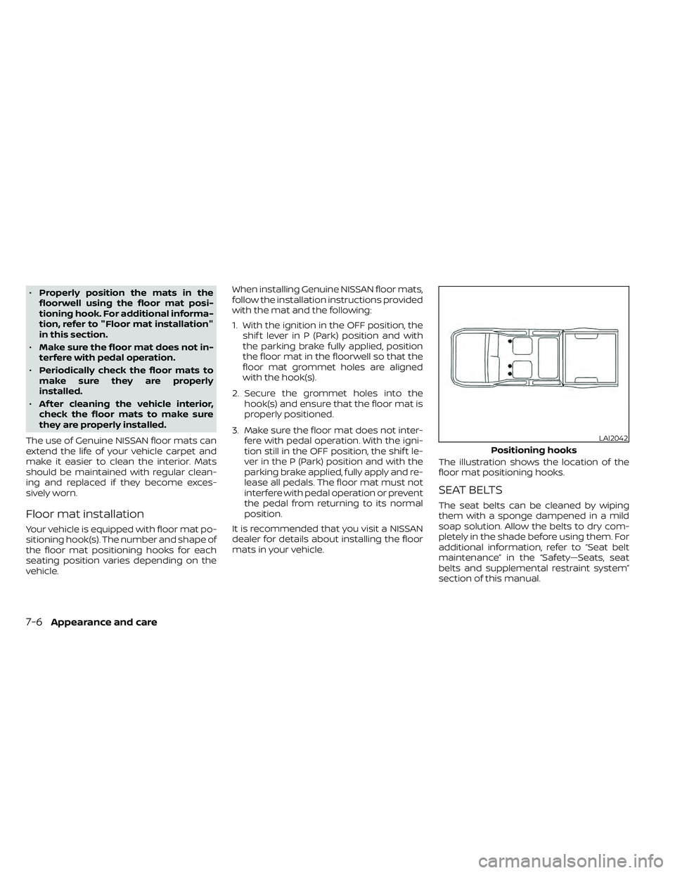
mats in your vehicle. The illustration shows the location of the
floor mat positioning hooks.
SEAT BELTS
The seat belts can be cleaned by wiping
them with a sponge dampened in a mild
soap solution. Allow the belts to dry com-
pletely in the shade before using them. For
additional information, refer to “Seat belt
maintenance” in the “Safety—Seats, seat
belts and supplemental restraint system”
section of this manual.
LAI2042
Positioning hooks
Page 378 of 492
When performing any inspection or main-
tenance work on your vehicle, always take
care to prevent serious accidental injury to
yourself or damage to the vehicle. The fol-
lowing are general precautions which
should be closely observed.
CAUTION
• Do not work under the hood while
the engine is hot. Turn the engine off
and wait until it cools down.
•
Avoid contact with used engine oil and
coolant. Improperly disposed engine
oil, engine coolant and/or other ve-
hicle fluids can damage the environ-
ment. Always conform to local regula-
tions for disposal of vehicle fluid.
• Never leave the engine or the trans-
mission related component harness
connector disconnected while the ig-
nition switch is in the ON position. •
Never connect or disconnect the bat-
tery or any transistorized compo-
nent while the ignition switch is in
the ON position.
This “Do-it-yourself ” section gives instruc-
tions regarding only those items which are
relatively easy for an owner to perform.
A Genuine NISSAN service manual is also
available. For additional information, refer
to “Owner's Manual/Service Manual order
information” in the “Technical and con-
sumer information” section of this manual.
NISSAN recommends the use of Genuine
NISSAN parts or equivalent. The use of parts
that do not meet or exceed NISSAN specifica-
tions, can cause damage to your vehicle, and
have an effect on your warranty coverage. It is
recommended that you visit a NISSAN dealer
parts department who can provide informa-
tion on the proper parts for your vehicle.
You should be aware that incomplete or
improper servicing may result in operating
difficulties or excessive emissions, and
could affect warranty coverage. If in doubt
about any servicing, it is recommended
that you have it done by a NISSAN dealer.
NOTE:
If the battery is dead the transmission will
not manually shif t into other positions.
MAINTENANCE PRECAUTIONS
8-2Do-it-yourself
Page 399 of 492
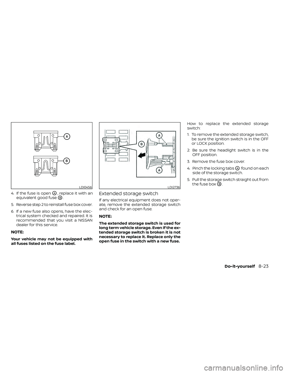
4. If the fuse is openOA, replace it with an
equivalent good fuse
OB.
5. Reverse step 2 to reinstall fuse box cover.
6. If a new fuse also opens, have the elec- trical system checked and repaired. It is
recommended that you visit a NISSAN
dealer for this service.
NOTE:
Your vehicle may not be equipped with
all fuses listed on the fuse label.
Extended storage switch
If any electrical equipment does not oper-
ate, remove the extended storage switch
and check for an open fuse.
NOTE:
The extended storage switch is used for
long term vehicle storage. Even if the ex-
tended storage switch is broken it is not
necessary to replace it. Replace only the
open fuse in the switch with a new fuse. How to replace the extended storage
switch:
1. To remove the extended storage switch,
be sure the ignition switch is in the OFF
or LOCK position.
2. Be sure the headlight switch is in the OFF position.
3. Remove the fuse box cover.
4. Pinch the locking tabs
OAfound on each
side of the storage switch.
5. Pull the storage switch straight out from the fuse box
OB.LDI0456LDI2736
Page 440 of 492
Fuel containing MMT
MMT, or methylcyclopentadienyl manga-
nese tricarbonyl, is an octane boosting ad-
ditive. NISSAN does not recommend the
use of fuel containing MMT. Such fuel may
adversely affect vehicle performance, in-
cluding the emissions control system. Note
that while some fuel pumps label MMT
content, not all do, so you may have to
consult your gasoline retailer for more de-
tails.
Af termarket fuel additives
NISSAN does not recommend the use of
any af termarket fuel additives (for ex-
ample, fuel injector cleaner, octane
booster, intake valve deposit removers,
etc.) which are sold commercially. Many of
these additives intended for gum, varnish
or deposit removal may contain active sol-
vents or similar ingredients that can be
harmful to the fuel system and engine.
Octane rating tips
Using unleaded gasoline with an octane
rating lower than recommended can
cause persistent, heavy “spark knock.”
(“Spark knock” is a metallic rapping
noise.) If severe, this can lead to engine
damage. If you detect a persistent heavy
spark knock even when using gasoline
of the stated octane rating, or if you hear
steady spark knock while holding a
steady speed on level roads, it is recom-
mended that you have a NISSAN dealer
correct the condition. Failure to correct
the condition is misuse of the vehicle, for
which NISSAN is not responsible.
Incorrect ignition timing may result in
spark knock, af ter-run and/or overheating,
which may cause excessive fuel consump-
tion or engine damage. If any of the above
symptoms are encountered, have your ve-
hicle checked. It is recommended that you
visit a NISSAN dealer for servicing.However, now and then you may notice
light spark knock for a short time while
accelerating or driving up hills. This is not
a cause for concern, because you get the
greatest fuel benefit when there is light
spark knock for a short time under heavy
engine load.
10-6Technical and consumer information
Page 443 of 492
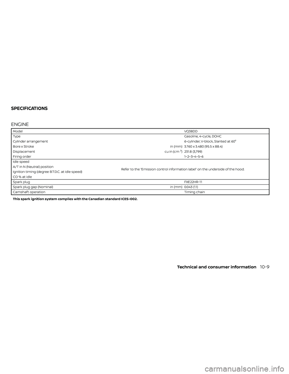
ENGINE
ModelVQ38DD
Type Gasoline, 4-cycle, DOHC
Cylinder arrangement 6-cylinder, V-block, Slanted at 60°
Bore x Stroke in (mm) 3.760 x 3.480 (95.5 x 88.4)
Displacement cu in (cm
3) 231.8 (3,799)
Firing order 1–2–3–4–5–6
Idle speed
Refer to the “Emission control information label” on the underside of the hood.
A/T in N (Neutral) position
Ignition timing (degree B.T.D.C. at idle speed)
CO%atidle
Spark plug
FXE22HR-11
Spark plug gap (Nominal) in (mm) 0.043 (1.1)
Camshaf t operation Timing chain
This spark ignition system complies with the Canadian standard ICES-002.
SPECIFICATIONS
Technical and consumer information10-9
Page 465 of 492
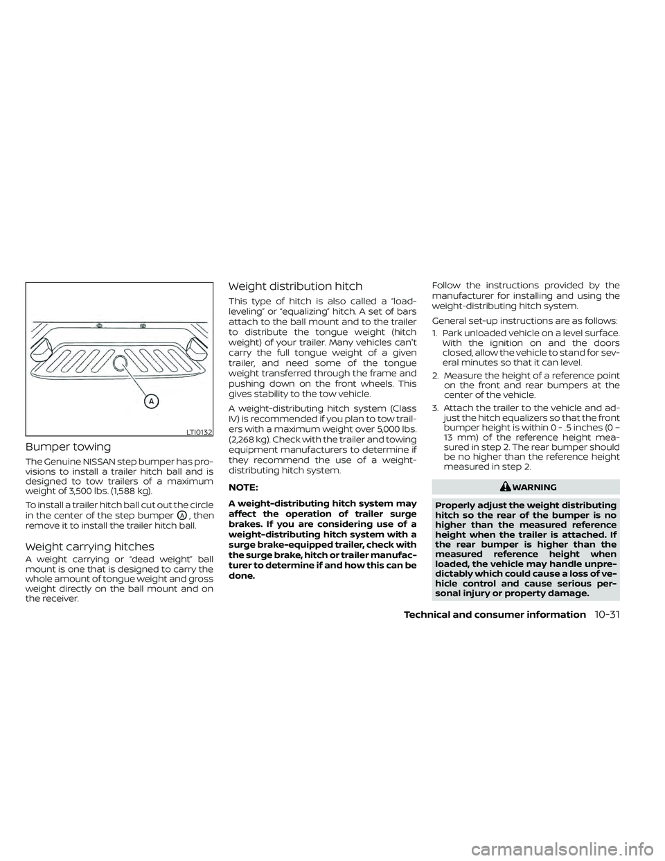
Bumper towing
The Genuine NISSAN step bumper has pro-
visions to install a trailer hitch ball and is
designed to tow trailers of a maximum
weight of 3,500 lbs. (1,588 kg).
To install a trailer hitch ball cut out the circle
in the center of the step bumper
OA, then
remove it to install the trailer hitch ball.
Weight carrying hitches
A weight carrying or “dead weight” ball
mount is one that is designed to carry the
whole amount of tongue weight and gross
weight directly on the ball mount and on
the receiver.
Weight distribution hitch
This type of hitch is also called a “load-
leveling” or “equalizing” hitch. A set of bars
attach to the ball mount and to the trailer
to distribute the tongue weight (hitch
weight) of your trailer. Many vehicles can't
carry the full tongue weight of a given
trailer, and need some of the tongue
weight transferred through the frame and
pushing down on the front wheels. This
gives stability to the tow vehicle.
A weight-distributing hitch system (Class
IV) is recommended if you plan to tow trail-
ers with a maximum weight over 5,000 lbs.
(2,268 kg). Check with the trailer and towing
equipment manufacturers to determine if
they recommend the use of a weight-
distributing hitch system.
NOTE:
A weight-distributing hitch system may
affect the operation of trailer surge
brakes. If you are considering use of a
weight-distributing hitch system with a
surge brake-equipped trailer, check with
the surge brake, hitch or trailer manufac-
turer to determine if and how this can be
done. Follow the instructions provided by the
manufacturer for installing and using the
weight-distributing hitch system.
General set-up instructions are as follows:
1. Park unloaded vehicle on a level surface.
With the ignition on and the doors
closed, allow the vehicle to stand for sev-
eral minutes so that it can level.
2. Measure the height of a reference point on the front and rear bumpers at the
center of the vehicle.
3. Attach the trailer to the vehicle and ad- just the hitch equalizers so that the front
bumper height is within0-.5inches (0 –
13 mm) of the reference height mea-
sured in step 2. The rear bumper should
be no higher than the reference height
measured in step 2.
Page 474 of 492
WARNING
A vehicle equipped with Four-Wheel
Drive (4WD) should never be tested us-
ing a two wheel dynamometer (such as
the dynamometers used by some
states for emissions testing), or similar
equipment. Make sure you inform the
test facility personnel that your vehicle
is equipped with 4WD before it is placed
on a dynamometer. Using the wrong
test equipment may result in transmis-
sion damage or unexpected vehicle
movement which could result in seri-
ous vehicle damage or personal injury.
Due to legal requirements in some states
and Canadian Provinces, your vehicle may
be required to be in what is called the
“ready condition” for an Inspection/
Maintenance (I/M) test of the emission
control system.
The vehicle is set to the “ready condition”
when it is driven through certain driving
patterns. Usually, the ready condition can
be obtained by ordinary usage of the ve-
hicle. If a powertrain system component is re-
paired or the battery is disconnected, the
vehicle may be reset to a “not ready ” condi-
tion. Before taking the I/M test, check the
vehicle's inspection/maintenance test
readiness condition. Place the ignition
switch in the ON position without starting
the engine. If the Malfunction Indicator
Light (MIL) comes on steady for 20 seconds
and then blinks for 10 seconds, the I/M test
condition is “not ready”. If the MIL does not
blink af ter 20 seconds, the I/M test condi-
tion is “ready ”. It is recommended that you
visit a NISSAN dealer to set the “ready con-
dition” or to prepare the vehicle for testing.
This vehicle is equipped with an Event Data
Recorder (EDR). The main purpose of an
EDR is to record, in certain crash or near
crash-like situations, such as an air bag
deployment or hitting a road obstacle, data
that will assist in understanding how a ve-
hicle's systems performed. The EDR is de-
signed to record data related to vehicle dy-
namics and safety systems for a short
period of time, typically 30 seconds or less.
The EDR in this vehicle is designed to re-
cord such data as:
• How various systems in your vehicle were
operating;
• Whether or not the driver and passenger safety belts were buckled/fastened;
• How far (if at all) the driver was depress- ing the accelerator and/or brake pedal;
and,
• How fast the vehicle was traveling.
• Sounds are not recorded.
READINESS FOR INSPECTION/
MAINTENANCE (I/M) TEST EVENT DATA RECORDERS (EDR)
10-40Technical and consumer information