2021 MERCEDES-BENZ GLC COUPE trailer
[x] Cancel search: trailerPage 248 of 481

*
NO
TEDama getothere ar bumper from
ins talling adap ter cables or adapte r plugs The
following parts could be damaged when
swiveling the ball neck fully electrically:
R Bumper
R Adapter cable
R Adapter plug #
Alw aysre mo vethe adap ter cable or
adapte r plug before swiveling the ball
neck fully electrically. #
Secure the trailer against rolling away. #
Disconnect the electrical connection
between theve hicle and the trailer. #
Uncouple the trailer. #
Place the co ver cap on the ball head. Bicycle
rackfunction &
WARNING Risk of an accident when
using the bicycle rack incor rectly
The bicycle rack may become de tach ed from
th eve hicle in thefo llowing cases:
R the permissible load capacity of the
trailer hitch is exceeded.
R the bicycle rack is used incor rectl y.
R the bicycle rack is secured tothe ball
neck beneath the ball head.
Obser vethefo llowing foryo ur ow n sa fety
and that of other road users:
R always adhere tothe permissible load
capacity of the trailer hitch.
R only use the bicycle rack totranspo rt
bicycles.
R always mount the bicycle rack properly by
attaching tothe ball head and the ball
neck guide pin, if possible. R
when transporting four bic ycles, alw ays
use bic ycle rack s which ha veadditional
suppo rton the ball neck guide pin.
R only use bicycle rack s appr ovedby
Mercedes-Benz.
R always obser vethe bicycle rack operating
instructions. *
NO
TEDama geto, or cra cks on, the
trailer hitch due tounsuitable bic ycle
ra ck s or bicycle rack s being used incor‐
re ctly #
use only bicycle rack s appr ovedby
Mercedes-Benz. *
NO
TEIncreased risk of damage toprop‐
erty due tofolded-out ball neck #
When the trailer is not coupled or the
bicycle rack is attached, fold in the ball
neck or, in the case of a fully electric
trailer hitch, retract the ball nec k. Driving and pa
rking 245
Page 249 of 481

Tr
ailer hit ch(examp le with additional guide pin)
Depending on the bicycle rack 's design, dif fere nt
numbe rsof bicycles can be transpor ted.
The following bicycle rack designs are possible:
R When mounted byattaching toball head 1,
th e maximum load capacity is 75kg.Yo u can
transport up tothre e bicycles. R
When mounted on ball head 1and guide
pin 2, the maximum load capacity is
10 0kg .Yo u can transpo rtup tofour bicy‐
cles.
The maximum load capacity is calculated from
th ewe ight of the bicycle rack and the bicycle
ra ck load.
Obser vethe no tes on driving with a roof load,
trailer or fully laden vehicle (/ page157).
When using a bicyc lerack , set the tyre pressure
fo r increased load on there ar axle of theve hicle.
Fu rther information on the tyre pressure can be
fo und in the tyre pressure table (/ page 337).
Note s on loading
The larger the dis tance between the load's
cent reof gr avity and the ball head, the greater
th e load on the trailer hitch.
Obser vethefo llowing no tes:
R mount heavy bicycles as close totheve hicle
as possible
R always distribute the load on the bicycle rack
as eve nly as possible across theve hicle's
longitudinal axis Mercedes-Benz
recommends removing all
de tach able parts from bicycles (e.g. bask ets,
ch ild seats, rech arge able bat teries) before load‐
ing them onto the bicycle rack . This will impr ove
th e aerodynamic resis tance and centre of gr avity
of the bicycle rack.
Alw ays secure the bicycles toprev ent them from
moving around and check them at regular inter‐
va ls to ensure that they are secure.
Do not use tarp aulins or other co vers. The driv‐
ing characteristics and rear view may be
impaired. In addition, aerodynamic resis tance
and the load on the trailer hitch will increase. 246
Driving and pa rking
Page 250 of 481
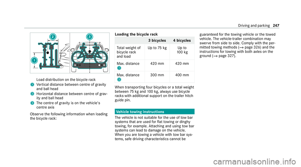
Load distribution on
the bicycle rack
1 Vertical dis tance between centre of gr avity
and ball head
2 Horizon tal dis tance between centre of gr av‐
ity and ball head
3 The centre of gr avity is on theve hicle's
centre axis
Obse rveth efo llowing information when loading
th e bicycle rack: Loading
the bicycle rack 3 bicycles 4 bicycles
To talwe ight of
bicycle rack
and load Up
to75 kg Up to
10 0kg
Max. dis tance
1 420 mm 420 mm
Max. di stance
2 300 mm 400 mm When transpo
rting four bic ycles or a totalwe ight
between 75kgand 100kg , alw ays use bicycle
ra ck s with additional support on the trailer hitch
guide pin. Ve
hicle towing instructions
The vehicle is not suitable forth e use of tow bar
sy stems that are used forflat towing or ding hy
to wing, forex ample. Attach ing and using tow bar
sy stems can lead todamage on theve hicle.
When you are towing a vehicle with tow bar sys‐
te ms, safe driving characteristics cannot be guaranteed
forth eto wing vehicle or theto wed
ve hicle. The vehicle-trailer combination may
swer vefrom side toside. Comply with the per‐
mitted towing me thods (/ page 326) and the
instructions forto wing with bo thaxles on the
ground (/ page 327). Driving and parking
247
Page 313 of 481
Sensors
R
Clean the sensors in the front and rear
bumpers with a soft clo thand car shampoo
(/ page 184).
R When using a high -pressure cleaner,maintain
a minimum dis tance of 30 cm.
Ru nning boards
R Use wate r and acid-free cleaning agents.
R Do not clean the aluminium trim insert of the
ru nning board wi thalkaline or acidic cleaning
agents such as wheel cleaners. Do not use
acidic alloy wheel cleaners toremo vebrake
dust. The aluminium trim inserts could other‐
wise be damaged.
Re versing camera and 360° Camera
R Open the camera co ver with the multimedia
sy stem (/ page 228).
R Use clean water and a soft clo thtoclean the
came ralens.
R Do not use a high-pressure cleaner. Ta
ilpipes
R Clean with a cleaning agent recommended
fo r Mercedes-Benz, especially inthe winter
and af terwa shing theve hicle.
R Do not use acidic cleaning agents.
Tr ailer hitch
R Obse rveth e no tes on care in the trailer hitch
manufacturer's operating instructions.
R Do not clean the ball neck with a high-pres‐
sure cleaner or solvent.
R Remo vetraces of rust on the ball, forex am‐
ple, with a wire brush.
R Remo vedirt with a lint-free clo th.
R After cleaning, lightly oil or grease the ball
head.
% Before using trailers with anti- torsional cou‐
pling, obser vethe manufacturer's operating
instructions. Note
s on care of the interior &
WARNING Risk of injury from plastic
parts breaking off af terth e use of sol‐
ve nt-based care products
Ca reand cleaning products con taining sol‐
ve nts can cause su rfaces in the cockpit to
become porous. When the airbags are
deplo yed, plastic parts may break away. #
Do not use any care or cleaning prod‐
ucts containing sol vents toclean the
cockpit. &
WARNING Risk of injury or death from
bleached seat belts
Bleaching or dyeing seat belts can se verely
we aken them.
This can, forex ample, cause seat belts to
te ar or fail in an accident. #
Never blea chor dye seat belts. To
avo id damage totheve hicle, obser vethefo l‐
lowing no tes on cleaning and care: 310
Maintenance and care
Page 331 of 481
#
Atowing dis tance of 50 km must not be
exc eeded. &
WARNING Risk of accident when towing
a ve hicle which is too heavy
If ano ther vehicle is tow- star ted or towed
aw ay, its weight must not exceed the permis‐
sible gross mass of your ow nve hicle, other‐
wise thefo llowing could occur:
R theto wing eye may become de tach ed.
R theve hicle/trailer combination may
swer veoreve nov erturn. #
If ano ther vehicle is tow- star ted or
to we daw ay, its weight must not exceed
th e permissible gross mass of your own
ve hicle. If a
vehicle must be tow- star ted or towe daw ay,
its permissible gross weight must not exceed the
permissible gross weight of theto wing vehicle. #
Information on the permissible gross mass of
th eve hicle can be found on theve hicle iden‐
tification plate (/ page 355). #
Vehicles with automatic transmission: do
not open the driver's door or front passenger
door, otherwise the automatic transmission
automatically shifts toposition j. #
Fittheto wing eye (/ page 330). #
Fasten theto w bar.
* NO
TEDama gedue toincor rect connec‐
tion of theto w bar #
Onlyconnect theto w rope or tow bar to
th eto wing eyes. #
Deactivate the automatic locking mechanism
(/ page 79). #
Do not activate the HOLD function. #
Deactivate tow- aw ay protection
(/ page 94). #
Deactivate Active Brake Assi st
( / page 210). #
Vehicles with automatic transmission:
shift the automatic transmission toposition
i. #
Release the electric parking brake. &
WARNING Risk of accident due tolimi‐
te d saf ety-re lated functions during the
to wing process
Saf ety-re lated functions are limited or no lon‐
ge rav ailable in thefo llowing situations:
R the ignition is switched off.
R the brake sy stem or po werst eering sys‐
te m is malfunctioning.
R the energy supply or the on-board electri‐
cal sy stem is malfunctioning.
When your vehicle is then towe daw ay, signif‐
icantly more ef fort may be requ ired tosteer
and brake than is norm allyrequ ired. #
Use a tow bar. #
Make sure that thesteering wheel can
mo vefreely before towing theve hicle
aw ay. 328
Breakdown assis tance
Page 332 of 481
*
NO
TEDama gedue toexcessive tracti ve
po wer If
yo u pull away sharpl y,the tractive po wer
may be too high and theve hicles could be
damaged. #
Pull away slowly and smoo thly. Loading the
vehicle for transport #
Obser vethe no tes on towing away
( / page 327). #
Connect theto wing device totheto wing eye
in order toload theve hicle.
% You can also attach theto w bar tothe trailer
hitch. #
Vehicles with automatic transmission:
shift the automatic transmission toposition
i.
% Ve
hicles with automatic transmission:
th e automatic transmission may be loc ked in
position jintheeve nt of damage tothe
electrical sy stem. Toshift toi , pr ovide the on-board electrical sy
stem with po wer
( / page 325). #
Load theve hicle onto the transpor ter. #
Vehicles with automatic transmission:
shift the automatic transmission toposition
j. #
Use the electric parking brake tosecure the
ve hicle against rolling away. #
Only secure theve hicle bythe wheels.
Ve hicles with ADS PLUS (Adaptive Damping
Sy stem PLUS) &
WARNING Risk of an accident when
transporting vehicles with Adaptive
Damping Sy stem PLUS
When transporting vehicles with Adaptive
Damping Sy stem PLUS, theve hicle/trailer
combination may begin torock andstart to
skid. #
Load theve hicle cor rectly onto the
transpo rter. #
Secure theve hicle on all four wheels
with suitable tensioning stra ps. #
Do not exceed the maximum permissi‐
ble speed of 60 km/h when transport‐
ing. *
NO
TEDama getotheve hicle from secur‐
ing it incor rectly #
After loading, theve hicle must be
secured on all four wheels. Otherwise,
th eve hicle could be damaged. #
A minimum dis tance of 20 cm up wards
and 10cm down wards must be kept to
th e transport platform. #
Secure theve hicle on all four wheels af ter
loading. Breakdown assis
tance 329
Page 333 of 481
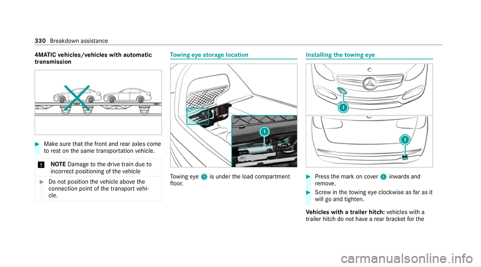
4MATIC
vehicles/ve hicles with automatic
transmission #
Make sure that the front and rear axles come
to rest on the same transpor tation vehicle.
* NO
TEDama getothe drive train due to
incor rect positioning of theve hicle #
Do not position theve hicle abo vethe
connection point of the transport vehi‐
cle. To
wing eyesto rage location To
wing eye1 is under the load compartment
fl oor. Installing
theto wing eye #
Press the mark on co ver1 inwa rds and
re mo ve. #
Screw intheto wing eyeclockwise as far as it
will go and tighten.
Ve hicles with a trailer hitch: vehicles with a
trailer hitch do not ha veare ar brac ketfo rthe 330
Breakdown assis tance
Page 334 of 481

to
wing eye. Fasten theto w bar tothe trailer
hitch. #
Make sure that co ver1 engages in the
bumper when youre mo vetheto wing eye.
* NO
TEDama getotheve hicle due to
incor rect use of theto wing eye When a
towing eye is used toreco ver a vehi‐
cle, theve hicle may be damaged in the proc‐
ess. #
Only use theto wing eyeto to waw ay or
to w start theve hicle. *
NO
TEDama getotheve hicle due to
incor rect use of theto wing eye or trailer
hitch When a
towing eye or trailer hitch is used to
re co ver a vehicle, theve hicle may be dam‐
aged in the process. #
Do not use theto wing eye or trailer
hitch to towtheve hicle during reco very. To
w starting theve hicle (eme rgency engine
st art) Ve
hicles with automatic transmission
* NO
TEDama getothe automatic trans‐
mission due to tow-starting The automatic transmission may be damaged
in
the process of tow- starting vehicles with
automatic transmission. #
Vehicles with automatic transmission
must not be tow- star ted. #
Vehicles with automatic transmission must
not be tow- star ted. Electrical fuses
Note
s on electrical fuses &
WARNING Risk of accident and inju ry
due to ov erloaded lines
If yo u manipulate or bridge a faulty fuse or if
yo ure place it with a fuse with a higher amperage,
the electric line could be overloa‐
ded.
This could result in a fire. #
Alw aysre place faulty fuses with speci‐
fi ed new fuses conta iningthe cor rect
amperage. *
NO
TEDama gedue toincor rect fuses Electrical components or sy
stems may be
damaged byincor rect fuses, or their func‐
tionality may be significant lyimpaired. #
Only use fuses that ha vebeen appr oved
by Mercedes-Benz and which ha vethe
cor rect fuse rating. Blown fuses mu
stbe replaced with fuses of the
same rating, which you can recognise bythe col‐
our and the label. The fuse ratings and fu rther
information tobe obser ved can be found in the
fuse assignment diagram.
Fu se assignment diag ram: onthe fuse box in
th e load compartment (/ page 334). Breakdown assis
tance 331