2021 MERCEDES-BENZ GLC COUPE dimensions
[x] Cancel search: dimensionsPage 230 of 481

1
Guide line of extern al vehicle dimensions
with outside mir rors folded out
2 Marker of the wheel conta ct points
Sy stem failure
If th e sy stem is not ready for operation, thefo l‐
lowing message appears in the media display: Sy
stem limits
The 360° Camera will not function or will only
partially function in thefo llowing situations:
R The doors are open.
R the outside mir rors are folded in.
R The tailgate is open.
R There is heavy rain, snow or fog.
R The light conditions are poor, e.g. at night.
R Cameras, or vehicle components in which
th e cameras are fitted, are dama ged, dirty or
co vered. Obser vethe information on vehicle
sensors and cameras (/ page184).
% Do not use the 360° Camera under such cir‐
cums tances. You could otherwise injure oth‐
ers or collide with objects when parking the
ve hicle.
Fo rte ch nical reasons, thest andard height of the
ve hicle may be altered if theve hicle is car rying a
heavy load and can result in inaccuracies in the
guide lines and in the display of thege nerated
ima ges. %
The contra stof the display may be impaired
by abrupt, direct sunlight or by other light
sources, e.g. when driving out of a garage . In
th is case, pay particular attention.
% Have the display repaired or replaced if, for
ex ample, pixel er rors considerably restrict its
use.
See the no tes on cleaning the 360° Camera
(/ page 309).
Calling up the view of the 360° Camera
using reve rsege ar
Re quirements:
R The Auto reversing camera function is activa‐
te d in the multimedia sy stem (/ page 228). #
Shift toreve rsege ar. #
Select the desired view in the multimedia
sy stem (/ page 224). #
If, af ter shifting toreve rsege ar, the image of
th ere ve rsing camera is not shown: switch off
th e ignition, press and hold thec button,
switch on the ignition and engage reve rse
ge ar again. Driving and parking
227
Page 309 of 481
*
NO
TEDama gefrom auto matic braking If one of
thefo llowing functions is switched
on, theve hicle brakes automatically in cer‐
ta in situations:
R Active Brake Assi st
R Active Dis tance Assi stDISTRONIC
R HOLD function
R Active Parking Assist
To avo id damage totheve hicle, deactivate
th ese sy stems in thefo llowing or similar sit‐
uations: #
during towing #
in a car wash *
NO
TEDama gedue tounsuitable car
wa sh #
Before driving into a car wash make
sure that the car wash is suitable for
th eve hicle dimensions. #
Ensure there is suf ficient ground clear‐
ance between the underbody and the
guide rails of the car wash. #
Ensure that the clearance width of the
car wash, in particular the width of the
guide rails, is suf ficient. To
avo id damage to yourvehicle when using a
car wash, ensure thefo llowing beforehand:
R Active Dis tance Assi stDISTRONIC is deacti‐
va ted.
R The HOLD function is switched off.
R The 360° Camera or there ve rsing camera is
switched off.
R The side windo wsand sliding sun roof are
comple tely closed.
R The bl owerfo rth eve ntilation/heating is
switched off.
R The windsc reen wiper switch is in position
g.
R The key is at a minimum dis tance of 3 m
aw ay from theve hicle. Otherwise theta ilgate
could open unin tentional ly. R
In automatic car washes with con veyo r sys‐
te ms:
- Neutral iis engaged.
- Ifyo uwo uld like tolea vetheve hicle while
it is being washed, make sure theke y is
located in theve hicle. The park position
j isotherwise automatically engaged.
% If, af terth e car wash, youre mo vethewax
from the windscreen and wiper rubbers, this
will pr event smearing and reduce wiper
noise. Information on using a high-p
ressure cleaner &
WARNING Risk of an accident when
using high-pressure cleane rswith round-
spray nozzles
The wate r jet can cause extern ally invisible
damage.
Components damaged in this wa y may unex‐
pec tedly fail. 306
Maintenance and care
Page 347 of 481

#
Only inter change the front and rear
wheels if the wheels and tyres ha vethe
same dimensions. Inter
changing the front and rear wheels if the
wheels or tyres ha vediffere nt dimensions can
re nder thege neral operating pe rmit in valid.
The wear pat tern s on the front and rear wheels
dif fer:
R front wheels wear more on the tyre shoulder
R rear wheels wear more in the cent reofthe
tyre
Do not drive wi thtyres that ha vetoo little tread
dep th. This significantly reduces traction on wet
ro ads (aquaplaning).
On vehicles with the same front and rear wheel
size, you can inter change the wheels every
5000 to10,000 km, depending on thewe ar.
Ensure the direction of rotation is maintained for
th e wheels.
Obser vethe instructions and saf ety no tes on
"Changing a wheel" when doing so
(/ page 345). Note
s onstoring wheels When
storing wheels, obser vethefo llowing
no tes:
R Afterre moving wheels, store them in a cool,
dry and preferably dark place.
R Protect the tyres from conta ct withoil,
grease or fuel. Overview of
the ty re-change tool kit *
NO
TEMercedes-AMG vehicles #
Obser vethe no tes in the Supplement.
Yo u could otherwise failto recognise
dangers. *
NO
TEPlug-in hybrid #
Obser vethe no tes in the Supplement.
Yo u could otherwise failto recognise
dangers. Apa
rtfrom some countr y-specific variants, vehi‐
cles are not equipped with a tyre-change tool kit. Fo
r more information on which tyre-changing
to ols are required and appr oved for per form ing a
wheel change on your vehicle, consult a qualified
specialist workshop.
Yo ure qu ire thefo llowing tools, forex ample, to
ch ange a wheel:
R Jack
R Chock
R Wheel wrench
R Cent ring pin
% The jack weighs appr oximately 3.4 kg.
The maximum load capacity of the jack can
be found on thest icke r af fixe dto the jac k.
The jack is maintenance-free. If there is a
malfunction, please conta ct aqualified spe‐
cialist workshop.
The tyre-change tool kit is located under the load
compartment floor.
% Depending on the model, the tyre change
to ol kit may be located in other positions
under the load compartment floor. 344
Wheels and tyres
Page 353 of 481
#
Tighten the wheel bolts evenly in a diagonal
pattern in the order indicated 1to5 to
th e specified tightening torque of 150 Nm. &
WARNING Risk of accident due toincor‐
re ct tigh tening torque
The wheels could come loose if the wheel
bolts or wheel nuts are not tightened tothe
prescribed torque. #
Ensu rethat the wheel bolts or wheel
nuts are tightened tothe prescribed
tightening torque. #
Ifyo u are not sure, do not mo vethe
ve hicle. Contact a qualified specialist
wo rkshop and ha vethe tightening tor‐
qu ech ecked immediately. #
Check the tyre pressure of the newly fitted
wheel and adjust it if necessa ry.
% The following does not apply if the new
wheel is an emer gency spa rewheel. #
Vehicles with tyre pressure loss warning
sy stem: restart the tyre pressure loss warn‐
ing sy stem (/ page 340). #
Vehicles with a tyre pressure monitoring
sy stem: restart the tyre pressure monitoring
sy stem (/ page 339). Emer
gency spare wheel Note
s onthe emer gency spare wheel &
WARNING Risk of accident caused by
incor rect wheel and tyre dimensions
The wheel or tyre size and the tyre type of
th e emer gency spa rewheel or spare wheel
and the wheel tobe replaced may dif fer. The
emer gency spa rewheel or spare wheel can
significantly impair driving characteristics of
th eve hicle.
To preve nt hazardous situations: #
Drive carefully. #
Neverfit more than one emer gency
spa rewheel or spare wheel that dif fers
in size. #
Only use an emer gency spa rewheel or
spare wheel brief ly. #
Do not deacti vate ESP ®
. #
Have the emer gency spa rewheel or
spare wheel of a dif fere nt size replaced
at the nearest qualified specialist work‐
shop. The new wheel must ha vethe
cor rect dimensions. %
The emergency spa rewheel is fastened in
th e load compartment under the load com‐
partment floor.
Obser vethefo llowing no tes on fitting an emer‐
ge ncy spa rewheel:
R Check the tyre pressure of the emer gency
spa rewheel fitted. Co rrect the pressure as
necessar y.
R The maximum permissible speed with an
emer gency spa rewheel fitted is 80 km/h. 350
Wheels and tyres
Page 369 of 481
#
Make sure that no windscre enwasher
concentrate spills out next tothefiller
opening. *
NO
TEDama getotheex terior lighting
due tounsuitable windsc reen washer
fl uid Uns
uitable windsc reen washer fluids may
damage the plastic sur face of theex terior
lighting. #
Only use windscreen washer fluids
which are also suitable for use on plas‐
tic sur faces, e.g. MB SummerFit or MB
Wi nterFit. *
NO
TEBlocked spr aynozzles caused by
mixing windscreen washer fluids #
Do not mix MB SummerFit and MB Win‐
te rFit with other windscreen washer flu‐
ids. Do not use distilled or de-ionised
water.Other‐
wise, thefill le vel sensor may be triggered er ro‐
neously.
Re commended windscreen washer fluid:
R abo vefreezing point: e.g. MB SummerFit
R below freezing point: e.g. MB WinterFit
Fo rth e cor rect mixing ratio, referto the informa‐
tion on the antif reeze contai ner.
Mix washer fluid with windsc reen washer fluid all
ye ar round. Ve
hicle data Ve
hicle dimensions The heights specifi
ed mayvary as a result of the
fo llowing factors:
R tyres
R load
R condition of the suspension
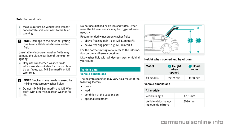
R optional equipment Height when opened and headroom
Model
1 1Height
when
opened 2 2
Head‐
ro om
All models 2209 mm 1933 mm Ve
hicle dimensions All models
Ve
hicle lengt h4 731 mm
Ve hicle width includ‐
ing outside mir rors 2096 mm366
Tech nical da ta
Page 370 of 481

All models
Ve
hicle width exclud‐
ing outside mir rors 18
90 mm
Ve hicle height 1600 mm
Wheelbase 2873 mm We
ights and loads Please obser
vethefo llowing no tesfo rth e speci‐
fi ed vehicle data:
R Items of optional equipment increase the
unladen weight and reduce the pa yload.
R Vehicle-specific weight information can be
fo und on theve hicle identification plate
(/ page 355).
Obser vetheve hicle data specified below :
optional equipment increases the unladen
we ight and reduces the pa yload. Model
Maximumroof load
All models 75kg Tr
ailer hitch Gene
ral no tes on the trailer hit ch Modifications
tothe engine cooling sy stem may
be necessar y,depending on theve hicle model.
The retrofitting of a trailer hitch is only pe rmissi‐
ble if a towing capacity is specified in your vehi‐
cle documents.
Fu rther information can be obtained at a quali‐
fi ed specialist workshop. Mounting dimensions
1
Fastening points
2 Overhang dimension
3 Rear axle centre line Te
ch nical da ta367
Page 470 of 481
St
ow age space
Armrest.................................................. 111
Centre console....................................... 111
Door....................................................... 111
Glo vecompa rtment................................ 111
Stre etnames and house numbers
Displaying..............................................2 70
Suggestions Configuri ng........................................... 262
Sulphur content........................................ 359
Sur round lighting
Switching on/of f................................... 13 5
Sur round View
see 360° Camera
Suspension Adjusting thech assis le vel (AIR
BO DY CONTROL)...................................2 19
Suspension see AIR BODY CONTROL
SV HC (substances of very high con‐
cern) ............................................................. 32
Switch-off del aytime
Exterio r.................................................. 13 5Interior..................................................
13 6
Synchronisation function Activating/deactivating (control
panel).................................................... 14 4
Ac tivating/deactivating (MBUX mul‐
timedia sy stem).....................................1 44
Sy stem settings
Overview of the sy stem settings
menu.....................................................2 62
Re set function (MBUX multimedia
sy stem)................................................. 266 T
Ta ilgate
Closing.................................................... 81
HANDS-FREE ACCES S............................. 84
Limiting the opening angle......................85
Opening................................................... 81
Un locking (emer gency key)..................... 86
Ta ilpipes (care)......................................... .309
Ta ke -back of end-of-life vehicles
Pr otection of the environmen t................. 22
Ta nk content
Ad Blue ®
................................................ 362 Fu
el........................................................3 61
Re ser ve(fuel)........................................ 361
Te ch nical data
Axle load (trailer operation)...................3 69
Fa stening points (trailer hitch)............... 367
Information............................................ 353
Mounting dimensions (trailer hitch)....... 367
No tes (trailer hitch)............................... 367
Overhang dimension (trailer hitch)........3 67
Re gulatory radio identification.............. 355
To ngue weight...................................... .368
To wing capacity (trailer operation )........ 368
Ve hicle identification plate....................3 55
Te lephone
Connecting a mobile phone (Passk ey)... 276
Connecting a mobile phone (Secure
Simple Pairing)...................................... 276
Fu nctions in thete lephone men u.......... 276
No tes..................................................... 273
Operating modes...................................2 75
Te lephone menu overvie w..................... 275
Wi reless charging (mobile phone).......... 124
Te lephony operating modes
Blue tooth ®
Te lephony........................... .275 Index
467
Page 471 of 481
Te
mp erature
Setting theve hicle interior temp era‐
ture........................................................ 14 2
Themes Fastening.............................................. 262
Through-loading feature
see Seat
Ti e-d owney es ............................................ 11 5
TIREFIT kit Declaration of conformity........................ 30
Storage location.....................................3 16
Using..................................................... 317
To ngue weight .......................................... .368
To ol
see Vehicle tool kit
To pTe ther.................................................... 64
To pping up
To pping up AdBlue ®
............................... 175
To uch Control
On-board computer............................... 250
Operating.............................................. 256 To
uchpad
Operating.............................................. 256
To uchscreen
Operating.............................................. 256
To w- aw ay protection
Fu nction.................................................. 94
Priming/deactivating...............................94
To w- bar sy stem......................................... 247
To w- starting............................................... 331
To wing away.............................................. 327
To wing eye
Ins talling............................................... .330
St orage location.................................... 330
To wing me thods ........................................ 326
Tr af fic information
Swit ching on the display........................ 272
Tr af fic Sign Assist
Fu nction/no tes...................................... 210
Setting................................................... 212
Sy stem limits.........................................2 10
Tr ailer hitch
Axle load............................................... 369 Bicycle
rack ........................................... 24 5
Car e...................................................... 309
Coupling up/uncoupling a trailer.......... .243
Extending/r etra cting the ball nec k........ 24 0
Extending/r etra cting the ball neck
(MBUX multimedia sy stem)...................2 42
Fa stening points.................................... 367
General no tes........................................3 67
Mounting dimensions............................ 367
No tes.................................................... 239
Overhang dimension.............................. 367
Soc ket.................................................. .243
To ngue weight...................................... .368
To wing capacity.................................... .368
Tr ailer Manoeuv ring Assi st.................... 238
Tr ailer Manoeuvring Assist
Fu nction................................................ 238
Using..................................................... 239
Tr ailer operation
Ac tive Blind Spot Assi st......................... 214
Ac tive Lane Keeping Assist.................... 215
Bicycle rack ........................................... 24 5
Coupling up/uncoupling a trailer.......... .243
Extending/r etra cting the ball nec k........ 24 0 468
Index