Page 340 of 481

#
Adjust the tyre pressure where neces‐
sar y. Ty
re pressure which is too high or too low can:
R Shor tenth e service life of the tyres.
R Cause increased tyre damage.
R Adversely af fect driving characteristics and
th us driving saf ety, e.g. due toaquaplaning. &
WARNING Risk of accident due torepea‐
te d pressure drop in the tyres
The wheels, valves or tyres could be dam‐
aged.
To o low a tyre pressure can lead tothe tyres
bur sting. #
Examine the tyres forfo re ign objects. #
Check whe ther the tyre has a puncture
or theva lve has a leak. #
Ifyo u are unable torectify the damage,
conta ct aqualified specialist workshop. Information on
there commended tyre pressure
fo rth eve hicle's factor y-fitted tyres can be found on
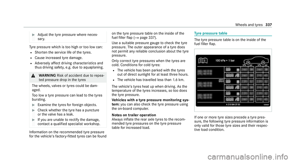
the tyre pressure table on the inside of the
fuel filler flap (/ page 337).
Use a suitable pressure gauge tocheck the tyre
pressure. The outer appearance of a tyre does
not permit any reliable conclusion about the tyre
pressure.
Only cor rect tyre pressures when the tyres are
cold. Conditions for cold tyres:
R The vehicle has been par ked with the tyres
out of direct sunlight for at least thre e hours.
R The vehicle has tr avelled less than 1.6 km.
The vehicle's tyres heat up when driving. As the
te mp erature of the tyres increases, so too does
th e tyre pressure.
Ve hicles with a tyre pressure monitoring sys‐
te m: you can also check the tyre pressure using
th e on-board computer.
Note s on trailer operation
Alw ays inflate there ar axle tyres tothere com‐
mended tyre pressures on the tyre pressure
ta ble for increased load. Ty
re pressure table The tyre pressure
table is on the inside of the
fuel filler flap. If one or more tyre sizes precede a tyre pres‐
sure,
thefo llowing tyre pressure information is
only valid forth ose tyre sizes and their respec‐
tive load condition. Wheels and tyres
337
Page 342 of 481

ing condition (/
page 337). Observethe
no tes on tyre temp erature (/ page 336).
% The values displa yed in the on-board com‐
puter may deviate from those of the tyre
pressure gauge as they referto sea le vel.At
high ele vations, the tyre pressure values
indicated bya pressure gauge are higher
th an those shown bythe on-board computer.
In this case, do not reduce the tyre pressure.
Re starting the ty repressure moni toring sys‐
tem
Re quirements:
R The recommended tyre pressure is cor rectly
set forth ere spective operating status on all
of the wheels (/ page 336).
Re start the tyre pressure monitoring sy stem in
th efo llowing situations:
R The tyre pressure has changed.
R The wheels or tyres ha vebeen changed or
newly fitted. On-boa
rdcompu ter:
4 Service 5
Tyres #
Swipe down wards on Touch Control on the
left-hand side of thesteering wheel.
The Use current tyre pressures as new refer-
ence values? message is shown in the multi‐
function displa y. #
Torestart, press Touch Control on the left-
hand side of thesteering wheel.
The Tyre press. monitor restarted message is
shown in the multifunction displa y.
Cur rent wa rning messages are dele ted and
th eye llow h warning lamp goes out.
Af teryo u ha vebeen driving for a few
minutes, the sy stem checks whe ther the cur‐
re nt tyre pressures are wi thin the specified
ra nge. The cur rent tyre pressures are then
accep ted as refere nce values and monitored.
Be sure toalso pay attention tothefo llowing
re lated topic:
R Notes on tyre pressure (/ page 336) Ty
re pressure loss warning sy stem Fu
nction of the ty repressure loss warning
sy stem
The tyre pressure loss warning sy stem warnsthe
driver bymeans of display messa ges when there
is a se vere tyre pressu reloss.
Sy stem limits
The sy stem may be impaired or may not function
particular lyin thefo llowing situations:
R incor rectly set tyre pressure
R sudden pressure loss caused, forex ample,
by afo re ign object penetrating the tyre
R steady pressure loss in se veral tyres
The sy stem has a restricted or delay ed function
particularly in thefo llowing situations:
R poor ground cond itions, e.g. snow or gr avel
R driving with snow chains
R when adopting a very sporty driving style
with high cornering speeds or sudden accel‐
eration
R driving with a very heavy or lar getrailer Wheels and tyres
339
Page 370 of 481

All models
Ve
hicle width exclud‐
ing outside mir rors 18
90 mm
Ve hicle height 1600 mm
Wheelbase 2873 mm We
ights and loads Please obser
vethefo llowing no tesfo rth e speci‐
fi ed vehicle data:
R Items of optional equipment increase the
unladen weight and reduce the pa yload.
R Vehicle-specific weight information can be
fo und on theve hicle identification plate
(/ page 355).
Obser vetheve hicle data specified below :
optional equipment increases the unladen
we ight and reduces the pa yload. Model
Maximumroof load
All models 75kg Tr
ailer hitch Gene
ral no tes on the trailer hit ch Modifications
tothe engine cooling sy stem may
be necessar y,depending on theve hicle model.
The retrofitting of a trailer hitch is only pe rmissi‐
ble if a towing capacity is specified in your vehi‐
cle documents.
Fu rther information can be obtained at a quali‐
fi ed specialist workshop. Mounting dimensions
1
Fastening points
2 Overhang dimension
3 Rear axle centre line Te
ch nical da ta367
Page 371 of 481

The
overhang dimension and fastening points
are valid for a trailer hitch ins talled at thefa c‐
to ry.
Overhang dimension Model
2 2Over‐
hang dimen‐ sion
All models 1080 mm To
wing capacity The
tongue weight is not included in theto wing
capacity.
Missing values werenot available at the time of
going topress.
To wing capacit y,braked (at a minimum start-
off gradeability of 12%) Model
Towing capacit y,
braked
GLC 200
GLC 200 4MATIC 2000kg Model
Towing capacit y,
braked
GLC 200 d2 200kg
GLC 200 d 4MATIC
GLC 300 4MATIC 24
00 kg
All other models 2500kg To
wing capacit y,unbraked Model
Towing capacit y,
unbraked
All models7 50kg Maximum
tongue weight and load capacity *
NO
TEDama gecaused bythe trailer
coming loose If
th eto ngue weight used is too lo w,the
trailer may come loose. #
The tongue weight must not be below
50 kg. #
Use a tongue weight that is as close as
possible tothe maximum permissible
to ngue weight. *
NO
TEDama gecaused bythe bicycle
ra ck coming loose When using a bicycle
rack , bo th th e maximal
to ngue weight and the maximal load capacity
should be obser ved. #
Do not exceed the permissible load
capacity. Obser
vethe additional no tes on load capacity
(/ page 245).
Missing values werenot available at the time of
going topress. 368
Tech nical da ta
Page 372 of 481
To
ngue weight Model
Maximum
to ngue
we ight
GLC 200
GLC 200 4MATIC 80kg
GLC 200 d8 8kg
GLC 200 d 4MATIC
GLC 300 4MATIC 96
kg
All other models 100kg Load capacity
Model
Maximum
load
All models Pe
rm issible rear axle load (trailer operation) Missing
values werenot available at the time of
going topress. Model
Axle load
GLC 200
GLC 200 d1 405kg
GLC 200 4MATIC 1395 kg
GLC 200 d 4MATIC 1415 kg
GLC 220 d 4MATIC 1420 kg
GLC 300 4MATIC 1400 kg
GLC 300 d 4MATIC 1425 kg
GLC 400 d 4MATIC 1440 kg Te
ch nical da ta369
Page 379 of 481
Lights
Display messages
Possible causes/consequences and M MSolutions
: Left dipped beam (examp le) *T
he cor responding light source is defective. #
Drive on carefully. #
Consult a qualified specialist workshop immediatel y.
% LED light sources: the display message forth e cor responding light appears only when allthe light-emitting
diodes in the light are faulty.
: Malfunction See Owner's
Manual *T
heexterior lighting is malfunctioning. #
Consult a qualified specialist workshop.
* Ve hicles with a trailer hitch: a fuse may haveblown. #
Stop theve hicle in accordance with the tra ffic conditions. #
Check the fuses and replace them if necessary (/ page 331).
:
Automatic driving lights
inoperative *T
he light sensor for auto matic driving lights is malfunctioning. #
Consult a qualified specialist workshop. 376
Displaymessa ges and warning/indicator lamps
Page 384 of 481

Ve
hicle Display messages
Possible causes/consequences and M MSolutions
d Vehicle is operational
Switch off ignition before
exiting *Y
ou are leaving theve hicle in a ready-to-drive state. #
When you lea vetheve hicle, switch off the ignition, secure theve hicle against rolling away and take theke y with
yo u. #
Ifyo u do not lea vetheve hicle, switch off the electrical consumers, e.g. the seat heating. Otherwise, the12 ‑V
battery may discharge and starting the engine may be possible only with the help of a second battery (jump
st art).
ï
Operation only possible in
transmission position P *
The ball neck will not swivel because transmission position h,kor neut rali is selec ted. #
Depress the brake pedal. #
Enga gepark position j.
ï
Trailer coupling in motion *T
he ball neck is retracting/extending.
Do not attem pttospeed up, slow down or initiate the swivel mo vement using your hand, foot or other aids. During
th e swivel mo vement, do not couple a trailer.
When the ball neck has reached an operational position, the display message will disappear. Display messages and
warning/indicator lamps 381
Page 385 of 481

Display messages
Possible causes/consequences and M MSolutions
ï Check trailer hitch lock *T
he trailer hitch is not operational during a journey with a trailer. &
WARNING Risk of an accident if the ball neck is not loc ked
The trailer may become de tach ed. #
Stop theve hicle immediately in accordance with the traf fic conditions. Do not continue driving. #
Uncouple the trailer and secure it against rolling away. #
Initiate a new swivel mo vement and do not re-couple the trailer until thewa rning/indicator lamp goes out. #
Initiate a new swivel mo vement (/ page240). #
When the display message disappears, couple up the trailer and drive on.
If th e display message does not disappear, the trailer hitch is malfunctioning and the ball neck is not loc ked. #
Do not couple up the trailer. Drive on without the trailer. No tethere duced ground clearance due tothe
unlo cked ball nec k. #
Consult a qualified specialist workshop.
*T he trailer hitch will not be operational when theve hicle is stationar y. #
Uncouple the coupled trailer and secure it against rolling away. #
Ifth e ball neck has been retracted: initiatea new swivel mo vement (/ page240).
The ball neck will engage vertically in the loc ked position and then engage beneath the bumper. 382
Display messages and warning/indicator lamps