2021 CHRYSLER 300 ECO mode
[x] Cancel search: ECO modePage 142 of 268
140 SAFETY
(Continued)
Partial Off
This mode may be useful if the vehicle becomes
st
uck. This mode may modify TCS and ESC
thresholds for activation, which allows for more
wheel spin than normally allowed.
To enter the “Partial Off” mode, momentarily push
th
e ESC OFF button and the ESC OFF Indicator
Light will illuminate. To turn the ESC on again,
momentarily push the ESC OFF button and the ESC
OFF Indicator Light will turn off.
NOTE:
For vehicles with multiple partial ESC modes,
the push and release of the button will toggle
the ESC modes. Multiple attempts may be
required to return to "ESC On" mode.
Trailer Sway Control (TSC) is disabled when the
ESC system is in the “Partial Off” mode.
If Equipped — "ESC Sport" and "ESC Track" are
ESC “Partial Off” mode(s).
Full Off – If Equipped
This mode is intended for off-highway or off-road
u s
e only and should not be used on any public
roadways. In this mode, TCS and ESC features are
turned off. To enter the “Full Off” mode, push and
hold the ESC OFF button for five seconds while the
vehicle is stopped with the engine running. After
five seconds, a chime will sound, the ESC OFF
Indicator Light will illuminate, and the “ESC OFF”
message will display in the instrument cluster. To
turn ESC on again, momentarily push the ESC OFF
button.
ESC Activation/Malfunction Indicator Light
And ESC OFF Indicator Light
The ESC Activation/Malfunction Indicator
Light in the instrument cluster will come
o n
when the ignition is placed in the ON
position. It should go out with the engine
running. If the ESC Activation/Malfunction
Indicator Light comes on continuously with the
engine running, a malfunction has been detected
in the ESC system. If this light remains on after
several ignition cycles, and the vehicle has been
driven several miles (kilometers) at speeds greater
WARNING!
When in “Partial Off” mode, the TCS functionality
of ESC (except for the limited slip feature
described in the TCS section) has been disabled
and the ESC OFF Indicator Light will be
illuminated. When in “Partial Off” mode, the
engine power reduction feature of TCS is
disabled, and the enhanced vehicle stability
offered by the ESC system is reduced.
WARNING!
In the ESC “Full Off” mode, the engine torque
reduction and stability features are disabled.
Therefore, enhanced vehicle stability offered
by the ESC system is unavailable. In an emer -
gency evasive maneuver, the ESC system will
n ot
engage to assist in maintaining stability.
ESC “Full Off” mode is intended for
off-highway or off-road use only.
With the ESC switched off, the enhanced
vehicle stability offered by ESC is unavailable.
In an emergency evasive maneuver, the ESC
system will not engage to assist in maintaining
stability. ESC “Full Off” mode is only intended
for off-highway or off-road use.
The Electronic Stability Control (ESC) cannot
prevent the natural laws of physics from
acting on the vehicle, nor can it increase the
traction afforded by prevailing road condi -
tions. ESC cannot prevent all accidents,
i n
cluding those resulting from excessive
speed in turns, driving on very slippery
surfaces, or hydroplaning. ESC also cannot
prevent collisions.
WARNING!
Page 143 of 268
SAFETY 141
than 30 mph (48 km/h), see an authorized dealer
as
soon as possible to have the problem
diagnosed and corrected.
The ESC Activation/Malfunction Indicator Light
s t
arts to flash as soon as the tires lose traction and
the ESC system becomes active. The ESC
Activation/Malfunction Indicator Light also flashes
when TCS is active. If the ESC Activation/
Malfunction Indicator Light begins to flash during
acceleration, ease up on the accelerator and apply
as little throttle as possible. Be sure to adapt your
speed and driving to the prevailing road conditions.
The ESC OFF Indicator Light indicates the
customer has elected to have the
El
ectronic Stability Control (ESC) in a
reduced mode.
NOTE:
The ESC Activation/Malfunction Indicator Light
and the ESC OFF Indicator Light come on
momentarily each time the ignition is placed in
the ON position.
Each time the ignition is placed in the ON posi -
tion, the ESC system will be on even if it was
t u
rned off previously.
The ESC system will make buzzing or clicking
sounds when it is active. This is normal; the
sounds will stop when ESC becomes inactive
following the maneuver that caused the ESC
activation.
Hill Start Assist (HSA)
HSA is designed to mitigate roll back from a
complete stop while on an incline. If the driver
releases the brake while stopped on an incline,
HSA will continue to hold the brake pressure for a
short period. If the driver does not apply the
throttle before this time expires, the system will
release brake pressure and the vehicle will roll
down the hill as normal.
The following conditions must be met in order for
HS A
to activate:
The feature must be enabled.
The vehicle must be stopped.
The parking brake must be off.
The driver door must be closed.
The vehicle must be on a sufficient grade.
The gear selection must match vehicle uphill
direction (i.e., vehicle facing uphill is in forward
gear; vehicle backing uphill is in REVERSE gear).
HSA will work in REVERSE gear and all forward
gears. The system will not activate if the trans -
mission is in PARK or NEUTRAL. For vehicles
e q
uipped with a manual transmission, if the
clutch is pressed, HSA will remain active.
Disabling And Enabling HSA
This feature can be turned on or turned off. To
change the current setting using Uconnect
Settings, see
Ú page 122 for further information.
WARNING!
There may be situations where the Hill Start
Assist (HSA) will not activate and slight rolling
may occur, such as on minor hills or with a
loaded vehicle, or while pulling a trailer. HSA is
not a substitute for active driving involvement. It
is always the driver’s responsibility to be
attentive to distance to other vehicles, people,
and objects, and most importantly brake
operation to ensure safe operation of the vehicle
under all road conditions. Your complete
attention is always required while driving to
maintain safe control of your vehicle. Failure to
follow these warnings can result in a collision or
serious personal injury.
6
Page 148 of 268

146 SAFETY
Blind Spot Modes
Blind Spot has three selectable modes of
operation that are available in the Uconnect
system.
Blind Spot Alert Lights Only
When operating in Blind Spot Alert mode, the BSM
sy
stem will provide a visual alert in the appropriate
side view mirror based on a detected object.
However, when the system is operating in Rear
Cross Path (RCP) mode, the system will respond
with both visual and audible alerts when a
detected object is present. Whenever an audible
alert is requested, the radio is muted.
Blind Spot Alert Lights/Chime
When operating in Blind Spot Alert Lights/Chime
m od
e, the BSM system will provide a visual alert in
the appropriate side view mirror based on a
detected object. If the turn signal is then activated,
and it corresponds to an alert present on that side
of the vehicle, an audible chime will also be
sounded. Whenever a turn signal and detected
object are present on the same side at the same
time, both the visual and audible alerts will be
issued. In addition to the audible alert the radio (if
on) will also be muted.
NOTE:
Whenever an audible alert is requested by the
B S
M system, the radio is also muted. When the system is in RCP, the system shall
r
e
spond with both visual and audible alerts when a
detected object is present. Whenever an audible
alert is requested, the radio is also muted. Turn/
hazard signal status is ignored; the RCP state
always requests the chime.
Blind Spot Alert Off
When the BSM system is turned off there will be no
v i
sual or audible alerts from either the BSM or RCP
systems.
NOTE:
The BSM system will store the current operating
m od
e when the vehicle is shut off. Each time the
vehicle is started the previously stored mode will
be recalled and used.
FORWARD COLLISION WARNING (FCW)
W
ITH MITIGATION OPERATION —
I
F EQUIPPED
FCW with Mitigation provides the driver with
audible warnings, visual warnings (within the
instrument cluster display), and may apply a brake
jerk to warn the driver when it detects a potential
frontal collision. The warnings and limited braking
are intended to provide the driver with enough time
to react, avoid or mitigate the potential collision.
NOTE:
FCW monitors the information from the forward
l ook
ing sensors, as well as the Electronic Stability
Control (ESC) system, to calculate the probability of
a forward collision. When the system determines
that a forward collision is probable, the driver will
be provided with audible and visual warnings and
may provide a brake jerk warning. If the driver does
not take action based upon these progressive
warnings, then the system will provide a limited
level of active braking to help slow the vehicle and
mitigate the potential forward collision. If the driver
reacts to the warnings by braking and the system
determines that the driver intends to avoid the
collision by braking but has not applied sufficient
brake force, the system will compensate and
provide additional brake force as required. If a
Forward Collision Warning with Mitigation event
begins at a speed below 20 mph (32 km/h), the
s y
stem may provide the maximum or partial
braking to mitigate the potential forward collision.
If the Forward Collision Warning with Mitigation
event stops the vehicle completely, the system will
hold the vehicle at standstill for two seconds and
then release the brakes.
Page 153 of 268

SAFETY 151
3. After driving the vehicle for up to 20 minutes
ab
ove 15 mph (24 km/h), the TPMS Warning
Li g
ht will flash on and off for 75 seconds and
then remain on solid. In addition, the
instrument cluster will display a “Service Tire
Pressure System” message for five seconds
and then display dashes (- -) in place of the
pressure value.
4. F or each subsequent ignition key cycle, a
c
hime will sound, the TPMS Warning Light will
flash on and off for 75 seconds and then
remain on solid, and the instrument cluster will
display a “Service Tire Pressure System”
message for five seconds and then display
dashes (- -) in place of the pressure value.
5. O nce you repair or replace the original road tire
a
nd reinstall it on the vehicle in place of the
compact spare or non-matching full size, the
TPMS will update automatically. In addition, the
TPMS Warning Light will turn off and the graphic
in the instrument cluster will display a new
pressure value instead of dashes (- -), as long as
no tire pressure is below the low-pressure
warning limit in any of the four active road tires.
The vehicle may need to be driven for up to
20 minutes above 15 mph (24 km/h) in order
f o
r the TPMS to receive this information.
TPMS Deactivation — If Equipped
The Tire Pressure Monitoring System (TPMS) can
be deactivated if replacing all four wheel and tire
assemblies (road tires) with wheel and tire
assemblies that do not have TPMS sensors, such
as when installing winter wheel and tire
assemblies on your vehicle.
To deactivate the TPMS, first replace all four wheel
a n
d tire assemblies (road tires) with tires not
equipped with Tire Pressure Monitoring System
(TPMS) sensors. Then, drive the vehicle for
20 minutes above 15 mph (24 km/h). The TPMS
wi
ll chime, the TPMS Warning Light will flash on
and off for 75 seconds and then remain on. The
instrument cluster will display the “Service Tire
Pressure System” message and then display
dashes (--) in place of the pressure values.
Beginning with the next ignition cycle, the TPMS
wi
ll no longer chime or display the “Service Tire
Pressure System” message in the instrument
cluster but dashes (--) will remain in place of the
pressure values. To reactivate the TPMS, replace all four wheel and
t
i
re assemblies (road tires) with tires equipped with
TPMS sensors. Then, drive the vehicle for up to
20 minutes above 15 mph (24 km/h). The TPMS
w i
ll chime, the TPMS Warning Light will flash on
and off for 75 seconds and then turn off. The
instrument cluster will display the “Service Tire
Pressure System” message and then display
pressure values in place of the dashes. On the next
ignition cycle the "Service Tire Pressure System"
message will no longer be displayed as long as no
system fault exists.
OCCUPANT RESTRAINT SYSTEMS
Some of the most important safety features in your
vehicle are the restraint systems:
OCCUPANT RESTRAINT SYSTEMS
F
EATURES
Seat Belt Systems
Supplemental Restraint Systems (SRS) Air Bags
Child Restraints
Some of the safety features described in this
s e
ction may be standard equipment on some
models, or may be optional equipment on others. If
you are not sure, ask an authorized dealer.
6
Page 176 of 268
174 SAFETY
Installing A Child Restraint With A
Switchable Automatic Locking Retractor
(ALR):
Child restraint systems are designed to be secured
in vehicle seats by lap belts or the lap belt portion
of a lap/shoulder belt.
1. P
lace the child seat in the center of the
s
eating position. If the second row seat can
be reclined, you may recline the seat and/or
raise the head restraint (if adjustable) to get a
better fit. If the rear seat can be moved
forward and rearward in the vehicle, you may
wish to move it to its rear-most position to
make room for the child seat. You may also
move the front seat forward to allow more
room for the child seat.
2. P ull enough of the seat belt webbing from the
r
etractor to pass it through the belt path of the
child restraint. Do not twist the belt webbing in
the belt path.
3. Slide the latch plate into the buckle until you h
ear a “click.” 4. P
ull on the webbing to make the lap portion
t
ight against the child seat.
5. To lock the seat belt, pull down on the shoulder p
art of the belt until you have pulled all the
seat belt webbing out of the retractor. Then,
allow the webbing to retract back into the
retractor. As the webbing retracts, you will hear
a clicking sound. This means the seat belt is
now in the Automatic Locking mode.
6. T ry to pull the webbing out of the retractor. If it
i
s locked, you should not be able to pull out any
webbing. If the retractor is not
locked, repeat
step 5.
Frequently Asked Questions About Installing Child Restraints With Seat Belts
What is the weight limit (child’s weight + weight of the child
restraint) for using the Tether Anchor with the seat belt to
attach a forward facing child restraint? Weight limit of the Child
Re
straint Always use the tether anchor when using the seat belt to
i
n
stall a forward facing child restraint, up to the recommended
weight limit of the child restraint.
Can the rear-facing child restraint touch the back of the front
p a
ssenger seat? YesContact between the front passenger seat and the child
r
e
straint is allowed, if the child restraint manufacturer also
allows contact.
Can the rear head restraints be removed? No
Can the buckle stalk be twisted to tighten the seat belt against
th
e belt path of the child restraint? NoDo not twist the buckle stalk in a seating position with an ALR
re
tractor.
WARNING!
Improper installation or failure to properly
secure a child restraint can lead to failure of
the restraint. The child could be badly injured
or killed.
Follow the child restraint manufacturer’s
directions exactly when installing an infant or
child restraint.
Page 179 of 268
SAFETY 177
(Continued)
(Continued)
Defroster
Check operation by selecting the defrost mode and
place the blower control on high speed. You should
be able to feel the air directed against the
windshield. See an authorized dealer for service if
your defroster is inoperable.
Floor Mat Safety Information
Always use floor mats designed to fit your vehicle.
Only use a floor mat that does not interfere with the
operation of the accelerator, brake or clutch
pedals. Only use a floor mat that is securely
attached using the floor mat fasteners so it cannot
slip out of position and interfere with the
accelerator, brake or clutch pedals or impair safe
operation of your vehicle in other ways.
PERIODIC SAFETY CHECKS YOU SHOULD
M
AKE OUTSIDE THE VEHICLE
Tires
Examine tires for excessive tread wear and uneven
wear patterns. Check for stones, nails, glass, or
other objects lodged in the tread or sidewall.
Inspect the tread for cuts and cracks. Inspect
sidewalls for cuts, cracks, and bulges. Check the
WARNING!
An improperly attached, damaged, folded, or
stacked floor mat, or damaged floor mat fasteners
may cause your floor mat to interfere with the
accelerator, brake, or clutch pedals and cause a
loss of vehicle control. To prevent SERIOUS
INJURY or DEATH:
ALWAYS securely attach your floor mat using
the floor mat fasteners. DO NOT install your
f l
oor mat upside down or turn your floor mat
over. Lightly pull to confirm mat is secured
using the floor mat fasteners on a regular basis.
ALWAYS REMOVE THE EXISTING FLOOR MAT
FROM THE VEHICLE before installing any
other floor mat. NEVER install or stack an addi -
tional floor mat on top of an existing floor mat.
ONLY install floor mats designed to fit your
vehicle. NEVER install a floor mat that cannot
be properly attached and secured to your
vehicle. If a floor mat needs to be replaced, only
use a FCA approved floor mat for the specific
make, model, and year of your vehicle.
ONLY use the driver’s side floor mat on the
driver’s side floor area. To check for interfer -
ence, with the vehicle properly parked with the
e n
gine off, fully depress the accelerator, the
brake, and the clutch pedal (if present) to check
for interference. If your floor mat interferes with
the operation of any pedal, or is not secure to
the floor, remove the floor mat from the vehicle
and place the floor mat in your trunk.
ONLY use the passenger’s side floor mat on the
passenger’s side floor area.
ALWAYS make sure objects cannot fall or slide
into the driver’s side floor area when the vehicle
is moving. Objects can become trapped under
accelerator, brake, or clutch pedals and could
cause a loss of vehicle control.
WARNING!
NEVER place any objects under the floor mat
(e.g., towels, keys, etc.). These objects could
change the position of the floor mat and may
cause interference with the accelerator, brake,
or clutch pedals.
If the vehicle carpet has been removed and
re-installed, always properly attach carpet to
the floor and check the floor mat fasteners are
secure to the vehicle carpet. Fully depress each
pedal to check for interference with the acceler -
ator, brake, or clutch pedals then re-install the
f l
oor mats.
It is recommended to only use mild soap and
water to clean your floor mats. After cleaning,
always check your floor mat has been properly
installed and is secured to your vehicle using
the floor mat fasteners by lightly pulling mat.
WARNING!
6
Page 194 of 268
192 IN CASE OF EMERGENCY
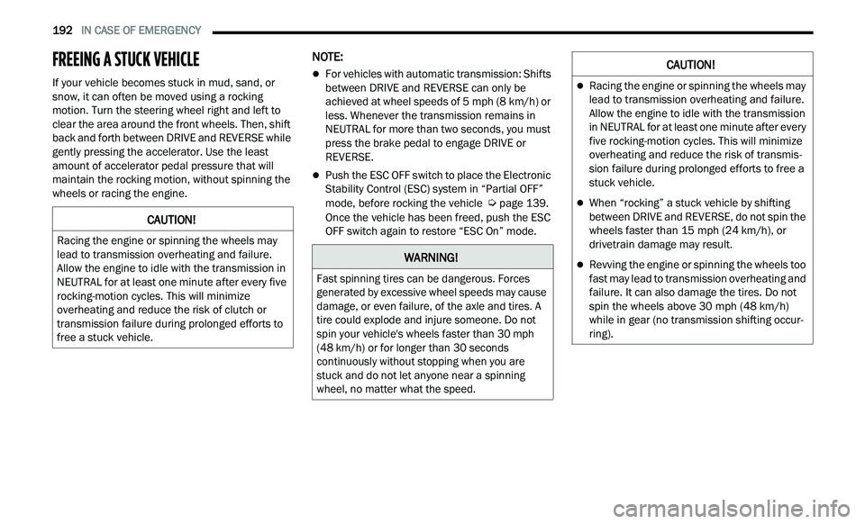
FREEING A STUCK VEHICLE
If your vehicle becomes stuck in mud, sand, or
snow, it can often be moved using a rocking
motion. Turn the steering wheel right and left to
clear the area around the front wheels. Then, shift
back and forth between DRIVE and REVERSE while
gently pressing the accelerator. Use the least
amount of accelerator pedal pressure that will
maintain the rocking motion, without spinning the
wheels or racing the engine.
NOTE:
For vehicles with automatic transmission: Shifts
between DRIVE and REVERSE can only be
achieved at wheel speeds of 5
mph (8 km/h) or
le
ss. Whenever the transmission remains in
NEUTRAL for more than two seconds, you must
press the brake pedal to engage DRIVE or
REVERSE.
Push the ESC OFF switch to place the Electronic
Stability Control (ESC) system in “Partial OFF”
mode, before rocking the vehicle
Ú page 139.
Once the vehicle has been freed, push the ESC
O F
F switch again to restore “ESC On” mode.CAUTION!
Racing the engine or spinning the wheels may
lead to transmission overheating and failure.
Allow the engine to idle with the transmission in
NEUTRAL for at least one minute after every five
rocking-motion cycles. This will minimize
overheating and reduce the risk of clutch or
transmission failure during prolonged efforts to
free a stuck vehicle.
WARNING!
Fast spinning tires can be dangerous. Forces
generated by excessive wheel speeds may cause
damage, or even failure, of the axle and tires. A
tire could explode and injure someone. Do not
spin your vehicle's wheels faster than 30 mph
(4
8 km/h) or for longer than 30 seconds
c o
ntinuously without stopping when you are
stuck and do not let anyone near a spinning
wheel, no matter what the speed.
CAUTION!
Racing the engine or spinning the wheels may
lead to transmission overheating and failure.
Allow the engine to idle with the transmission
in NEUTRAL for at least one minute after every
five rocking-motion cycles. This will minimize
overheating and reduce the risk of transmis -
sion failure during prolonged efforts to free a
s t
uck vehicle.
When “rocking” a stuck vehicle by shifting
between DRIVE and REVERSE, do not spin the
wheels faster than 15 mph (24 km/h), or
dr
ivetrain damage may result.
Revving the engine or spinning the wheels too
fast may lead to transmission overheating and
failure. It can also damage the tires. Do not
spin the wheels above 30 mph (48 km/h)
w h
ile in gear (no transmission shifting occur -
ring).
Page 195 of 268
IN CASE OF EMERGENCY 193
TOWING A DISABLED VEHICLE
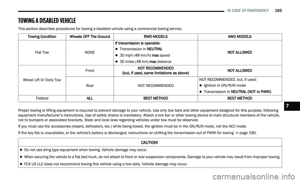
This section describes procedures for towing a disabled vehicle using a commercial towing service.
Proper towing or lifting equipment is required to prevent damage to your vehicle. Use only tow bars and other equipment designed for this purpose, following
eq
uipment manufacturer’s instructions. Use of safety chains is mandatory. Attach a tow bar or other towing device to main structural members of the vehicle,
not to bumpers or associated brackets. State and local laws regarding vehicles under tow must be observed.
If you must use the accessories (wipers, defrosters, etc.) while being towed, the ignition must be in the ON/RUN mode, not the ACC mode.
If the key fob is unavailable, or the vehicle's battery is discharged, instructions on shifting the transmission out of PARK for towing
Ú page 190.
Towing Condition
Wheels OFF The Ground RWD MODELS AWD MODELS
Flat Tow NONEIf transmission is operable:
Transmission in NEUTRAL
30 mph (48 km/h) max speed
30 miles (48 km) max distance NOT ALLOWED
Wheel Lift Or Dolly Tow Front
NOT RECOMMENDED
(b
ut, if used, same limitations as above) NOT ALLOWED
Rear NOT RECOMMENDED NOT RECOMMENDED, but, if used:
Ignition in ON/RUN mode
Transmission in
NEUTRAL (NOT in PARK)
Flatbed ALL BEST METHOD BEST METHOD
CAUTION!
Do not use sling type equipment when towing. Vehicle damage may occur.
When securing the vehicle to a flat bed truck, do not attach to front or rear suspension components. Damage to your vehicle may result from improper towing.
FCA US LLC does not recommend towing this vehicle using a tow dolly. Vehicle damage may occur.
7