2021 CHRYSLER 300 air condition
[x] Cancel search: air conditionPage 7 of 268

5
SAFETY
SAFETY FEATURES .............................................. 137
Anti-Lock Brake System (ABS) .. ................... 137
Electronic Brake Control (EBC) System . . ..... 138
AUXILIARY DRIVING SYSTEMS . . ........................ 142
Blind Spot Monitoring (BSM) —
If Equipped. .
................................................... 142
Forward Collision Warning (FCW) With
Mitigation Operation — If Equipped. .
............ 146
Tire Pressure Monitoring System (TPMS) . . .. 148
OCCUPANT RESTRAINT SYSTEMS . . .................. 151
Occupant Restraint Systems Features .. ..... 151
Important Safety Precautions. . ..................... 152
Seat Belt Systems . . ...................................... 152
Supplemental Restraint Systems (SRS) . . .... 158
Child Restraints . . ........................................... 166
SAFETY TIPS . . ....................................................... 176
Transporting Passengers .. ............................ 176
Transporting Pets . . ........................................ 176
Safety Checks You Should Make Inside
The Vehicle . .
................................................. 176
Periodic Safety Checks You Should Make
Outside The Vehicle . .
.................................... 177
Exhaust Gas . . ................................................ 178
Carbon Monoxide Warnings . . ....................... 178
IN CASE OF EMERGENCY
HAZARD WARNING FLASHERS......................... 179
ASSIST AND SOS MIRROR — IF EQUIPPED .. ... 179
JACKING AND TIRE CHANGING .. ....................... 182
Preparations For Jacking .. ........................... 182
Jack Location/Spare Tire Stowage . . ............ 183
Jacking And Changing A Tire . . ..................... 184
JUMP STARTING . . ............................................... 186
Preparations For Jump Start .. ...................... 187
Jump Starting Procedure . . ............................ 188
REFUELING IN AN EMERGENCY –
IF EQUIPPED . .
..................................................... 189
IF YOUR ENGINE OVERHEATS .. ........................ 190
MANUAL PARK RELEASE .. ................................ 190
FREEING A STUCK VEHICLE .. ............................ 192
TOWING A DISABLED VEHICLE .. ....................... 193
All Wheel Drive (AWD) Models .. .................... 194
Rear Wheel Drive (RWD) Models . . ............... 194
ENHANCED ACCIDENT RESPONSE SYSTEM
(EARS) . ................................................................. 194
E
VENT DATA RECORDER (EDR) .. ...................... 194
SERVICING AND MAINTENANCE
SCHEDULED SERVICING ................................... 195
Maintenance Plan .. ....................................... 196
ENGINE COMPARTMENT . . .................................. 199
3.6L Engine .. ................................................ 199
5.7L Engine . . ................................................ 200
Checking Oil Level . . ....................................... 201 Adding Washer Fluid .
.
................................... 201
Maintenance-Free Battery . . ......................... 201
Pressure Washing . . ....................................... 202
VEHICLE MAINTENANCE . . .................................. 202
Engine Oil ...................................................... 202
E ngine Oil Filter . . ........................................... 203
Engine Air Cleaner Filter . . ............................. 203
Air Conditioner Maintenance. . ...................... 204
Accessory Drive Belt Inspection . . ................. 205
Body Lubrication . . ......................................... 206
Windshield Wiper Blades. . ............................ 206
Exhaust System . . ........................................... 208
Cooling System . . ........................................... 209
Brake System . . ............................................. 212
Automatic Transmission . . ............................ 212
All Wheel Drive (AWD) — If Equipped . . ........ 213
Rear Axle. ....................................................... 213
F uses. ............................................................. 214
B ulb Replacement . . ...................................... 221
TIRES . .................................................................... 225
T ire Safety Information .. ............................... 225
Tires — General Information . . ...................... 232
Tire Types. ...................................................... 235
S pare Tires — If Equipped. . ........................... 236
Wheel And Wheel Trim Care. . ....................... 238
Snow Traction Devices. . ................................ 239
Tire Rotation Recommendations . . .............. 240
Page 49 of 268
GETTING TO KNOW YOUR VEHICLE 47
The Rain Sensing system has protection features
for the wiper blades and arms, and will not operate
under the following conditions:
Low Ambient Temperature — When the ignition
is first placed in the ON position, the Rain
Sensing system will not operate until the wiper
switch is moved, vehicle speed is greater than
3 mph (5 km/h), or the outside temperature is
gr
eater than 32°F (0°C).
Transmission In NEUTRAL Position — When the
ignition is ON, and the automatic transmission
is in the NEUTRAL position, the Rain Sensing
system will not operate until the wiper switch is
moved, vehicle speed is greater than 3 mph
(5
km/h), or the gear selector is moved out of
t h
e NEUTRAL position.
Remote Start Mode Inhibit — On vehicles
equipped with a Remote Start system, Rain
Sensing wipers are not operational when the
vehicle is in Remote Start mode.
CLIMATE CONTROLS
The Climate Control system allows you to regulate
the temperature, air flow, and direction of air
circulating throughout the vehicle. The controls are
located on the touchscreen (if equipped) and on
the instrument panel below the radio.
AUTOMATIC CLIMATE CONTROL
D
ESCRIPTIONS AND FUNCTIONS
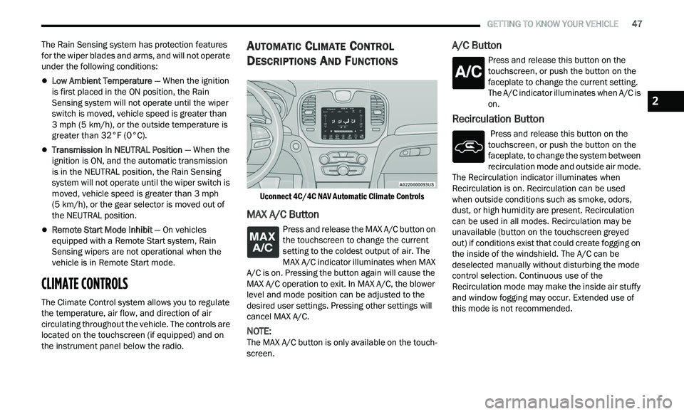
Uconnect 4C/4C NAV Automatic Climate Controls
MAX A/C Button
Press and release the MAX A/C button on
the touchscreen to change the current
s e
tting to the coldest output of air. The
MAX A/C indicator illuminates when MAX
A/C is on. Pressing the button again will cause the
MAX A/C operation to exit. In MAX A/C, the blower
level and mode position can be adjusted to the
desired user settings. Pressing other settings will
cancel MAX A/C.
NOTE:
The MAX A/C button is only available on the touch -
screen.
A/C Button
Press and release this button on the
touchscreen, or push the button on the
f a
ceplate to change the current setting.
The A/C indicator illuminates when A/C is
on.
Recirculation Button
Press and release this button on the
touchscreen, or push the button on the
f a
ceplate, to change the system between
recirculation mode and outside air mode.
The Recirculation indicator illuminates when
Recirculation is on. Recirculation can be used
when outside conditions such as smoke, odors,
dust, or high humidity are present. Recirculation
can be used in all modes. Recirculation may be
unavailable (button on the touchscreen greyed
out) if conditions exist that could create fogging on
the inside of the windshield. The A/C can be
deselected manually without disturbing the mode
control selection. Continuous use of the
Recirculation mode may make the inside air stuffy
and window fogging may occur. Extended use of
this mode is not recommended.
2
Page 51 of 268
GETTING TO KNOW YOUR VEHICLE 49
The speeds can be selected using either the
blower control knob on the faceplate or the
buttons on the touchscreen.
Faceplate
The blower speed increases as you turn the blower
c
on
trol knob clockwise from the lowest blower
setting. The blower speed decreases as you turn
the blower control knob counterclockwise.
Touchscreen
Use the small blower icon to reduce the blower
s e
tting and the large blower icon to increase the
blower setting. Blower can also be selected by
pressing the blower bar area between the icons.
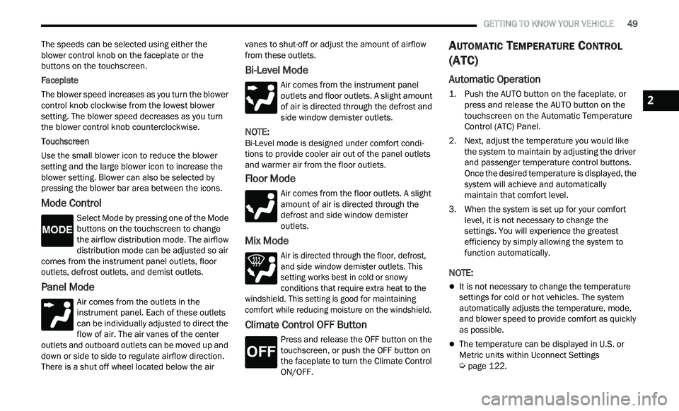
Mode Control
Select Mode by pressing one of the Mode
buttons on the touchscreen to change
t h
e airflow distribution mode. The airflow
distribution mode can be adjusted so air
comes from the instrument panel outlets, floor
outlets, defrost outlets, and demist outlets.
Panel Mode
Air comes from the outlets in the
instrument panel. Each of these outlets
c a
n be individually adjusted to direct the
flow of air. The air vanes of the center
outlets and outboard outlets can be moved up and
down or side to side to regulate airflow direction.
There is a shut off wheel located below the air vanes to shut-off or adjust the amount of airflow
from these outlets.
Bi-Level Mode
Air comes from the instrument panel
outlets and floor outlets. A slight amount
of
air is directed through the defrost and
side window demister outlets.
NOTE:
Bi-Level mode is designed under comfort condi -
tions to provide cooler air out of the panel outlets
a n
d warmer air from the floor outlets.
Floor Mode
Air comes from the floor outlets. A slight
amount of air is directed through the
de
frost and side window demister
outlets.
Mix Mode
Air is directed through the floor, defrost,
and side window demister outlets. This
s e
tting works best in cold or snowy
conditions that require extra heat to the
windshield. This setting is good for maintaining
comfort while reducing moisture on the windshield.
Climate Control OFF Button
Press and release the OFF button on the
touchscreen, or push the OFF button on
t h
e faceplate to turn the Climate Control
ON/OFF.
AUTOMATIC TEMPERATURE CONTROL
(ATC)
Automatic Operation
1. Push the AUTO button on the faceplate, or
press and release the AUTO button on the
touchscreen on the Automatic Temperature
Control (ATC) Panel.
2. Next, adjust the temperature you would like t
he system to maintain by adjusting the driver
and passenger temperature control buttons.
Once the desired temperature is displayed, the
system will achieve and automatically
maintain that comfort level.
3. When the system is set up for your comfort l
evel, it is not necessary to change the
settings. You will experience the greatest
efficiency by simply allowing the system to
function automatically.
NOTE:
It is not necessary to change the temperature
settings for cold or hot vehicles. The system
automatically adjusts the temperature, mode,
and blower speed to provide comfort as quickly
as possible.
The temperature can be displayed in U.S. or
Metric units within Uconnect Settings
Ú page 122.
2
Page 52 of 268
50 GETTING TO KNOW YOUR VEHICLE
To provide you with maximum comfort in the
Automatic mode during cold start-ups, the blower
fan will remain on low until the engine warms up.
The blower will increase in speed and transition
into Auto mode.
Manual Operation Override
This system offers a full complement of manual
override features. The AUTO symbol in the front
ATC display will be turned off when the system is
being used in the manual mode.
CLIMATE VOICE COMMANDS
Adjust vehicle temperatures hands-free and keep
everyone comfortable while you keep moving
ahead.
Push the VR button. After the beep, say one of the
fol
lowing commands:
“Set the driver temperature to 70 degrees ”
“Set the passenger temperature to 70 degrees ”
TIP:
Voice Command for Climate may only be used to
a d
just the interior temperature of your vehicle.
Voice Command will not work to adjust the heated
seats or steering wheel if equipped.
OPERATING TIPS
NOTE:
Refer to the chart at the end of this section for
s u
ggested control settings for various weather
conditions.
Summer Operation
The engine cooling system must be protected with
a high-quality antifreeze coolant to provide proper
corrosion protection and to protect against engine
overheating. OAT coolant (conforming to
MS.90032) is recommended.
Winter Operation
To ensure the best possible heater and defroster
performance, make sure the engine cooling
system is functioning properly and the proper
amount, type, and concentration of coolant is
used. Use of the Air Recirculation mode during
Winter months is not recommended, because it
may cause window fogging.
Vacation/Storage
For information on maintaining the Climate Control
system when the vehicle is being stored for an
extended period of time, see
Ú page 242.
Window Fogging
Vehicle windows tend to fog on the inside in mild,
rainy, and/or humid weather. To clear the
windows, select Defrost or Mix mode and increase
the front blower speed. Do not use the
Recirculation mode without A/C for long periods,
as fogging may occur.
Outside Air Intake
Make sure the air intake, located directly in front of
the windshield, is free of obstructions, such as
leaves. Leaves collected in the air intake may
reduce airflow, and if they enter the air distribution
box, they could plug the water drains. In Winter
months, make sure the air intake is clear of ice,
slush, and snow.
Cabin Air Filter
The Climate Control system filters out dust and
pollen from the air. Contact an authorized dealer to
service your cabin air filter, and to have it replaced
when needed.
Page 68 of 268
66 GETTING TO KNOW YOUR INSTRUMENT PANEL
INSTRUMENT CLUSTER DESCRIPTIONS
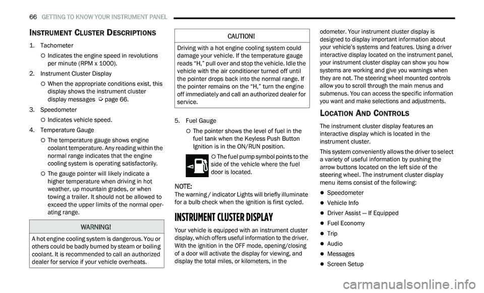
1. Tachometer
Indicates the engine speed in revolutions
per minute (RPM x 1000).
2. Instrument Cluster Display
When the appropriate conditions exist, this
display shows the instrument cluster
display messages
Ú page 66.
3. S peedometer
Indicates vehicle speed.
4. T emperature Gauge
The temperature gauge shows engine
coolant temperature. Any reading within the
normal range indicates that the engine
cooling system is operating satisfactorily.
The gauge pointer will likely indicate a
higher temperature when driving in hot
weather, up mountain grades, or when
towing a trailer. It should not be allowed to
exceed the upper limits of the normal oper
-
ating range. 5. Fuel Gauge
The pointer shows the level of fuel in the
fuel tank when the Keyless Push Button
Ignition is in the ON/RUN position.
The fuel pump symbol points to the
side of the vehicle where the fuel
d oor
is located.
NOTE:
The warning / indicator Lights will briefly illuminate
f or
a bulb check when the ignition is first cycled.
INSTRUMENT CLUSTER DISPLAY
Your vehicle is equipped with an instrument cluster
display, which offers useful information to the driver.
With the ignition in the OFF mode, opening/closing
of a door will activate the display for viewing, and
display the total miles, or kilometers, in the odometer. Your instrument cluster display is
designed to display important information about
your vehicle’s systems and features. Using a driver
interactive display located on the instrument panel,
your instrument cluster display can show you how
systems are working and give you warnings when
they are not. The steering wheel mounted controls
allow you to scroll through the main menus and
submenus. You can access the specific information
you want and make selections and adjustments.
LOCATION AND CONTROLS
The instrument cluster display features an
interactive display which is located in the
instrument cluster.
This system conveniently allows the driver to select
a
variety of useful information by pushing the
arrow buttons located on the left side of the
steering wheel. The instrument cluster display
menu items consist of the following:
Speedometer
Vehicle Info
Driver Assist — If Equipped
Fuel Economy
Trip
Audio
Messages
Screen Setup
WARNING!
A hot engine cooling system is dangerous. You or
others could be badly burned by steam or boiling
coolant. It is recommended to call an authorized
dealer for service if your vehicle overheats.
CAUTION!
Driving with a hot engine cooling system could
damage your vehicle. If the temperature gauge
reads “H,” pull over and stop the vehicle. Idle the
vehicle with the air conditioner turned off until
the pointer drops back into the normal range. If
the pointer remains on the “H,” turn the engine
off immediately and call an authorized dealer for
service.
Page 74 of 268
72 GETTING TO KNOW YOUR INSTRUMENT PANEL
and as such must not be considered as exhaustive
and/or alternative to the information contained in
the Owner’s Manual, which you are advised to read
carefully in all cases. Always refer to the
information in this chapter in the event of a failure
indication. All active warning lights will display first
if applicable. The system check menu may appear
different based upon equipment options and
current vehicle status. Some warning lights are
optional and may not appear.
RED WARNING LIGHTS
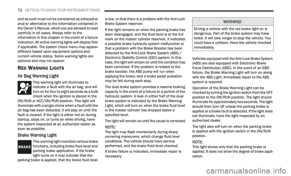
Air Bag Warning Light
This warning light will illuminate to
indicate a fault with the air bag, and will
t
u
rn on for four to eight seconds as a bulb
check when the ignition is placed in the
ON/RUN or ACC/ON/RUN position. This light will
illuminate with a single chime when a fault with the
air bag has been detected, it will stay on until the
fault is cleared. If the light is either not on during
startup, stays on, or turns on while driving, have
the system inspected at an authorized dealer as
soon as possible.
Brake Warning Light
This warning light monitors various brake
functions, including brake fluid level and
p a
rking brake application. If the brake
light turns on it may indicate that the
parking brake is applied, that the brake fluid level is low, or that there is a problem with the Anti-Lock
Brake System reservoir.
If the light remains on when the parking brake has
b
e
en disengaged, and the fluid level is at the full
mark on the master cylinder reservoir, it indicates
a possible brake hydraulic system malfunction or
that a problem with the Brake Booster has been
detected by the Anti-Lock Brake System (ABS) /
Electronic Stability Control (ESC) system. In this
case, the light will remain on until the condition has
been corrected. If the problem is related to the
brake booster, the ABS pump will run when
applying the brake, and a brake pedal pulsation
may be felt during each stop.
The dual brake system provides a reserve braking
c a
pacity in the event of a failure to a portion of the
hydraulic system. A leak in either half of the dual
brake system is indicated by the Brake Warning
Light, which will turn on when the brake fluid level
in the master cylinder has dropped below a
specified level.
The light will remain on until the cause is corrected.
NOTE:
The light may flash momentarily during sharp
c or
nering maneuvers, which change fluid level
conditions. The vehicle should have service
performed, and the brake fluid level checked.
If brake failure is indicated, immediate repair is
ne
cessary. Vehicles equipped with the Anti-Lock Brake System
(
A
BS) are also equipped with Electronic Brake
Force Distribution (EBD). In the event of an EBD
failure, the Brake Warning Light will turn on along
with the ABS Light. Immediate repair to the ABS
system is required.
Operation of the Brake Warning Light can be
c h
ecked by turning the ignition switch from the OFF
position to the ON/RUN position. The light should
illuminate for approximately two seconds. The light
should then turn off unless the parking brake is
applied or a brake fault is detected. If the light does
not illuminate, have the light inspected by an
authorized dealer.
The light also will turn on when the parking brake
i s
applied with the ignition switch in the ON/RUN
position.
NOTE:
This light shows only that the parking brake is
a p
plied. It does not show the degree of brake appli -
cation.
WARNING!
Driving a vehicle with the red brake light on is
dangerous. Part of the brake system may have
failed. It will take longer to stop the vehicle. You
could have a collision. Have the vehicle checked
immediately.
Page 75 of 268
GETTING TO KNOW YOUR INSTRUMENT PANEL 73
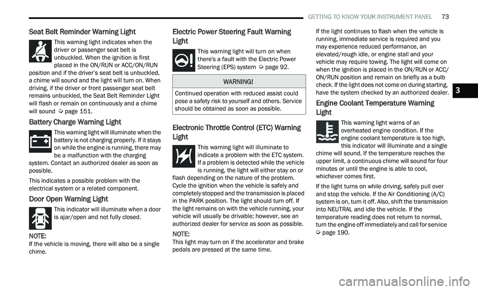
Seat Belt Reminder Warning Light
This warning light indicates when the
driver or passenger seat belt is
un
buckled. When the ignition is first
placed in the ON/RUN or ACC/ON/RUN
position and if the driver’s seat belt is unbuckled,
a chime will sound and the light will turn on. When
driving, if the driver or front passenger seat belt
remains unbuckled, the Seat Belt Reminder Light
will flash or remain on continuously and a chime
will sound
Ú page 151.
Battery Charge Warning Light
This warning light will illuminate when the
battery is not charging properly. If it stays
on
while the engine is running, there may
be a malfunction with the charging
system. Contact an authorized dealer as soon as
possible.
This indicates a possible problem with the
e l
ectrical system or a related component.
Door Open Warning Light
This indicator will illuminate when a door
is ajar/open and not fully closed.
NOTE:
If the vehicle is moving, there will also be a single
c h
ime.
Electric Power Steering Fault Warning
Light
This warning light will turn on when
there's a fault with the Electric Power
St
eering (EPS) system Ú page 92.
Electronic Throttle Control (ETC) Warning
Light
This warning light will illuminate to
indicate a problem with the ETC system.
I
f
a problem is detected while the vehicle
is running, the light will either stay on or
flash depending on the nature of the problem.
Cycle the ignition when the vehicle is safely and
completely stopped and the transmission is placed
in the PARK position. The light should turn off. If
the light remains on with the vehicle running, your
vehicle will usually be drivable; however, see an
authorized dealer for service as soon as possible.
NOTE:
This light may turn on if the accelerator and brake
p e
dals are pressed at the same time. If the light continues to flash when the vehicle is
r
u
nning, immediate service is required and you
may experience reduced performance, an
elevated/rough idle, or engine stall and your
vehicle may require towing. The light will come on
when the ignition is placed in the ON/RUN or ACC/
ON/RUN position and remain on briefly as a bulb
check. If the light does not come on during starting,
have the system checked by an authorized dealer.
Engine Coolant Temperature Warning
Light
This warning light warns of an
overheated engine condition. If the
e n
gine coolant temperature is too high,
this indicator will illuminate and a single
chime will sound. If the temperature reaches the
upper limit, a continuous chime will sound for four
minutes or until the engine is able to cool,
whichever comes first.
If the light turns on while driving, safely pull over
a n
d stop the vehicle. If the Air Conditioning (A/C)
system is on, turn it off. Also, shift the transmission
into NEUTRAL and idle the vehicle. If the
temperature reading does not return to normal,
turn the engine off immediately and call for service
Ú page 190.
WARNING!
Continued operation with reduced assist could
pose a safety risk to yourself and others. Service
should be obtained as soon as possible.3
Page 78 of 268
76 GETTING TO KNOW YOUR INSTRUMENT PANEL
When the engine is running, the MIL may flash to
alert serious conditions that could lead to
immediate loss of power or severe catalytic
converter damage. The vehicle should be serviced
by an authorized dealer as soon as possible if this
occurs.Service AWD Warning Light — If Equipped
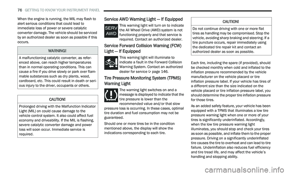
This warning light will turn on to indicate
the All Wheel Drive (AWD) system is not
fu
nctioning properly and that service is
required. Contact an authorized dealer.
Service Forward Collision Warning (FCW)
Light — If Equipped
This warning light will illuminate to
indicate a fault in the Forward Collision
W a
rning System. Contact an authorized
dealer for service
Ú page 146.
Tire Pressure Monitoring System (TPMS)
Warning Light
The warning light switches on and a
message is displayed to indicate that the
ti
re pressure is lower than the
recommended value and/or that slow
pressure loss is occurring. In these cases, optimal
tire duration and fuel consumption may not be
guaranteed.
Should one or more tires be in the condition
m e
ntioned above, the display will show the
indications corresponding to each tire. Each tire, including the spare (if provided), should
b
e
checked monthly when cold and inflated to the
inflation pressure recommended by the vehicle
manufacturer on the vehicle placard or tire
inflation pressure label. If your vehicle has tires of
a different size than the size indicated on the
vehicle placard or tire inflation pressure label, you
should determine the proper tire inflation pressure
for those tires.
As an added safety feature, your vehicle has been
e q
uipped with a TPMS that illuminates a low tire
pressure warning light when one or more of your
tires is significantly underinflated. Accordingly,
when the low tire pressure warning light
illuminates, you should stop and check your tires
as soon as possible, and inflate them to the proper
pressure. Driving on a significantly underinflated
tire causes the tire to overheat and can lead to tire
failure. Underinflation also reduces fuel efficiency
and tire tread life, and may affect the vehicle’s
handling and stopping ability.
WARNING!
A malfunctioning catalytic converter, as refer -
enced above, can reach higher temperatures
t h
an in normal operating conditions. This can
cause a fire if you drive slowly or park over flam -
mable substances such as dry plants, wood,
c a
rdboard, etc. This could result in death or seri -
ous injury to the driver, occupants or others.
CAUTION!
Prolonged driving with the Malfunction Indicator
Light (MIL) on could cause damage to the
vehicle control system. It also could affect fuel
economy and driveability. If the MIL is flashing,
severe catalytic converter damage and power
loss will soon occur. Immediate service is
required.
CAUTION!
Do not continue driving with one or more flat
tires as handling may be compromised. Stop the
vehicle, avoiding sharp braking and steering. If a
tire puncture occurs, repair immediately using
the dedicated tire repair kit and contact an
authorized dealer as soon as possible.