2021 CHRYSLER 300 ECO mode
[x] Cancel search: ECO modePage 93 of 268
STARTING AND OPERATING 91
In AutoStick mode, the transmission will shift up or
down when (+/-) is manually selected by the driver,
unless an engine lugging or overspeed condition
would result. It will remain in the selected gear
until another upshift or downshift is chosen, except
as described below.
If AutoStick is engaged while in DRIVE mode, the
transmission will automatically shift up when
maximum engine speed is reached. If the accel
-
erator is fully pressed, the transmission will
d ow
nshift when possible (based on current
vehicle speed and gear). Lack of accelerator
pedal activity will cause the transmission to
revert to automatic operation.
If AutoStick is engaged while the transmission
gear selector is in the SPORT position, manual
gear selection will be maintained until the gear
selector is returned to DRIVE, or as described
below. The transmission will not upshift auto -
matically at redline in this mode, nor will down -
shifts be obtained if the accelerator pedal is
p r
essed to the floor.
In either DRIVE or SPORT mode, the transmis -
sion will automatically downshift as the vehicle
s l
ows (to prevent engine lugging) and will
display the current gear.
The transmission will automatically downshift to
FIRST gear when coming to a stop. After a stop,
the driver should manually upshift (+) the trans -
mission as the vehicle is accelerated.
You can start out, from a stop, in FIRST or
SECOND gear. Tapping (+) at a stop will allow
starting in SECOND gear. Starting out in
SECOND gear can be helpful in snowy or icy
conditions.
If a requested downshift would cause the
engine to over-speed, that shift will not occur.
The system will ignore attempts to upshift at too
low of a vehicle speed.
Holding the (-) paddle pressed will downshift the
transmission to the lowest gear possible at the
current speed.
Transmission shifting will be more noticeable
when AutoStick is enabled.
The system may revert to automatic shift mode
if a fault or overheat condition is detected.
To disengage AutoStick mode, press and hold the
(+
) shift paddle until "D" or "S" is once again
indicated in the instrument cluster. Shifting out of
SPORT mode will also disable AutoStick. You can
shift in or out of AutoStick mode at any time
without taking your foot off the accelerator pedal.
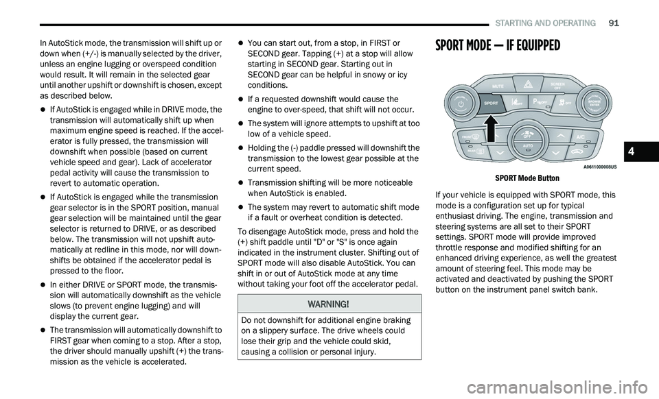
SPORT MODE — IF EQUIPPED
SPORT Mode Button
If your vehicle is equipped with SPORT mode, this
mod
e is a configuration set up for typical
enthusiast driving. The engine, transmission and
steering systems are all set to their SPORT
settings. SPORT mode will provide improved
throttle response and modified shifting for an
enhanced driving experience, as well the greatest
amount of steering feel. This mode may be
activated and deactivated by pushing the SPORT
button on the instrument panel switch bank.
WARNING!
Do not downshift for additional engine braking
on a slippery surface. The drive wheels could
lose their grip and the vehicle could skid,
causing a collision or personal injury.
4
Page 95 of 268
STARTING AND OPERATING 93
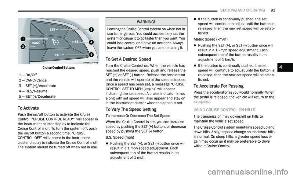
Cruise Control Buttons
To Activate
Push the on/off button to activate the Cruise
Control. “CRUISE CONTROL READY” will appear in
the instrument cluster display to indicate the
Cruise Control is on. To turn the system off, push
the on/off button a second time. “CRUISE
CONTROL OFF” will appear in the instrument
cluster display to indicate the Cruise Control is off.
The system should be turned off when not in use.
To Set A Desired Speed
Turn the Cruise Control on. When the vehicle has
reached the desired speed, push and release the
SET (+) or SET (-) button. Release the accelerator
and the vehicle will operate at the selected speed.
Once a speed has been set, a message “CRUISE
CONTROL SET TO MPH (km/h)” will appear
indicating the set speed. A cruise indicator lamp,
along with set speed will also appear and stay on
in the instrument cluster when the speed is set.
To Vary The Speed Setting
To Increase Or Decrease The Set Speed
When the Cruise Control is set, you can increase
sp
eed by pushing the SET (+) button, or decrease
speed by pushing the SET (-) button.
U.S. Speed (mph)
Pushing the SET (+) , or SET (-) button once will
result in a 1 mph speed adjustment. Each
s u
bsequent tap of the button results in an
adjustment of 1 mph.
If the button is continually pushed, the set
speed will continue to adjust until the button is
released, then the new set speed will be estab -
lished.
Metric Speed (km/h)
Pushing the SET (+), or SET (-) button once will
result in a 1 km/h speed adjustment. Each
s u
bsequent tap of the button results in an
adjustment of 1 km/h.
If the button is continually pushed, the set
speed will continue to adjust until the button is
released, then the new set speed will be estab -
lished.
To Accelerate For Passing
Press the accelerator as you would normally. When
the pedal is released, the vehicle will return to the
set speed.
USING CRUISE CONTROL ON HILLS
The transmission may downshift on hills to
maintain the vehicle set speed.
The Cruise Control system maintains speed up and
dow
n hills. A slight speed change on moderate hills
is normal. On steep hills, a greater speed loss or
gain may occur so it may be preferable to drive
without Cruise Control.
1 — On/Off
2 — CANC/Cancel
3 — SET (+)/Accelerate
4 — RES/Resume
5 — SET (-)/Decelerate
WARNING!
Leaving the Cruise Control system on when not in
use is dangerous. You could accidentally set the
system or cause it to go faster than you want. You
could lose control and have an accident. Always
leave the system OFF when you are not using it.
4
Page 100 of 268

98 STARTING AND OPERATING
When ACC Is Active:
NOTE:
When you use the SET (-) button to decelerate, if
the engine’s braking power does not slow the
vehicle sufficiently to reach the set speed, the
brake system will automatically slow the
vehicle.
The ACC system applies the brake down to a full
stop when following the vehicle in front. If your
vehicle follows the vehicle in front to a standstill,
your vehicle will release the brakes two seconds
after coming to a full stop.
The ACC will bring the vehicle to a complete stop
while following a vehicle in front and hold the
vehicle for two seconds in the stop position. If
the vehicle in front does not start moving within
two seconds, the ACC system will display a
message that the system will release the brakes
and that the brakes must be applied manually.
An audible chime will sound when the brakes
are released.
The ACC system maintains set speed when
driving uphill and downhill. However, a slight
speed change on moderate hills is normal. In
addition, downshifting may occur while climbing
uphill or descending downhill. This is normal
operation and necessary to maintain set speed.
When driving uphill and downhill, the ACC
system will cancel if the braking temperature
exceeds normal range (overheated).
Setting The Following Distance In ACC
The specified following distance for ACC can be set
by varying the distance setting between four bars
(longest), three bars (long), two bars (medium) and
one bar (short). Using this distance setting and the
vehicle speed, ACC calculates and sets the
distance to the vehicle ahead. This distance
setting displays in the instrument cluster display.
Distance Settings
To increase the distance setting, push the
D i
stance Setting Increase button and release.
Each time the button is pushed, the distance
setting increases by one bar (longer). To decrease the distance setting, push the
D
i
stance Setting Decrease button and release.
Each time the button is pushed, the distance
setting decreases by one bar (shorter).
If there is no vehicle ahead, the vehicle will
ma
intain the set speed. If a slower moving vehicle
is detected in the same lane, the instrument
cluster display will show the ACC Set With Target
Detected Indicator Light, and the system will adjust
the vehicle speed automatically to maintain the
distance setting, regardless of the set speed.
The vehicle will then maintain the set distance
u n
til:
The vehicle ahead accelerates to a speed above
the set speed.
The vehicle ahead moves out of your lane or
view of the sensor.
The distance setting is changed.
The system disengages Ú page 96.
The maximum braking applied by ACC is limited;
h ow
ever, the driver can always apply the brakes
manually, if necessary.
NOTE:
The brake lights will illuminate whenever the ACC
s y
stem applies the brakes.
A Proximity Warning will alert the driver if ACC
pr
edicts that its maximum braking level is not
sufficient to maintain the set distance. If this
1 — Longest Distance Setting (Four Bars)
2 — Medium Distance Setting (Two Bars)
3 — Long Distance Setting (Three Bars)
4 — Short Distance Setting (One Bar)
Page 112 of 268
110 STARTING AND OPERATING
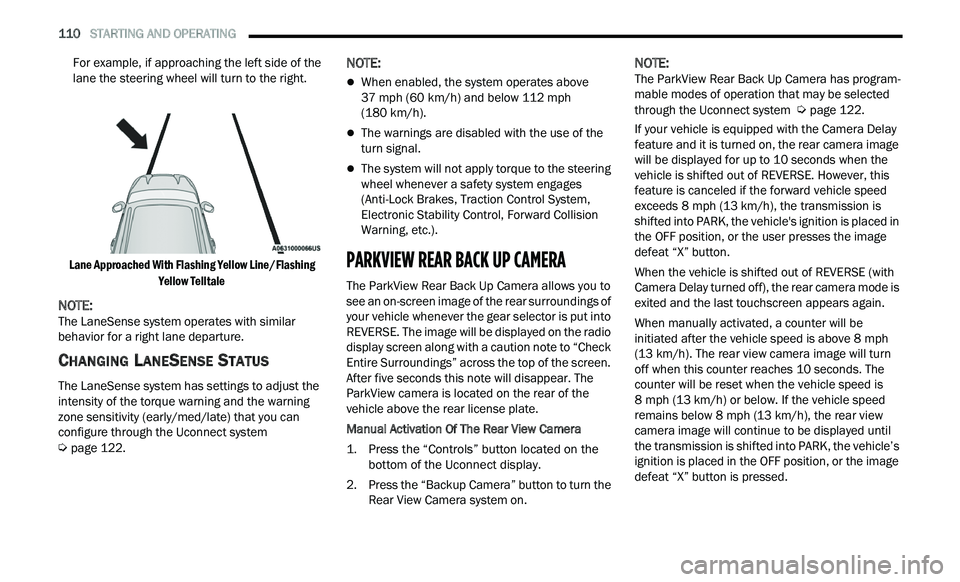
For example, if approaching the left side of the
lane the steering wheel will turn to the right.
Lane Approached With Flashing Yellow Line/Flashing Ye
llow Telltale
NOTE:
The LaneSense system operates with similar
b e
havior for a right lane departure.
CHANGING LANESENSE STATUS
The LaneSense system has settings to adjust the
intensity of the torque warning and the warning
zone sensitivity (early/med/late) that you can
configure through the Uconnect system
Ú page 122.
NOTE:
When enabled, the system operates above
37
mph (60 km/h) and below 112 mph
( 1
80 km/h).
The warnings are disabled with the use of the
turn signal.
The system will not apply torque to the steering
wheel whenever a safety system engages
(Anti-Lock Brakes, Traction Control System,
Electronic Stability Control, Forward Collision
Warning, etc.).
PARKVIEW REAR BACK UP CAMERA
The ParkView Rear Back Up Camera allows you to
see an on-screen image of the rear surroundings of
your vehicle whenever the gear selector is put into
REVERSE. The image will be displayed on the radio
display screen along with a caution note to “Check
Entire Surroundings” across the top of the screen.
After five seconds this note will disappear. The
ParkView camera is located on the rear of the
vehicle above the rear license plate.
Manual Activation Of The Rear View Camera
1. P
ress the “Controls” button located on the
b
ottom of the Uconnect display.
2. Press the “Backup Camera” button to turn the R
ear View Camera system on.
NOTE:
The ParkView Rear Back Up Camera has program -
mable modes of operation that may be selected
t h
rough the Uconnect system Ú page 122.
If your vehicle is equipped with the Camera Delay
f e
ature and it is turned on, the rear camera image
will be displayed for up to 10 seconds when the
vehicle is shifted out of REVERSE. However, this
feature is canceled if the forward vehicle speed
exceeds 8 mph (13 km/h), the transmission is
s h
ifted into PARK, the vehicle's ignition is placed in
the OFF position, or the user presses the image
defeat “X” button.
When the vehicle is shifted out of REVERSE (with
Ca
mera Delay turned off), the rear camera mode is
exited and the last touchscreen appears again.
When manually activated, a counter will be
i n
itiated after the vehicle speed is above 8 mph
( 1
3 km/h). The rear view camera image will turn
of f
when this counter reaches 10 seconds. The
counter will be reset when the vehicle speed is
8 mph (13 km/h) or below. If the vehicle speed
r e
mains below 8 mph (13 km/h), the rear view
c a
mera image will continue to be displayed until
the transmission is shifted into PARK, the vehicle’s
ignition is placed in the OFF position, or the image
defeat “X” button is pressed.
Page 126 of 268

124 MULTIMEDIA
Units
Display Brightness With Headlights OFF This setting will allow you to set the brightness when the headlights are off. To
a
c
cess this setting, Display Mode must be set to Manual. The “+” setting will
increase the brightness; the “-” will decrease the brightness.
Set Theme This setting will allow you to change the display theme.
Touchscreen Beep This setting will allow you to turn the touchscreen beep on or off.
Control Screen Timeout This setting will allow you to set the Control Screen to turn off automatically
af
ter five seconds or stay open until manually closed.
Navigation Next Turn Pop-ups Displayed in Cluster This setting will display navigation prompts in the Instrument Cluster Display.
Setting Name Description
When the Units button is pressed on the touchscreen, the system displays the different measurement options. The selected unit of measurement will display in
the instrument cluster display and navigation system (if equipped). The available settings are:
NOTE:
Depending on the vehicle’s options, feature settings may vary.
Setting Name Description
USThis setting will change the unit of measurement on the display to US.
Metric This setting will change the unit of measurement on the display to Metric.
Custom This setting changes the “Speed” (MPH or km/h), “Distance” (mi or km), “Fuel
Con
sumption” (MPG [US], MPG [UK], L/100 km, or km/L), “Pressure” (psi,
k P
a, or bar), and “Temperature” (°C or °F) units of measurement
independently.
Page 139 of 268
137
(Continued)
SAFETY
SAFETY FEATURES
ANTI-LOCK BRAKE SYSTEM (ABS)
The ABS provides increased vehicle stability and
brake performance under most braking conditions.
The system automatically prevents wheel lock and
enhances vehicle control during braking.
The ABS performs a self-check cycle to ensure that
th
e ABS is working properly each time the vehicle
is started and driven. During this self-check, you
may hear a slight clicking sound as well as some
related motor noises.
The ABS is activated during braking when the
s y
stem detects one or more wheels are beginning
to lock. Road conditions such as ice, snow, gravel,
bumps, railroad tracks, loose debris, or panic stops
may increase the likelihood of ABS activation(s).
You also may experience the following normal
c h
aracteristics when the ABS activates:
ABS motor noise or clicking sounds (you may
continue to hear for a short time after the stop).
Brake pedal pulsations.
A slight drop of the brake pedal at the end of the
stop. The ABS is designed to function with the Original
E
q
uipment Manufacturer (OEM) tires. Modification
may result in degraded ABS performance.
Anti-Lock Brake System (ABS) Warning
Light
The yellow ABS Warning Light will turn on when the
ignition is placed in the ON/RUN mode and may
stay on for as long as four seconds.
If the ABS Warning Light remains on or comes on
w h
ile driving, it indicates that the Anti-Lock portion
of the brake system is not functioning and that
service is required. However, the conventional
brake system will continue to operate normally if
the Anti-Lock Brake Warning Light is on.
If the ABS Warning Light is on, the brake system
s h
ould be serviced as soon as possible to restore
the benefits of Anti-Lock Brakes. If the Anti-Lock
WARNING!
The ABS contains sophisticated electronic
equipment that may be susceptible to interfer -
ence caused by improperly installed or high
out
put radio transmitting equipment. This
interference can cause possible loss of
anti-lock braking capability. Installation of
such equipment should be performed by qual -
ified professionals.
Pumping of the Anti-Lock Brakes will diminish
their effectiveness and may lead to a collision.
Pumping makes the stopping distance longer.
Just press firmly on your brake pedal when you
need to slow down or stop.
The ABS cannot prevent the natural laws of
physics from acting on the vehicle, nor can it
increase braking or steering efficiency beyond
that afforded by the condition of the vehicle
brakes and tires or the traction afforded.
The ABS cannot prevent collisions, including
those resulting from excessive speed in turns,
following another vehicle too closely, or hydro -
planing.
The capabilities of an ABS equipped vehicle
must never be exploited in a reckless or
dangerous manner that could jeopardize the
user’s safety or the safety of others.
WARNING!
6
Page 140 of 268
138 SAFETY
Brake Warning Light does not come on when the
ignition is placed in the ON/RUN mode, have the
light repaired as soon as possible.
ELECTRONIC BRAKE CONTROL (EBC)
S
YSTEM
Your vehicle is equipped with an advanced
Electronic Brake Control (EBC) system. This system
includes Anti-Lock Brake System (ABS), Brake
Assist System (BAS), Electronic Brake Force
Distribution (EBD), Electronic Roll Mitigation
(ERM), Electronic Stability Control (ESC), Hill Start
Assist (HSA), and Traction Control System (TCS).
These systems work together to enhance both
vehicle stability and control in various driving
conditions.
Your vehicle may also be equipped with Rain Brake
S u
pport (RBS) and Ready Alert Braking (RAB).
Brake System Warning Light
The red Brake System Warning Light will turn on
when the ignition is placed in the ON/RUN mode
and may stay on for as long as four seconds.
If the Brake System Warning Light remains on or
com
es on while driving, it indicates that the brake
system is not functioning properly and that
immediate service is required. If the Brake System
Warning Light does not come on when the ignition
is placed in the ON/RUN mode, have the light
repaired as soon as possible.
Brake Assist System (BAS)
The BAS is designed to optimize the vehicle’s
braking capability during emergency braking
maneuvers. The system detects an emergency
braking situation by sensing the rate and amount
of brake application and then applies optimum
pressure to the brakes. This can help reduce
braking distances. The BAS complements the
Anti-Lock Brake System (ABS). Applying the brakes
very quickly results in the best BAS assistance. To
receive the benefit of the system, you must apply
continuous braking pressure during the stopping
sequence (do not “pump” the brakes). Do not
reduce brake pedal pressure unless braking is no
longer desired. Once the brake pedal is released,
the BAS is deactivated.
Electronic Brake Force Distribution (EBD)
EBD manages the distribution of the braking
torque between the front and rear axles by limiting
braking pressure to the rear axle. This is done to
prevent overslip of the rear wheels to avoid vehicle
instability, and to prevent the rear axle from
entering the Anti-Lock Brake System (ABS) before
the front axle.
Electronic Roll Mitigation (ERM)
ERM anticipates the potential for wheel lift by
monitoring the driver’s steering wheel input and
the speed of the vehicle. When ERM determines
that the rate of change of the steering wheel angle
and vehicle’s speed are sufficient to potentially
cause wheel lift, it then applies the appropriate
brake and may also reduce engine power to lessen
the chance that wheel lift will occur. ERM can only
reduce the chance of wheel lift occurring during
severe or evasive driving maneuvers; it cannot
prevent wheel lift due to other factors, such as
road conditions, leaving the roadway, striking
objects or other vehicles.
NOTE:
ERM is disabled any time the ESC is in “Full Off”
m od
e (if equipped). See Ú page 139 in this
section for a complete explanation of the available
E S
C modes.
WARNING!
The Brake Assist System (BAS) cannot prevent
the natural laws of physics from acting on the
vehicle, nor can it increase the traction afforded
by prevailing road conditions. BAS cannot
prevent collisions, including those resulting from
excessive speed in turns, driving on very slippery
surfaces, or hydroplaning. The capabilities of a
BAS-equipped vehicle must never be exploited in
a reckless or dangerous manner, which could
jeopardize the user's safety or the safety of
others.
Page 141 of 268

SAFETY 139
(Continued)
Electronic Stability Control (ESC)
ESC enhances directional control and stability of
the vehicle under various driving conditions. ESC
corrects for oversteering or understeering of the
vehicle by applying the brake of the appropriate
wheel(s) to counteract the above conditions.
Engine power may also be reduced to help the
vehicle maintain the desired path.
Oversteer — when the vehicle is turning more
than appropriate for the steering wheel position.
Understeer — when the vehicle is turning less
than appropriate for the steering wheel position.
ESC uses sensors in the vehicle to determine the
ve
hicle path intended by the driver and compares
it to the actual path of the vehicle. When the actual
path does not match the intended path, ESC
applies the brake of the appropriate wheel to assist in counteracting the oversteer or understeer
condition.
The ESC Activation/Malfunction Indicator Light
l
oc
ated in the instrument cluster will start to flash
as soon as the ESC system becomes active. The
ESC Activation/Malfunction Indicator Light also
flashes when the TCS is active. If the ESC
Activation/Malfunction Indicator Light begins to
flash during acceleration, ease up on the
accelerator and apply as little throttle as possible.
Be sure to adapt your speed and driving to the
prevailing road conditions.
ESC Operating Modes
Depending upon model and mode of operation, the
ESC system may have multiple operating modes.
ESC On
This is the normal operating mode for the ESC.
W h
enever the vehicle is started, the ESC system
will be in this mode. This mode should be used for
most driving conditions. Alternate ESC modes
should only be used for specific reasons as noted
in the following paragraphs.
WARNING!
Many factors, such as vehicle loading, road condi -
tions and driving conditions, influence the chance
t h
at wheel lift or rollover may occur. ERM cannot
prevent all wheel lift or rollovers, especially those
that involve leaving the roadway or striking objects
or other vehicles. The capabilities of an ERM-
equipped vehicle must never be exploited in a
reckless or dangerous manner which could jeop -
ardize the user's safety or the safety of others.
WARNING!
Electronic Stability Control (ESC) cannot
prevent the natural laws of physics from acting
on the vehicle, nor can it increase the traction
afforded by prevailing road conditions. ESC
cannot prevent accidents, including those
resulting from excessive speed in turns, driving
on very slippery surfaces, or hydroplaning. ESC
also cannot prevent accidents resulting from
loss of vehicle control due to inappropriate
driver input for the conditions. Only a safe,
attentive, and skillful driver can prevent acci -
dents. The capabilities of an ESC equipped
v e
hicle must never be exploited in a reckless or
dangerous manner which could jeopardize the
user’s safety or the safety of others.
Vehicle modifications, or failure to properly
maintain your vehicle, may change the handling
characteristics of your vehicle, and may nega -
tively affect the performance of the ESC system.
C h
anges to the steering system, suspension,
braking system, tire type and size or wheel size
may adversely affect ESC performance. Improp -
erly inflated and unevenly worn tires may also
d e
grade ESC performance. Any vehicle modifi-
cation or poor vehicle maintenance that
r e
duces the effectiveness of the ESC system
can increase the risk of loss of vehicle control,
vehicle rollover, personal injury and death.
WARNING!
6