2021 CHRYSLER 300 change wheel
[x] Cancel search: change wheelPage 151 of 268

SAFETY 149
NOTE:
The TPMS is not intended to replace normal tire
care and maintenance or to provide warning of
a tire failure or condition.
The TPMS should not be used as a tire pressure
gauge while adjusting your tire pressure.
Driving on a significantly underinflated tire
causes the tire to overheat and can lead to tire
failure. Underinflation also reduces fuel effi
-
ciency and tire tread life, and may affect the
v e
hicle’s handling and stopping ability.
The TPMS is not a substitute for proper tire
maintenance, and it is the driver’s responsibility
to maintain correct tire pressure using an accu -
rate tire pressure gauge, even if underinflation
h a
s not reached the level to trigger illumination
of the TPMS Warning Light.
Seasonal temperature changes will affect tire
pressure, and the TPMS will monitor the actual
tire pressure in the tire.
The Tire Pressure Monitoring System (TPMS) uses
w i
reless technology with wheel rim mounted
electronic sensors to monitor tire pressure levels.
Sensors, mounted to each wheel as part of the
valve stem, transmit tire pressure readings to the
receiver module
Ú page 254.
NOTE:
It is particularly important for you to check the tire
p r
essure in all of the tires on your vehicle monthly
and to maintain the proper pressure.
The TPMS consists of the following components:
Receiver module.
Four Tire Pressure Monitoring System sensors.
Various Tire Pressure Monitoring System
messages, which display in the instrument
cluster.
Tire Pressure Monitoring System Warning Light.
Tire Pressure Monitoring System Low
Pressure Warnings
The Tire Pressure Monitoring System
(TPMS) Warning Light will illuminate in
t h
e instrument cluster and a chime will
sound when tire pressure is low in one or
more of the four active road tires. In addition, the
instrument cluster will display an “Inflate to XX”
message and a graphic showing the pressure
values of each tire with the low tire pressure values
shown in a different color.
CAUTION!
The TPMS has been optimized for the original
equipment tires and wheels. TPMS pressures
and warning have been established for the tire
size equipped on your vehicle. Undesirable
system operation or sensor damage may
result when using replacement equipment
that is not of the same size, type, and/or style.
The TPMS sensor is not designed for use on
aftermarket wheels and may contribute to a
poor overall system performance or sensor
damage. Customers are encouraged to use
Original Equipment Manufacturer (OEM)
wheels to ensure proper TPMS feature opera -
tion.
Using aftermarket tire sealants may cause the
Tire Pressure Monitoring System (TPMS)
sensor to become inoperable. After using an
aftermarket tire sealant it is recommended
that you take your vehicle to an authorized
dealer to have your sensor function checked.
After inspecting or adjusting the tire pressure
always reinstall the valve stem cap. This will
prevent moisture and dirt from entering the
valve stem, which could damage the TPMS
sensor.
6
Page 152 of 268

150 SAFETY
Tire Pressure Monitoring System Display
Low Tire Pressure Monitoring System Display
Should this occur, you should stop as soon as
p os
sible and inflate the tires with a low pressure
condition (those shown in a different color in the
instrument cluster graphic) to the vehicle’s
recommended cold placard pressure inflation
value as shown in the “Inflate to XX” message.
Once the system receives the updated tire pressures, the system will automatically update,
the graphic display in the instrument cluster will
change color back to the original color, and the
TPMS Warning Light will turn off. The vehicle may
need to be driven for up to 20
minutes above
1 5
mph (24 km/h) in order for the TPMS to receive
t h
is information.
NOTE:
When filling warm tires, the tire pressure may need
t o
be increased up to an additional 4 psi (28 kPa)
above the recommended cold placard pressure in
order to turn the TPMS Warning Light off.
Service Tire Pressure System Warning
If a system fault is detected, the Tire Pressure
Monitoring System (TPMS) Warning Light will flash
on and off for 75 seconds and then remain on
solid. The system fault will also sound a chime. In
addition, the instrument cluster will display a
"Service Tire Pressure System" message for a
minimum of five seconds and then display dashes
(- -) in place of the pressure value to indicate which
sensor is not being received.
If the ignition switch is cycled, this sequence will
r e
peat, providing the system fault still exists. If the
system fault no longer exists, the TPMS Warning
Light will no longer flash, and the "Service Tire
Pressure System" message will no longer display,
and a pressure value will display in place of the
dashes. A system fault can occur due to any of the
following:
Signal interference due to electronic devices or
driving next to facilities emitting the same radio
frequencies as the TPMS sensors.
Accumulation of snow or ice around the wheels
or wheel housings.
Using tire chains on the vehicle.
Using wheels/tires not equipped with TPMS
sensors.
Vehicles With Compact Spare
1. T he compact spare tire or non-matching full
s
ize does not have a Tire Pressure Monitoring
System sensor. Therefore, the TPMS will not
monitor the pressure in the compact spare
tire.
2. I f you install the compact or non-matching full
s
ize spare tire in place of a road tire that has a
pressure below the low-pressure warning limit,
upon the next ignition key cycle, the TPMS
Warning Light will remain on and a chime will
sound. In addition, the graphic in the
instrument cluster will still display a different
color pressure value and an "Inflate to XX"
message.
Page 167 of 268
SAFETY 165
NOTE:
After an accident, remember to cycle the ignition to
t h
e STOP (OFF/LOCK) position and remove the key
from the ignition switch to avoid draining the
battery. Carefully check the vehicle for fuel leaks in
the engine compartment and on the ground near
the engine compartment and fuel tank before
resetting the system and starting the engine. If
there are no fuel leaks or damage to the vehicle
electrical devices (e.g. headlights) after an
accident, reset the system by following the
procedure described below. If you have any doubt,
contact an authorized dealer.
Enhanced Accident Response System
Reset Procedure
In order to reset the Enhanced Accident Response
System functions after an event, the ignition switch
must be changed from ignition START or ON/RUN
to ignition OFF. Carefully check the vehicle for fuel
leaks in the engine compartment and on the
ground near the engine compartment and fuel
tank before resetting the system and starting the
engine.
After an accident, if the vehicle will not start after
p e
rforming the reset procedure, the vehicle must
be towed to an authorized dealer to be inspected
and to have the Enhanced Accident Response
System reset.
Maintaining Your Air Bag System Event Data Recorder (EDR)
This vehicle is equipped with an event data
recorder (EDR). The main purpose of an EDR is to
record, in certain crash or near crash-like
situations, such as an air bag deployment or hitting
a road obstacle, data that will assist in
understanding how a vehicle’s systems performed.
The EDR is designed to record data related to
vehicle dynamics and safety systems for a short
period of time, typically 30 seconds or less. The
EDR in this vehicle is designed to record such data
as:
How various systems in your vehicle were oper -
ating;
Whether or not the driver and passenger safety
belts were buckled/fastened;
How far (if at all) the driver was depressing the
accelerator and/or brake pedal; and,
How fast the vehicle was traveling.
These data can help provide a better
u n
derstanding of the circumstances in which
crashes and injuries occur.
NOTE:
EDR data are recorded by your vehicle only if a
n on
-trivial crash situation occurs; no data are
recorded by the EDR under normal driving condi -
tions and no personal data (e.g., name, gender,
a g
e, and crash location) are recorded. However,
other parties, such as law enforcement, could
WARNING!
Modifications to any part of the air bag system
could cause it to fail when you need it. You
could be injured if the air bag system is not
there to protect you. Do not modify the compo -
nents or wiring, including adding any kind of
ba
dges or stickers to the steering wheel hub
trim cover or the upper passenger side of the
instrument panel. Do not modify the front
fascia/bumper, vehicle body structure, or add
aftermarket side steps or running boards.
It is dangerous to try to repair any part of the
air bag system yourself. Be sure to tell anyone
who works on your vehicle that it has an air
bag system.
Do not attempt to modify any part of your air
bag system. The air bag may inflate accidentally
or may not function properly if modifications are
made. Take your vehicle to an authorized dealer
for any air bag system service. If your seat,
including your trim cover and cushion, needs to
be serviced in any way (including removal or
loosening/tightening of seat attachment bolts),
take the vehicle to an authorized dealer. Only
manufacturer approved seat accessories may
be used. If it is necessary to modify the air bag
system for persons with disabilities, contact an
authorized dealer.
6
Page 184 of 268
182 IN CASE OF EMERGENCY
(Continued)
LTE (voice/data) or 4G (data) network conges-
tion.
Weather.
Buildings, structures, geographic terrain, or
tunnels.
NOTE:
Your vehicle may be transmitting data as autho -
rized by the subscriber.
Never place anything on or near the vehicle’s LTE
(voice/data) or 4G (data) and GPS antennas. You
could prevent LTE (voice/data) or 4G (data) and
GPS signal reception, which can prevent your
vehicle from placing an emergency call. An oper -
able LTE (voice/data) or 4G (data) network
c o
nnection and a GPS signal is required for the
SOS Call system to function properly.
Changes or modifications not expressly
approved by the party responsible for compli -
ance could void the user's authority to operate
t h
e equipment.
Automatic SOS — If Equipped
Automatic SOS is a hands-free safety service that
c a
n immediately connect you with help in the event
that your vehicle’s airbags deploy. Please refer to
your provided radio supplement for complete
information.
JACKING AND TIRE CHANGINGPREPARATIONS FOR JACKING
1. Park the vehicle on a firm, level surface. Avoid ice or slippery areas.
2. T urn on the Hazard Warning Flashers.
WARNING!
ALWAYS obey traffic laws and pay attention to
the road. ALWAYS drive safely with your hands on
the steering wheel. You have full responsibility
and assume all risks related to the use of the
Uconnect and SiriusXM Guardian™ features and
applications in this vehicle. Only use Uconnect
features and SiriusXM Guardian™ services when
it is safe to do so. Failure to do so may result in
an accident involving serious injury or death.
CAUTION!
To avoid damage to the mirror during cleaning,
never spray any cleaning solution directly onto
the mirror. Apply the solution onto a clean cloth
and wipe the mirror clean.
WARNING!
Do not attempt to change a tire on the side of
the vehicle close to moving traffic. Pull far
enough off the road to avoid the danger of
being hit when operating the jack or changing
the wheel.
Being under a jacked-up vehicle is dangerous.
The vehicle could slip off the jack and fall on
you. You could be crushed. Never put any part
of your body under a vehicle that is on a jack.
If you need to get under a raised vehicle, take
it to a service center where it can be raised on
a lift.
Never start or run the engine while the vehicle
is on a jack.
The jack is designed to be used as a tool for
changing tires only. The jack should not be
used to lift the vehicle for service purposes.
The vehicle should be jacked on a firm level
surface only. Avoid ice or slippery areas.
WARNING!
Do not attempt to change a tire on the side of
the vehicle close to moving traffic. Pull far
enough off the road to avoid being hit when
operating the jack or changing the wheel.
WARNING!
Page 185 of 268
IN CASE OF EMERGENCY 183
3. Apply the parking brake.
4. P lace the gear selector into PARK (P).
5
. T urn the ignition to the OFF position.
6
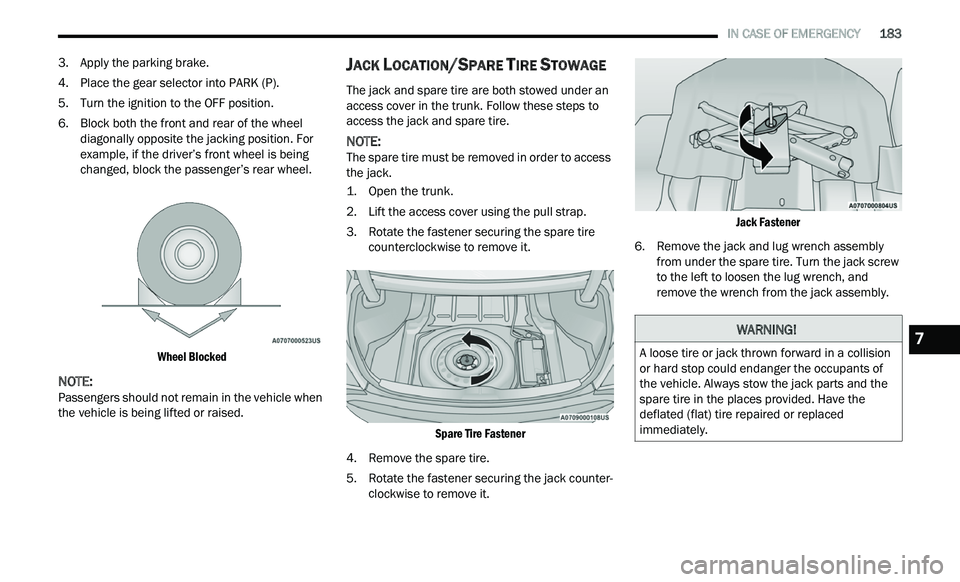
. B lock both the front and rear of the wheel
d
iagonally opposite the jacking position. For
example, if the driver’s front wheel is being
changed, block the passenger’s rear wheel.
Wheel Blocked
NOTE:
Passengers should not remain in the vehicle when
t h
e vehicle is being lifted or raised.
JACK LOCATION/SPARE TIRE STOWAGE
The jack and spare tire are both stowed under an
access cover in the trunk. Follow these steps to
access the jack and spare tire.
NOTE:
The spare tire must be removed in order to access
t h
e jack.
1. Open the trunk.
2
. Li ft the access cover using the pull strap.
3
. R otate the fastener securing the spare tire
c
ounterclockwise to remove it.
Spare Tire Fastener
4. R emove the spare tire.
5
. R otate the fastener securing the jack counter -
c
lockwise to remove it.
Jack Fastener
6. R emove the jack and lug wrench assembly
f
rom under the spare tire. Turn the jack screw
to the left to loosen the lug wrench, and
remove the wrench from the jack assembly.
WARNING!
A loose tire or jack thrown forward in a collision
or hard stop could endanger the occupants of
the vehicle. Always stow the jack parts and the
spare tire in the places provided. Have the
deflated (flat) tire repaired or replaced
immediately.7
Page 186 of 268
184 IN CASE OF EMERGENCY
(Continued)
JACKING AND CHANGING A TIRE
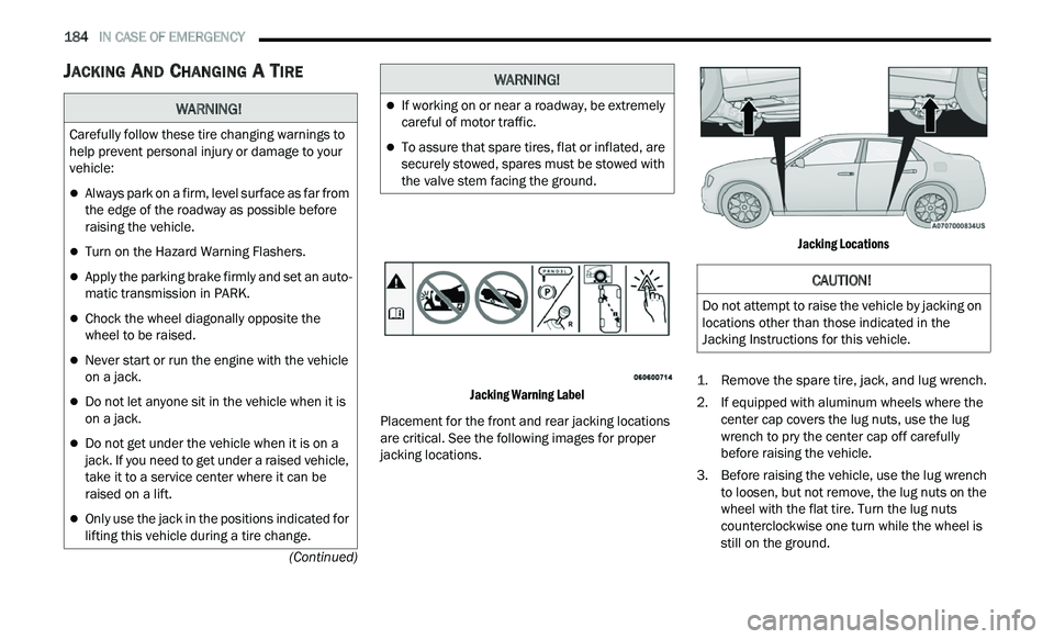
Jacking Warning Label
Placement for the front and rear jacking locations
ar
e critical. See the following images for proper
jacking locations.
Jacking Locations
1. R emove the spare tire, jack, and lug wrench.
2
. I f equipped with aluminum wheels where the
c
enter cap covers the lug nuts, use the lug
wrench to pry the center cap off carefully
before raising the vehicle.
3. Before raising the vehicle, use the lug wrench t
o loosen, but not remove, the lug nuts on the
wheel with the flat tire. Turn the lug nuts
counterclockwise one turn while the wheel is
still on the ground.
WARNING!
Carefully follow these tire changing warnings to
help prevent personal injury or damage to your
vehicle:
Always park on a firm, level surface as far from
the edge of the roadway as possible before
raising the vehicle.
Turn on the Hazard Warning Flashers.
Apply the parking brake firmly and set an auto -
matic transmission in PARK.
Chock the wheel diagonally opposite the
wheel to be raised.
Never start or run the engine with the vehicle
on a jack.
Do not let anyone sit in the vehicle when it is
on a jack.
Do not get under the vehicle when it is on a
jack. If you need to get under a raised vehicle,
take it to a service center where it can be
raised on a lift.
Only use the jack in the positions indicated for
lifting this vehicle during a tire change.
If working on or near a roadway, be extremely
careful of motor traffic.
To assure that spare tires, flat or inflated, are
securely stowed, spares must be stowed with
the valve stem facing the ground.
WARNING!
CAUTION!
Do not attempt to raise the vehicle by jacking on
locations other than those indicated in the
Jacking Instructions for this vehicle.
Page 200 of 268
198 SERVICING AND MAINTENANCE
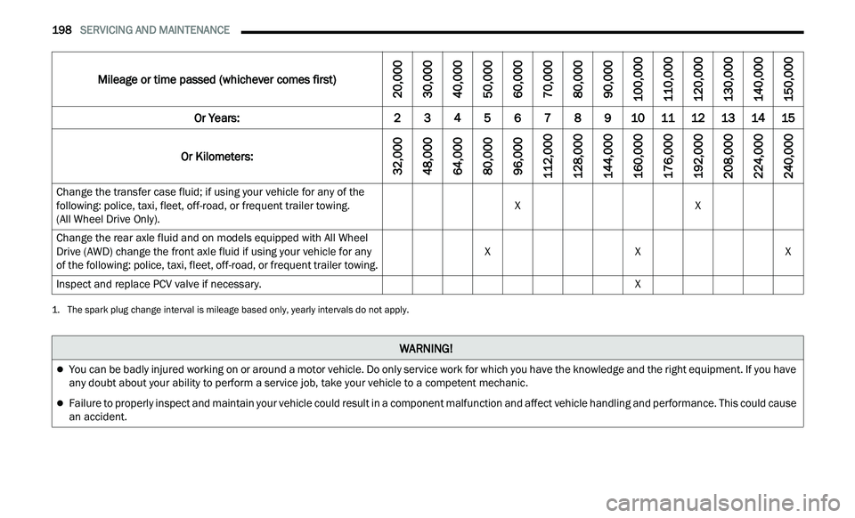
Change the transfer case fluid; if using your vehicle for any of the
following: police, taxi, fleet, off-road, or frequent trailer towing.
(All Wheel Drive Only). X
X
Change the rear axle fluid and on models equipped with All Wheel
D r
ive (AWD) change the front axle fluid if using your vehicle for any
of the following: police, taxi, fleet, off-road, or frequent trailer towing. X
XX
Inspect and replace PCV valve if necessary. X
1. The spark plug change interval is mileage based only, yearly intervals do not apply.
Mileage or time passed (whichever comes first)
20,000
30,000
40,000
50,000
60,000
70,000
80,000
90,000
100,000
110,000
120,000
130,000
140,000
150,000
Or Years: 2 3 4 5 6 7 8 9 10 11 12 13 14 15
Or Kilometers:
32,000
48,000
64,000
80,000
96,000
112,000
128,000
144,000
160,000
176,000
192,000
208,000
224,000
240,000
WARNING!
You can be badly injured working on or around a motor vehicle. Do only service work for which you have the knowledge and the right equipment. If you have
any doubt about your ability to perform a service job, take your vehicle to a competent mechanic.
Failure to properly inspect and maintain your vehicle could result in a component malfunction and affect vehicle handling and performance. This could cause
an accident.
Page 215 of 268
SERVICING AND MAINTENANCE 213
Fluid Level Check
The fluid level is preset at the factory and does not
require adjustment under normal operating
conditions. Routine fluid level checks are not
required; therefore the transmission has no
dipstick. An authorized dealer can check your
transmission fluid level using special service tools.
If you notice fluid leakage or transmission
malfunction, visit an authorized dealer
immediately to have the transmission fluid level
checked. Operating the vehicle with an improper
fluid level can cause severe transmission damage.
Fluid And Filter Changes
Under normal operating conditions, the fluid
installed at the factory will provide satisfactory
lubrication for the life of the vehicle.
Routine fluid and filter changes are not required.
How e
ver, change the fluid and filter if the fluid
becomes contaminated (with water, etc.), or if the
transmission is disassembled for any reason.
Selection Of Lubricant
It is important to use the proper transmission fluid
to ensure optimum transmission performance and
life. Use only the manufacturer's specified
transmission fluid
Ú page 250. It is important to
maintain the transmission fluid at the correct level
u s
ing the recommended fluid.
NOTE:
No chemical flushes should be used in any trans -
mission; only the approved lubricant should be
u s
ed.
ALL WHEEL DRIVE (AWD) —
I
F EQUIPPED
The All Wheel Drive system consists of a transfer
case and front differential. The exterior surface of
these components should be inspected for
evidence of fluid leaks. Confirmed leaks should be
repaired as soon as possible.
The transfer case fluid fill/inspection plug is
l oc
ated in the middle of the rear housing. To
inspect the transfer case fluid level, remove the
fill/inspection plug. The fluid level should be even
with the bottom of the hole. Use this plug to add
fluid as required.
The front differential fill plug is located on the outer
cov
er near the half shaft attachment. To inspect
the differential fluid level, remove the fill plug. The
fluid level should be even with or slightly below the
bottom of the hole.
Fluid Changes
For the proper maintenance intervals Ú page 195.
REAR AXLE
For normal service, periodic fluid level checks are
not required. When the vehicle is serviced for other
reasons the exterior surfaces of the axle assembly
should be inspected. If gear oil leakage is
suspected inspect the fluid level
Ú page 250.
CAUTION!
Do not use chemical flushes in your
transmission as the chemicals can damage your
transmission components. Such damage is not
covered by the New Vehicle Limited Warranty.
CAUTION!
If a transmission fluid leak occurs, visit an
authorized dealer immediately. Severe
transmission damage may occur. An authorized
dealer has the proper tools to adjust the fluid
level accurately.CAUTION!
Using a transmission fluid other than the
manufacturer’s recommended fluid may cause
deterioration in transmission shift quality and/or
torque converter shudder
Ú page 250.
8