2021 CHRYSLER 300 change wheel
[x] Cancel search: change wheelPage 51 of 268
GETTING TO KNOW YOUR VEHICLE 49
The speeds can be selected using either the
blower control knob on the faceplate or the
buttons on the touchscreen.
Faceplate
The blower speed increases as you turn the blower
c
on
trol knob clockwise from the lowest blower
setting. The blower speed decreases as you turn
the blower control knob counterclockwise.
Touchscreen
Use the small blower icon to reduce the blower
s e
tting and the large blower icon to increase the
blower setting. Blower can also be selected by
pressing the blower bar area between the icons.
Mode Control
Select Mode by pressing one of the Mode
buttons on the touchscreen to change
t h
e airflow distribution mode. The airflow
distribution mode can be adjusted so air
comes from the instrument panel outlets, floor
outlets, defrost outlets, and demist outlets.
Panel Mode
Air comes from the outlets in the
instrument panel. Each of these outlets
c a
n be individually adjusted to direct the
flow of air. The air vanes of the center
outlets and outboard outlets can be moved up and
down or side to side to regulate airflow direction.
There is a shut off wheel located below the air vanes to shut-off or adjust the amount of airflow
from these outlets.
Bi-Level Mode
Air comes from the instrument panel
outlets and floor outlets. A slight amount
of
air is directed through the defrost and
side window demister outlets.
NOTE:
Bi-Level mode is designed under comfort condi -
tions to provide cooler air out of the panel outlets
a n
d warmer air from the floor outlets.
Floor Mode
Air comes from the floor outlets. A slight
amount of air is directed through the
de
frost and side window demister
outlets.
Mix Mode
Air is directed through the floor, defrost,
and side window demister outlets. This
s e
tting works best in cold or snowy
conditions that require extra heat to the
windshield. This setting is good for maintaining
comfort while reducing moisture on the windshield.
Climate Control OFF Button
Press and release the OFF button on the
touchscreen, or push the OFF button on
t h
e faceplate to turn the Climate Control
ON/OFF.
AUTOMATIC TEMPERATURE CONTROL
(ATC)
Automatic Operation
1. Push the AUTO button on the faceplate, or
press and release the AUTO button on the
touchscreen on the Automatic Temperature
Control (ATC) Panel.
2. Next, adjust the temperature you would like t
he system to maintain by adjusting the driver
and passenger temperature control buttons.
Once the desired temperature is displayed, the
system will achieve and automatically
maintain that comfort level.
3. When the system is set up for your comfort l
evel, it is not necessary to change the
settings. You will experience the greatest
efficiency by simply allowing the system to
function automatically.
NOTE:
It is not necessary to change the temperature
settings for cold or hot vehicles. The system
automatically adjusts the temperature, mode,
and blower speed to provide comfort as quickly
as possible.
The temperature can be displayed in U.S. or
Metric units within Uconnect Settings
Ú page 122.
2
Page 69 of 268

GETTING TO KNOW YOUR INSTRUMENT PANEL 67
Instrument Cluster Display Controls
Up And Down Arrow Buttons:
Using the up
or down arrow buttons allows
you to cycle through the Main Menu Items.
Changes the Main Screen area and Menu Title
a r
ea.
Left And Right Arrow Buttons:
Using the left
or right arrow button allows
you to cycle through the submenu items of the
M a
in menu item.
NOTE:
Holding the up / down or left / right
a
rrow button will loop the user through the
c u
rrently selected menu or options presented
on the screen.
Upon returning to a main menu, the last
submenu screen viewed within that main menu
will be displayed.
OK Button:
For Digital Speedometer:
Pushing the OK button changes units (mph or
km/h).
For Screen Setup:
OK button allows user to enter menu and
submenus.
Within each submenu layer, the up and
down arrow buttons will allow the user to
select the item of interest.
Pushing the OK button makes the selection. A
confirmation screen will appear, returning the
user to the first page of the submenu.
Pushing the left arrow button will exit each
submenu layer and return to the main menu.
For the Trip and Fuel Economy menus:
Information is reset by pushing and holding the
OK button.
ENGINE OIL LIFE RESET
Oil Change Required
Your vehicle is equipped with an engine oil change
in
dicator system. The “Oil Change Required”
message will display in the instrument cluster
display for five seconds after a single chime has
sounded, to indicate the next scheduled oil change
interval. The engine oil change indicator system is
duty cycle based, which means the engine oil
change interval may fluctuate, dependent upon
your personal driving style.
Unless reset, this message will continue to display
e a
ch time you place the ignition in the ON/RUN
position. To turn off the message temporarily, push
and release the OK or arrow buttons. To reset the
oil change indicator system (after performing the
scheduled maintenance), refer to the following
procedure.
Vehicles Equipped With Keyless Enter ‘N Go™ —
I g
nition
Use the steering wheel instrument cluster display
con
trols for the following procedure(s):
1. Without pressing the brake pedal, push the E
NGINE START/STOP button and place the
ignition in the ON/RUN position (do not start
the engine).
1 — Left Arrow Button
2 — Up Arrow Button
3 — Right Arrow Button
4 — Down Arrow Button
5 — OK Button
3
Page 70 of 268

68 GETTING TO KNOW YOUR INSTRUMENT PANEL
2. Push and release the down arrow button to
scroll downward through the main menu to
“ V
ehicle Info.”
3. P ush and release the right
arrow button to
access the ”Oil Life” screen.
4. P ush and hold the O
K button to reset oil life. If
conditions are met, the gauge and numeric
display will update to show 100%. If conditions
are not met a pop-up message of "To reset oil
life engine must be off with ignition in run" will
be displayed (for five seconds), and the user
will remain at the Oil Life screen.
5. P ush and release the u
p or down arrow
button to exit the submenu screen.
NOTE:
If the indicator message illuminates when you start
t h
e vehicle, the oil change indicator system did not
reset. If necessary, repeat this procedure.
Secondary Method Of Resetting Engine Oil Life
1. W ithout pressing the brake pedal, push the
E
NGINE START/STOP button and place the
ignition to the ON/RUN position (do not start
the engine).
2. Fully press the accelerator pedal, slowly, three t
imes within ten seconds.
3. Without pushing the brake pedal, push the E
NGINE START/STOP button once to return the
ignition to the OFF position.
NOTE:
If the indicator message illuminates when you start
t h
e vehicle, the oil change indicator system did not
reset. If necessary, repeat this procedure.
INSTRUMENT CLUSTER DISPLAY
S
ELECTABLE MENU ITEMS
Push and release the up or down arrow
button until the desired Selectable Menu item is
d i
splayed in the instrument cluster display.
Follow the Menu or submenu prompts as desired.
Speedometer
Push and release the OK button to toggle between
mph and km/h.
Vehicle Info
The Vehicle Info consists of the following submenu
(pushing the left or right arrow button will
allow you to scroll through the submenu):
Tire Pressure Monitor
Coolant Temperature
Transmission Temperature
Oil Temperature
Oil Pressure
Oil Life
AWD Status — If Equipped
Battery Voltage
Driver Assist — If Equipped
The Driver Assist menu provides the status and a
visual about the Adaptive Cruise Control and
LaneSense features. When they are both off the
screen, the display will read "Adaptive Cruise
Control (ACC) and LaneSense Off."
Adaptive Cruise Control (ACC) Feature —
If Equipped
The instrument cluster display displays the current
A C
C system settings Ú page 94. The information
displayed depends on ACC system status.
Push the ACC ON/OFF button (located on the
s t
eering wheel) until one of the following displays
in the instrument cluster display:
Adaptive Cruise Control Off
When ACC is deactivated, the display will read
“ A
daptive Cruise Control Off.”
Adaptive Cruise Control Ready
When ACC is activated but the vehicle speed
s e
tting has not been selected, the display will read
“Adaptive Cruise Control Ready.”
Push the SET + or the SET- button (located on the
s t
eering wheel) and the following will display in the
instrument cluster display:
ACC Set
When ACC is set, the set speed will display in the
i n
strument cluster.
Page 73 of 268
GETTING TO KNOW YOUR INSTRUMENT PANEL 71
NOTE:
The charging system is independent from load
reduction. The charging system performs a diag
-
nostic on the charging system continuously.
If the Battery Charge Warning Light is on it may
indicate a problem with the charging system
Ú page 73.
The electrical loads that may be switched off (if
e q
uipped), and vehicle functions which can be
affected by load reduction:
Heated Seat/Vented Seats/Heated Wheel —
If Equipped
Heated/Cooled Cup Holders — If Equipped
Rear Defroster And Heated Mirrors
HVAC System
115 Volts AC Power Inverter System
Audio and Telematics System
Loss of the battery charge may indicate one or
m or
e of the following conditions:
The charging system cannot deliver enough
electrical power to the vehicle system because
the electrical loads are larger than the capability
of the charging system. The charging system is
still functioning properly.
Turning on all possible vehicle electrical loads
(e.g. HVAC to max settings, exterior and interior
lights, overloaded power outlets +12 Volts, 115 Volts AC, USB ports) during certain driving
c
on
ditions (city driving, towing, frequent stop -
ping).
Installing options like additional lights, upfitter
electrical accessories, audio systems, alarms
and similar devices.
Unusual driving cycles (short trips separated by
long parking periods).
The vehicle was parked for an extended period
of time (weeks, months).
The battery was recently replaced and was not
charged completely.
The battery was discharged by an electrical load
left on when the vehicle was parked.
The battery was used for an extended period
with the engine not running to supply radio,
lights, chargers, +12 Volt portable appliances
like vacuum cleaners, game consoles and
similar devices.
What to do when an electrical load reduction
a c
tion message is present (“Battery Saver On” or
“Battery Saver Mode”)
During a trip:
Reduce power to unnecessary loads if possible:
Turn off redundant lights (interior or exte -
rior)
Check what may be plugged in to power
outlets +12 Volts, 115 Volts AC, USB ports
Check HVAC settings (blower, temperature)
Check the audio settings (volume)
After a trip:
Check if any aftermarket equipment was
installed (additional lights, upfitter electrical
accessories, audio systems, alarms) and review
specifications if any (load and Ignition Off Draw
currents).
Evaluate the latest driving cycles (distance,
driving time and parking time).
The vehicle should have service performed if
the message is still present during consecutive
trips and the evaluation of the vehicle and
driving pattern did not help to identify the cause.
PROGRAMMABLE FEATURES
The instrument cluster display can be used to view
or change the following settings. Push the up
or
down arrow button to scroll through the main
menus, then push the ri
ght arrow button to
scroll through the submenus of each menu item.
P u
sh the left arrow button to scroll back to a
previous menu or submenu.
WARNING LIGHTS AND MESSAGES
The warning/indicator lights will illuminate in the
instrument panel together with a dedicated
message and/or acoustic signal when applicable.
These indications are indicative and precautionary
3
Page 110 of 268
108 STARTING AND OPERATING
LANESENSE — IF EQUIPPED
LANESENSE OPERATION
The LaneSense system is operational at speeds
above 37 mph (60 km/h) and below 112 mph
( 1
80 km/h). The LaneSense system uses a
f or
ward looking camera to detect lane markings
and measure vehicle position within the lane
boundaries.
When both lane markings are detected and the
dr
iver unintentionally drifts out of the lane (no turn
signal applied), the LaneSense system provides a
haptic warning in the form of torque applied to the
steering wheel to prompt the driver to remain
within the lane boundaries. If the driver
unintentionally drifts out of the lane, the
LaneSense system provides a visual warning
through the instrument cluster display to prompt
the driver to remain within the lane boundaries.
The driver may manually override the haptic
w a
rning by applying torque into the steering wheel
at any time.
When only a single lane marking is detected and
t h
e driver unintentionally drifts across the lane
marking (no turn signal applied), the LaneSense
system provides visual warnings through the
instrument cluster display to prompt the driver to remain within the lane. When only a single lane
marking is detected, a haptic (torque) warning will
not be provided.
NOTE:
When operating conditions have been met, the
La n
eSense system will monitor if the driver’s
hands are on the steering wheel and provide an
audible warning to the driver if removed. The
system will cancel if the driver does not return their
hands to the wheel.
TURNING LANESENSE ON OR OFF
The LaneSense button is located on the
center stack below the Uconnect display.
To turn the LaneSense system on, push the
Lan
eSense button (LED turns off). A “LaneSense
On” message is shown in the instrument cluster
display.
To turn the LaneSense system off, push the
Lan
eSense button once (LED turns on). A
“LaneSense Off” message is shown in the
instrument cluster display.
NOTE:
The LaneSense system will retain the last system
s t
ate, on or off, from the last ignition cycle when
the ignition is changed to the ON/RUN position.
LANESENSE WARNING MESSAGE
The LaneSense system will indicate the current
lane drift condition through the instrument cluster
display.
Premium Instrument Cluster Display
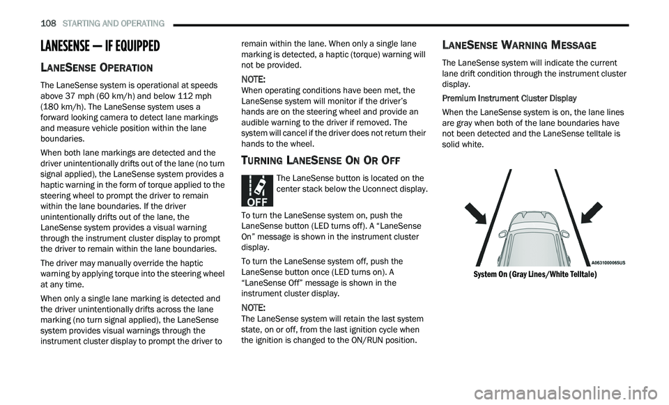
When the LaneSense system is on, the lane lines
a r
e gray when both of the lane boundaries have
not been detected and the LaneSense telltale is
solid white.
System On (Gray Lines/White Telltale)
Page 111 of 268
STARTING AND OPERATING 109
Left Lane Departure — Only Left Lane Detected
When the LaneSense system is on, the Lane-
Sense telltale is solid white when only the left
l a
ne marking has been detected and the system
is ready to provide visual warnings in the instru -
ment cluster display if an unintentional lane
d e
parture occurs.
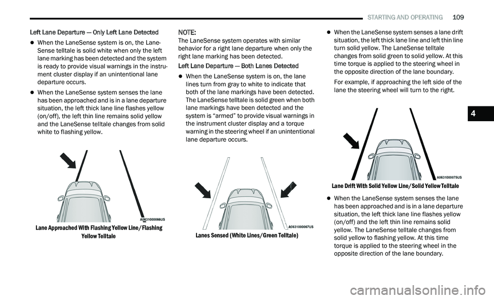
When the LaneSense system senses the lane
has been approached and is in a lane departure
situation, the left thick lane line flashes yellow
(on/off), the left thin line remains solid yellow
and the LaneSense telltale changes from solid
white to flashing yellow.
Lane Approached With Flashing Yellow Line/Flashing Ye
llow Telltale
NOTE:
The LaneSense system operates with similar
b e
havior for a right lane departure when only the
right lane marking has been detected.
Left Lane Departure — Both Lanes Detected
When the LaneSense system is on, the lane
lines turn from gray to white to indicate that
both of the lane markings have been detected.
The LaneSense telltale is solid green when both
lane markings have been detected and the
system is “armed” to provide visual warnings in
the instrument cluster display and a torque
warning in the steering wheel if an unintentional
lane departure occurs.
Lanes Sensed (White Lines/Green Telltale)
When the LaneSense system senses a lane drift
situation, the left thick lane line and left thin line
turn solid yellow. The LaneSense telltale
changes from solid green to solid yellow. At this
time torque is applied to the steering wheel in
the opposite direction of the lane boundary.
For example, if approaching the left side of the
la
ne the steering wheel will turn to the right.
Lane Drift With Solid Yellow Line/Solid Yellow Telltale
When the LaneSense system senses the lane
has been approached and is in a lane departure
situation, the left thick lane line flashes yellow
(on/off) and the left thin line remains solid
yellow. The LaneSense telltale changes from
solid yellow to flashing yellow. At this time
torque is applied to the steering wheel in the
opposite direction of the lane boundary.
4
Page 140 of 268
138 SAFETY
Brake Warning Light does not come on when the
ignition is placed in the ON/RUN mode, have the
light repaired as soon as possible.
ELECTRONIC BRAKE CONTROL (EBC)
S
YSTEM
Your vehicle is equipped with an advanced
Electronic Brake Control (EBC) system. This system
includes Anti-Lock Brake System (ABS), Brake
Assist System (BAS), Electronic Brake Force
Distribution (EBD), Electronic Roll Mitigation
(ERM), Electronic Stability Control (ESC), Hill Start
Assist (HSA), and Traction Control System (TCS).
These systems work together to enhance both
vehicle stability and control in various driving
conditions.
Your vehicle may also be equipped with Rain Brake
S u
pport (RBS) and Ready Alert Braking (RAB).
Brake System Warning Light
The red Brake System Warning Light will turn on
when the ignition is placed in the ON/RUN mode
and may stay on for as long as four seconds.
If the Brake System Warning Light remains on or
com
es on while driving, it indicates that the brake
system is not functioning properly and that
immediate service is required. If the Brake System
Warning Light does not come on when the ignition
is placed in the ON/RUN mode, have the light
repaired as soon as possible.
Brake Assist System (BAS)
The BAS is designed to optimize the vehicle’s
braking capability during emergency braking
maneuvers. The system detects an emergency
braking situation by sensing the rate and amount
of brake application and then applies optimum
pressure to the brakes. This can help reduce
braking distances. The BAS complements the
Anti-Lock Brake System (ABS). Applying the brakes
very quickly results in the best BAS assistance. To
receive the benefit of the system, you must apply
continuous braking pressure during the stopping
sequence (do not “pump” the brakes). Do not
reduce brake pedal pressure unless braking is no
longer desired. Once the brake pedal is released,
the BAS is deactivated.
Electronic Brake Force Distribution (EBD)
EBD manages the distribution of the braking
torque between the front and rear axles by limiting
braking pressure to the rear axle. This is done to
prevent overslip of the rear wheels to avoid vehicle
instability, and to prevent the rear axle from
entering the Anti-Lock Brake System (ABS) before
the front axle.
Electronic Roll Mitigation (ERM)
ERM anticipates the potential for wheel lift by
monitoring the driver’s steering wheel input and
the speed of the vehicle. When ERM determines
that the rate of change of the steering wheel angle
and vehicle’s speed are sufficient to potentially
cause wheel lift, it then applies the appropriate
brake and may also reduce engine power to lessen
the chance that wheel lift will occur. ERM can only
reduce the chance of wheel lift occurring during
severe or evasive driving maneuvers; it cannot
prevent wheel lift due to other factors, such as
road conditions, leaving the roadway, striking
objects or other vehicles.
NOTE:
ERM is disabled any time the ESC is in “Full Off”
m od
e (if equipped). See Ú page 139 in this
section for a complete explanation of the available
E S
C modes.
WARNING!
The Brake Assist System (BAS) cannot prevent
the natural laws of physics from acting on the
vehicle, nor can it increase the traction afforded
by prevailing road conditions. BAS cannot
prevent collisions, including those resulting from
excessive speed in turns, driving on very slippery
surfaces, or hydroplaning. The capabilities of a
BAS-equipped vehicle must never be exploited in
a reckless or dangerous manner, which could
jeopardize the user's safety or the safety of
others.
Page 141 of 268

SAFETY 139
(Continued)
Electronic Stability Control (ESC)
ESC enhances directional control and stability of
the vehicle under various driving conditions. ESC
corrects for oversteering or understeering of the
vehicle by applying the brake of the appropriate
wheel(s) to counteract the above conditions.
Engine power may also be reduced to help the
vehicle maintain the desired path.
Oversteer — when the vehicle is turning more
than appropriate for the steering wheel position.
Understeer — when the vehicle is turning less
than appropriate for the steering wheel position.
ESC uses sensors in the vehicle to determine the
ve
hicle path intended by the driver and compares
it to the actual path of the vehicle. When the actual
path does not match the intended path, ESC
applies the brake of the appropriate wheel to assist in counteracting the oversteer or understeer
condition.
The ESC Activation/Malfunction Indicator Light
l
oc
ated in the instrument cluster will start to flash
as soon as the ESC system becomes active. The
ESC Activation/Malfunction Indicator Light also
flashes when the TCS is active. If the ESC
Activation/Malfunction Indicator Light begins to
flash during acceleration, ease up on the
accelerator and apply as little throttle as possible.
Be sure to adapt your speed and driving to the
prevailing road conditions.
ESC Operating Modes
Depending upon model and mode of operation, the
ESC system may have multiple operating modes.
ESC On
This is the normal operating mode for the ESC.
W h
enever the vehicle is started, the ESC system
will be in this mode. This mode should be used for
most driving conditions. Alternate ESC modes
should only be used for specific reasons as noted
in the following paragraphs.
WARNING!
Many factors, such as vehicle loading, road condi -
tions and driving conditions, influence the chance
t h
at wheel lift or rollover may occur. ERM cannot
prevent all wheel lift or rollovers, especially those
that involve leaving the roadway or striking objects
or other vehicles. The capabilities of an ERM-
equipped vehicle must never be exploited in a
reckless or dangerous manner which could jeop -
ardize the user's safety or the safety of others.
WARNING!
Electronic Stability Control (ESC) cannot
prevent the natural laws of physics from acting
on the vehicle, nor can it increase the traction
afforded by prevailing road conditions. ESC
cannot prevent accidents, including those
resulting from excessive speed in turns, driving
on very slippery surfaces, or hydroplaning. ESC
also cannot prevent accidents resulting from
loss of vehicle control due to inappropriate
driver input for the conditions. Only a safe,
attentive, and skillful driver can prevent acci -
dents. The capabilities of an ESC equipped
v e
hicle must never be exploited in a reckless or
dangerous manner which could jeopardize the
user’s safety or the safety of others.
Vehicle modifications, or failure to properly
maintain your vehicle, may change the handling
characteristics of your vehicle, and may nega -
tively affect the performance of the ESC system.
C h
anges to the steering system, suspension,
braking system, tire type and size or wheel size
may adversely affect ESC performance. Improp -
erly inflated and unevenly worn tires may also
d e
grade ESC performance. Any vehicle modifi-
cation or poor vehicle maintenance that
r e
duces the effectiveness of the ESC system
can increase the risk of loss of vehicle control,
vehicle rollover, personal injury and death.
WARNING!
6