2021 CHRYSLER 300 wiring
[x] Cancel search: wiringPage 120 of 268

118 STARTING AND OPERATING
Towing Requirements — Trailer Lights And
Wiring
Whenever you pull a trailer, regardless of the trailer
size, stop lights and turn signals on the trailer are
required for motoring safety.
The Trailer Tow Package may include a four- and
se
ven-pin wiring harness. Use a factory approved
trailer harness and connector.
NOTE:
Do not cut or splice wiring into the vehicle’s wiring
h a
rness. The electrical connections are all complete to the
v
e
hicle but you must mate the harness to a trailer
connector. Refer to the following illustrations.
NOTE:
Disconnect trailer wiring connector from the
vehicle before launching a boat (or any other
device plugged into vehicle’s electrical connect)
into water.
Be sure to reconnect after clear from water
area.
Four-Pin Connector Seven-Pin Connector
TOWING TIPS
Before setting out on a trip, practice turning,
stopping, and backing up the trailer in an area
located away from heavy traffic.
Towing any trailer will increase your stopping
distance. When towing, you should allow for
additional space between your vehicle and the
vehicle in front of you. Failure to do so could
result in an accident.
CAUTION!
If the trailer weighs more than 1,000 lb (453 kg)
loaded, it should have its own brakes and they
should be of adequate capacity. Failure to do
this could lead to accelerated brake lining wear,
higher brake pedal effort, and longer stopping
distances.
WARNING!
1 — Ground
2 — Park
3 — Left Stop/Turn
4 — Right Stop/Turn
1 — Backup Lamps
2 — Running Lamps
3 — Left Stop/Turn
4 — Ground
5 — Battery
6 — Right Stop/Turn
7 — Electric Brakes
Page 160 of 268

158 SAFETY
How To Engage The Automatic Locking Mode
1. B uckle the combination lap and shoulder
b
elt.
2. Grab the shoulder portion and pull downward u
ntil the entire seat belt is extracted.
3. Allow the seat belt to retract. As the seat belt r
etracts, you will hear a clicking sound. This
indicates the seat belt is now in the Automatic
Locking Mode.
How To Disengage The Automatic Locking Mode
Unbuckle the combination lap/shoulder belt and
a l
low it to retract completely to disengage the
Automatic Locking Mode and activate the vehicle
sensitive (emergency) locking mode.
SUPPLEMENTAL RESTRAINT SYSTEMS
(SRS)
Some of the safety features described in this
section may be standard equipment on some
models, or may be optional equipment on others. If
you are not sure, ask an authorized dealer.
The air bag system must be ready to protect you in
a
collision. The Occupant Restraint Controller
(ORC) monitors the internal circuits and
interconnecting wiring associated with the electrical Air Bag System Components. Your
vehicle may be equipped with the following Air Bag
System Components:
Air Bag System Components
Occupant Restraint Controller (ORC)
Air Bag Warning Light
Steering Wheel and Column
Instrument Panel
Knee Impact Bolsters
Driver and Front Passenger Air Bags
Seat Belt Buckle Switch
Supplemental Side Air Bags
Supplemental Knee Air Bags
Front and Side Impact Sensors
Seat Belt Pretensioners
Seat Track Position Sensors
Air Bag Warning Light
The Occupant Restraint Controller (ORC)
monitors the readiness of the electronic
p
a
rts of the air bag system whenever the
ignition switch is in the START or ON/RUN
position. If the ignition switch is in the OFF position
or in the ACC position, the air bag system is not on
and the air bags will not inflate.
WARNING!
Never place a rear-facing child restraint in
front of an air bag. A deploying passenger
front air bag can cause death or serious injury
to a child 12 years or younger, including a
child in a rear-facing child restraint.
Never install a rear-facing child restraint in the
front seat of a vehicle. Only use a rear-facing
child restraint in the rear seat. If the vehicle
does not have a rear seat, do not transport a
rear-facing child restraint in that vehicle.
WARNING!
The seat belt assembly must be replaced if the
switchable Automatic Locking Retractor (ALR)
feature or any other seat belt function is not
working properly when checked according to
the procedures in the Service Manual.
Failure to replace the seat belt assembly
could increase the risk of injury in collisions.
Do not use the Automatic Locking Mode to
restrain occupants who are wearing the seat
belt or children who are using booster seats.
The locked mode is only used to install
rear-facing or forward-facing child restraints
that have a harness for restraining the child.
Page 165 of 268

SAFETY 163
(Continued)
NOTE:
Air bag covers may not be obvious in the interior
t r
im, but they will open during air bag deployment.
Rollover Events
Side Air Bags and seat belt pretensioners are
d e
signed to activate in certain rollover events. The
Occupant Restraint Controller (ORC) determines
whether deployment in a particular rollover event
is appropriate, based on the severity and type of
collision. Vehicle damage by itself is not a good
indicator of whether or not Side Air Bags and seat
belt pretensioners should have deployed.
The Side Air Bags and seat belt pretensioners will
n ot
deploy in all rollover events. The rollover
sensing system determines if a rollover event may
be in progress and whether deployment is
appropriate. In the event the vehicle experiences a
rollover or near rollover event, and deployment is
appropriate, the rollover sensing system will deploy
the Side Air Bags and seat belt pretensioners on
both sides of the vehicle. The SABICs may help reduce the risk of partial or
c
om
plete ejection of vehicle occupants through
side windows in certain rollover or side impact
events.
Air Bag System Components
NOTE:
The Occupant Restraint Controller (ORC) monitors
t h
e internal circuits and interconnecting wiring
associated with electrical Air Bag System Compo -
nents listed below:
Occupant Restraint Controller (ORC)
Air Bag Warning Light
Steering Wheel and Column
Instrument Panel
Knee Impact Bolsters
Driver and Front Passenger Air Bags
Seat Belt Buckle Switch
Supplemental Side Air Bags
Supplemental Knee Air Bags
Front and Side Impact Sensors
Seat Belt Pretensioners
Seat Track Position Sensors
WARNING!
Occupants, including children, who are up
against or very close to Side Air Bags can be
seriously injured or killed. Occupants,
including children, should never lean on or
sleep against the door, side windows, or area
where the side air bags inflate, even if they are
in an infant or child restraint.
Seat belts (and child restraints where appro -
priate) are necessary for your protection in all
c ol
lisions. They also help keep you in position,
away from an inflating Side Air Bag. To get the
best protection from the Side Air Bags, occu -
pants must wear their seat belts properly and
s i
t upright with their backs against the seats.
Children must be properly restrained in a child
restraint or booster seat that is appropriate for
the size of the child.
WARNING!
Side Air Bags need room to inflate. Do not lean
against the door or window. Sit upright in the
center of the seat.
Being too close to the Side Air Bags during
deployment could cause you to be severely
injured or killed.
Relying on the Side Air Bags alone could lead
to more severe injuries in a collision. The Side
Air Bags work with your seat belt to restrain
you properly. In some collisions, Side Air Bags
won’t deploy at all. Always wear your seat belt
even though you have Side Air Bags.
WARNING!
6
Page 167 of 268

SAFETY 165
NOTE:
After an accident, remember to cycle the ignition to
t h
e STOP (OFF/LOCK) position and remove the key
from the ignition switch to avoid draining the
battery. Carefully check the vehicle for fuel leaks in
the engine compartment and on the ground near
the engine compartment and fuel tank before
resetting the system and starting the engine. If
there are no fuel leaks or damage to the vehicle
electrical devices (e.g. headlights) after an
accident, reset the system by following the
procedure described below. If you have any doubt,
contact an authorized dealer.
Enhanced Accident Response System
Reset Procedure
In order to reset the Enhanced Accident Response
System functions after an event, the ignition switch
must be changed from ignition START or ON/RUN
to ignition OFF. Carefully check the vehicle for fuel
leaks in the engine compartment and on the
ground near the engine compartment and fuel
tank before resetting the system and starting the
engine.
After an accident, if the vehicle will not start after
p e
rforming the reset procedure, the vehicle must
be towed to an authorized dealer to be inspected
and to have the Enhanced Accident Response
System reset.
Maintaining Your Air Bag System Event Data Recorder (EDR)
This vehicle is equipped with an event data
recorder (EDR). The main purpose of an EDR is to
record, in certain crash or near crash-like
situations, such as an air bag deployment or hitting
a road obstacle, data that will assist in
understanding how a vehicle’s systems performed.
The EDR is designed to record data related to
vehicle dynamics and safety systems for a short
period of time, typically 30 seconds or less. The
EDR in this vehicle is designed to record such data
as:
How various systems in your vehicle were oper -
ating;
Whether or not the driver and passenger safety
belts were buckled/fastened;
How far (if at all) the driver was depressing the
accelerator and/or brake pedal; and,
How fast the vehicle was traveling.
These data can help provide a better
u n
derstanding of the circumstances in which
crashes and injuries occur.
NOTE:
EDR data are recorded by your vehicle only if a
n on
-trivial crash situation occurs; no data are
recorded by the EDR under normal driving condi -
tions and no personal data (e.g., name, gender,
a g
e, and crash location) are recorded. However,
other parties, such as law enforcement, could
WARNING!
Modifications to any part of the air bag system
could cause it to fail when you need it. You
could be injured if the air bag system is not
there to protect you. Do not modify the compo -
nents or wiring, including adding any kind of
ba
dges or stickers to the steering wheel hub
trim cover or the upper passenger side of the
instrument panel. Do not modify the front
fascia/bumper, vehicle body structure, or add
aftermarket side steps or running boards.
It is dangerous to try to repair any part of the
air bag system yourself. Be sure to tell anyone
who works on your vehicle that it has an air
bag system.
Do not attempt to modify any part of your air
bag system. The air bag may inflate accidentally
or may not function properly if modifications are
made. Take your vehicle to an authorized dealer
for any air bag system service. If your seat,
including your trim cover and cushion, needs to
be serviced in any way (including removal or
loosening/tightening of seat attachment bolts),
take the vehicle to an authorized dealer. Only
manufacturer approved seat accessories may
be used. If it is necessary to modify the air bag
system for persons with disabilities, contact an
authorized dealer.
6
Page 225 of 268

SERVICING AND MAINTENANCE 223
BI-HALOGEN LOW BEAM AND HIGH BEAM
HEADLAMP — IF EQUIPPED
See steps below to replace:
1. O pen the hood.
NOTE:
Removal of the air cleaner filter housing may be
n e
cessary prior to replacing bulbs in the headlamp
assembly on the driver side of the vehicle.
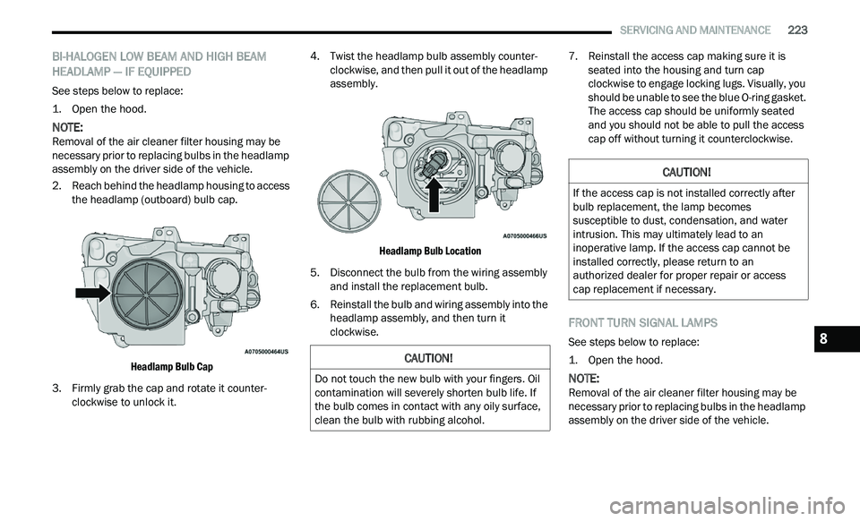
2. R each behind the headlamp housing to access
t
he headlamp (outboard) bulb cap.
Headlamp Bulb Cap
3. F irmly grab the cap and rotate it counter -
c
lockwise to unlock it. 4. Twist the headlamp bulb assembly counter
-
c
lockwise, and then pull it out of the headlamp
a s
sembly.
Headlamp Bulb Location
5. D isconnect the bulb from the wiring assembly
a
nd install the replacement bulb.
6. Reinstall the bulb and wiring assembly into the h
eadlamp assembly, and then turn it
clockwise. 7. Reinstall the access cap making sure it is
s
eated into the housing and turn cap
clockwise to engage locking lugs. Visually, you
should be unable to see the blue O-ring gasket.
The access cap should be uniformly seated
and you should not be able to pull the access
cap off without turning it counterclockwise.
FRONT TURN SIGNAL LAMPS
See steps below to replace:
1. O pen the hood.
NOTE:
Removal of the air cleaner filter housing may be
n e
cessary prior to replacing bulbs in the headlamp
assembly on the driver side of the vehicle.
CAUTION!
Do not touch the new bulb with your fingers. Oil
contamination will severely shorten bulb life. If
the bulb comes in contact with any oily surface,
clean the bulb with rubbing alcohol.
CAUTION!
If the access cap is not installed correctly after
bulb replacement, the lamp becomes
susceptible to dust, condensation, and water
intrusion. This may ultimately lead to an
inoperative lamp. If the access cap cannot be
installed correctly, please return to an
authorized dealer for proper repair or access
cap replacement if necessary.
8
Page 226 of 268

224 SERVICING AND MAINTENANCE
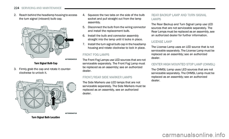
2. Reach behind the headlamp housing to access
the turn signal (inboard) bulb cap.
Turn Signal Bulb Cap
3. F irmly grab the cap and rotate it counter -
c
lockwise to unlock it.
Turn Signal Bulb Location
4. S
queeze the two tabs on the side of the bulb
s
ocket and pull straight out from the lamp
assembly.
5. D isconnect the bulb from the wiring connector
a
nd install the replacement bulb.
6. Install the bulb and connector assembly s
traight into the lamp until it locks in place.
7. Install the turn signal bulb cap in the headlamp h
ousing and rotate clockwise to lock in place.
FRONT FOG LAMPS
The Front Fog Lamps use LED sources that are not
serviceable separately. The Front Fog Lamp must
be replaced as an assembly; see an authorized
dealer.
FRONT/REAR SIDE MARKER LAMPS
The Side Markers use LED lamps that are not
serviceable separately. The Side Markers must be
replaced as an assembly, see an authorized
dealer.
REAR BACKUP LAMP AND TURN SIGNAL
LAMPS
The Rear Backup and Turn Signal Lamp use LED
sources that are not serviceable separately. The
Rear Lamps must be replaced as an assembly, see
an authorized dealer for further information.
LICENSE LAMP
The License Lamp uses an LED source that is not
serviceable separately. The License Lamp must be
replaced as an assembly; see an authorized
dealer.
CENTER HIGH MOUNTED STOP LAMP (CHMSL)
The CHMSL Lamp uses LED sources that are not
serviceable separately. The CHMSL Lamp must be
replaced as an assembly; see an authorized
dealer.
Page 264 of 268

262
Starting............................................................81Automatic Transmission..............................81Button.........................................................15Cold Weather..............................................83Engine Fails To Start...................................83Starting And Operating....................................81Starting Procedures.........................................81Steering...........................................................23Column Lock...............................................23Power..........................................................92Tilt Column...........................................23, 24Wheel, Heated.............................................24Wheel, Tilt............................................23, 24Storage..........................................................242Storage, Vehicle......................................50, 242Storing Your Vehicle......................................242Stuck, Freeing...............................................192Sun Roof..........................................................58Sunglasses Storage.........................................52Supplemental Restraint System – Air Bag.....159Synthetic Engine Oil.......................................203
T
Telescoping Steering Column...................23, 24Temperature Control, Automatic (ATC)............49Tilt Steering Column.................................23, 24Time Delay
Headlight.....................................................42Tire And Loading Information Placard...........229
Tire Markings................................................225Tire Safety Information.................................225Tires...................................177, 232, 236, 241Aging (Life Of Tires)..................................234Air Pressure..............................................232Chains......................................................239Changing.........................................182, 184Compact Spare.........................................236General Information........................232, 236High Speed...............................................233Inflation Pressure.....................................232Jacking.....................................................184Life Of Tires..............................................234Load Capacity...........................................229Pressure Monitoring System (TPMS)..76, 148Quality Grading.........................................241Radial.......................................................233Replacement............................................235Rotation....................................................240Safety..............................................225, 232Sizes.........................................................226Snow Tires................................................236Spare Tires.............................183, 236, 237Spinning...................................................234Trailer Towing...........................................117Tread Wear Indicators..............................234Wheel Nut Torque.....................................245To Open Hood..................................................59Tongue Weight/Trailer Weight......................116
Towing...........................................................114Behind A Motorhome................................119Disabled Vehicle.......................................193Guide........................................................116Recreational.............................................119Weight......................................................116Towing Behind A Motorhome........................119Traction.........................................................119Traction Control............................................142Trailer Towing................................................114Hitches.....................................................115Minimum Requirements...........................116Tips...........................................................118Trailer And Tongue Weight........................116Wiring.......................................................118Trailer Towing Guide.....................................116Trailer Weight................................................116Transfer CaseFluid.................................................213, 250Maintenance............................................213Transmission....................................................87Automatic..........................................87, 212Fluid..........................................................250Maintenance............................................212Shifting........................................................85Transporting Pets..........................................176Tread Wear Indicators...................................234Trunk Lid (Deck Lid).........................................60Trunk Release Remote Control........................60
Turn Signals..............................................43, 78