2021 ALFA ROMEO STELVIO power steering
[x] Cancel search: power steeringPage 90 of 280
STARTING AND OPERATING
88
After Starting — Warming Up The Engine
Proceed as follows:
Travel slowly, letting the engine run at a
reduced RPM, without accelerating
suddenly.
It is recommended to wait until the digital
engine coolant temperature indicator starts
to rise for maximum performance.
Stopping The Engine
To stop the engine, proceed as follows:
1. Park the vehicle in a position that is notdangerous for oncoming traffic.
2. Engage the PARK (P) mode.
3. With engine idling, push the ENGINE START/STOP button on the steering wheel
to STOP the engine.
NOTE:
Do not leave the ignition in ACC mode when
the engine is off.
To shut off the engine with vehicle speed
greater than 5 mph (8 km/h), you must push
and hold the ignition or push the ENGINE
START/STOP button three times consecutively
within a few seconds. The engine will shut
down, and the ignition will be placed in the
ACC mode With the keyless ignition system, it is possible
to exit the vehicle taking the key fob with you,
without the engine switching off. The vehicle
will inform about the absence of the key on
board, when the doors are closed.
After the engine has stopped (cycling from the
ACC to the OFF position) the accessories are
still powered for about three minutes, or until
a door is opened.
When the ignition is in the OFF mode, the
window switches remain active for three
minutes. Opening a front door will cancel this
function.
After severe driving, idle the engine to allow
the temperature inside the engine compart
-
ment to cool before shutting off the engine.
Turbocharger Cool Down
It is recommended before switching the
vehicle off, to keep the engine idling for a few
minutes so that the turbocharger can be suit -
ably lubricated. This procedure is particularly
recommended after severe driving.
After a full load operation, keep the engine
idling for three to five minutes before
switching it off.
This time allows the lubricating oil and the
engine coolant to eliminate the excessive heat
from combustion chamber, bearings, inner
components and turbocharger.
WARNING!
Never pour fuel or other flammable liquid
into the throttle body air inlet opening in
an attempt to start the vehicle. This could
result in flash fire causing serious
personal injury.
Do not attempt to push or tow your vehicle
to get it started. Vehicles equipped with an
automatic transmission cannot be started
this way. Unburned fuel could enter the
catalytic converter and once the engine
has started, ignite and damage the
converter and vehicle.
If the vehicle has a discharged battery,
booster cables may be used to obtain a
start from a booster battery or the battery
in another vehicle. This type of start can
be dangerous if done improperly
Ú
page 201.
CAUTION!
To prevent damage to the starter, do not
continuously crank the engine for more than
25 seconds at a time. Wait 60 seconds
before trying again.
21_GU_OM_EN_USC_t.book Page 88
Page 97 of 280
95
REVERSE (R)
Select this mode only with the vehicle at a
standstill.NEUTRAL (N)
Use this range when the vehicle is standing for
prolonged periods with the engine running.
The engine may be started in this range. Apply
the EPB and shift the transmission into PARK
(P) if you must leave the vehicle.
DRIVE (D)
Use this mode in normal driving conditions.
Shifting from DRIVE (D) to PARK (P) or REVERSE
(R) modes must take place only after releasing the
accelerator pedal, with vehicle at a standstill and
brake pedal pressed.
This mode ensures automatic engagement of the
most suitable gears for driving needs and
maximum fuel economy in terms of consumption.
In this position, the transmission shifts the gears
automatically, selecting the most suitable for
forward driving among those available as you go.
In this way the vehicle's optimal driving charac
-
teristics are provided for all conditions.
AutoStick
In the case of frequent shifting (e.g. for sport
driving, when the vehicle is driven with a heavy
load, on slopes, when towing heavy trailers), it is
recommended to use the AutoStick (sequential
shifting) mode to select and keep a lower fixed
ratio.
In these conditions, the use of a lower gear
improves vehicle performance and prevents over
-
heating.
It is possible to shift from DRIVE (D) mode to Auto -
Stick mode regardless of vehicle speed.
Activation
Starting from DRIVE (D) mode, to activate the
sequential drive mode, move the gear selector to
the left (– and + indication of the trim). The gear
engaged will be shown on the display.
Shifting is made by moving the gear selector
forward, toward symbol – or backward, toward
symbol +.
Steering Column Mounted Shift Paddles — If
Equipped
The gear can be manually shifted also by using
the paddles behind the steering wheel, pull
the right paddle (+) toward the steering wheel
and release it to engage a higher gear,
perform the same operation with the left
paddle (-) to engage a lower gear.
Never leave children alone in a vehicle, or
with access to an unlocked vehicle.
Allowing children to be in a vehicle unat -
tended is dangerous for a number of
reasons. A child or others could be seri -
ously or fatally injured. Children should be
warned not to touch the park brake, brake
pedal or the transmission gear selector.
Do not leave the key fob in or near the
vehicle (or in a location accessible to chil -
dren), and do not leave the ignition in the
ACC mode. A child could operate power
windows, other controls, or move the
vehicle.
CAUTION!
Before moving the transmission gear
selector out of PARK, you must push the
ignition button to cycle from OFF mode to
the ACC mode, and also press the brake
pedal. Otherwise, damage to the gear
selector could result.
DO NOT race the engine when shifting
from PARK or NEUTRAL into another gear
range, as this can damage the drivetrain.
WARNING! (Continued)
WARNING!
Do not coast in NEUTRAL and never turn off
the ignition to coast down a hill. These are
unsafe practices that limit your response to
changing traffic or road conditions. You
might lose control of the vehicle and have a
collision.
21_GU_OM_EN_USC_t.book Page 95
Page 103 of 280
101
"Natural" mode, depending on which mode
was selected before the engine was
stopped.
When the engine is started again, the
"RACE" mode selected previously is not
retained. The system will reactivate in
"Dynamic" mode.
ALFA ACTIVE SUSPENSION
(AAS) — IF EQUIPPED
The vehicle's electronic suspension manage-
ment system is aimed at optimizing the
vehicle's performance.
The system continuously monitors the
damping of the suspensions through the actu -
ator installed on each shock absorber. This
way, the calibration of the shock absorbers
can be adjusted to the conditions of the road
surface and to the dynamic conditions of the
vehicle, improving its comfort and road
holding.
The driver can choose, even while driving,
(only in “Dynamic” mode), between two types
of suspension calibration: a more sporty or a
more comfortable one.
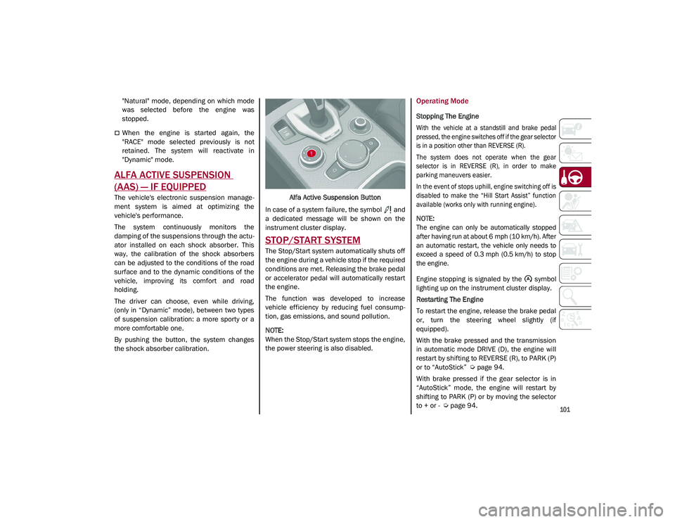
By pushing the button, the system changes
the shock absorber calibration. Alfa Active Suspension Button
In case of a system failure, the symbol and
a dedicated message will be shown on the
instrument cluster display.
STOP/START SYSTEM
The Stop/Start system automatically shuts off
the engine during a vehicle stop if the required
conditions are met. Releasing the brake pedal
or accelerator pedal will automatically restart
the engine.
The function was developed to increase
vehicle efficiency by reducing fuel consump -
tion, gas emissions, and sound pollution.
NOTE:
When the Stop/Start system stops the engine,
the power steering is also disabled.
Operating Mode
Stopping The Engine
With the vehicle at a standstill and brake pedal
pressed, the engine switches off if the gear selector
is in a position other than REVERSE (R).
The system does not operate when the gear
selector is in REVERSE (R), in order to make
parking maneuvers easier.
In the event of stops uphill, engine switching off is
disabled to make the “Hill Start Assist” function
available (works only with running engine).
NOTE:
The engine can only be automatically stopped
after having run at about 6 mph (10 km/h). After
an automatic restart, the vehicle only needs to
exceed a speed of 0.3 mph (0.5 km/h) to stop
the engine.
Engine stopping is signaled by the symbol
lighting up on the instrument cluster display.
Restarting The Engine
To restart the engine, release the brake pedal
or, turn the steering wheel slightly (if
equipped).
With the brake pressed and the transmission
in automatic mode DRIVE (D), the engine will
restart by shifting to REVERSE (R), to PARK (P)
or to “AutoStick”
Ú
page 94.
With brake pressed if the gear selector is in
“AutoStick” mode, the engine will restart by
shifting to PARK (P) or by moving the selector
to + or -
Ú
page 94.
21_GU_OM_EN_USC_t.book Page 101
Page 148 of 280
SAFETY
146
Given that, in a turn, the external wheels of the
car travel more than the internal ones and
therefore turn faster, sending a higher thrust
to the external rear wheel allows for the car to
be more stable and to not suffer an "under-
steer" condition. Understeer occurs when the
vehicle is turning less than appropriate for the
steering wheel position.
Dynamic Steering Torque (DST) System
DST uses the integration of the Electronic
Stability Control (ESC) system with the electric
power steering to increase the safety level of
the whole vehicle.
In critical situations (e.g. braking on surfaces
with different grip conditions), the ESC system
influences the steering through the DST func -
tion to implement an additional torque contri -
bution on the steering wheel in order to
suggest the most correct maneuver to the
driver.
The coordinated action of the brakes and
steering increases the safety and control of
the vehicle.
NOTE:
The DST feature is only meant to help the
driver realize the correct course of action
through small torques on the steering wheel,
which means the effectiveness of the DST
feature is highly dependent on the driver’s
sensitivity and overall reaction to the applied
torque. It is very important to realize that this feature will not steer the vehicle, meaning the
driver is still responsible for steering the
vehicle.
Drive Train Control (DTC) System
Some models of this vehicle are equipped with
an All-Wheel Drive (AWD) system, which offers
an optimal drive for countless driving condi
-
tions and road surfaces. The system reduces
tire slipping to a minimum, automatically
redistributing the torque to the front and rear
wheels as needed.
To maximize fuel savings, the vehicle with
AWD automatically passes to Rear-Wheel
Drive (RWD) when the road and environmental
conditions are such that they wouldn't cause
the tires to slip. When the road and environ -
mental conditions require better traction, the
vehicle automatically switches to AWD mode.
NOTE:
There may be a brief delay in shifting to
AWD mode after a tire slipping event occurs.
If the system failure symbol switches on,
after starting the engine or while driving, it
means that the AWD system is not working
properly. If the warning message activates
frequently, it is recommended to carry out
the maintenance operations.
Electronic Stability Control (ESC) System
The ESC system improves the directional
control and stability of the vehicle in various
driving conditions.
The ESC system corrects the vehicle’s under -
steer and oversteer, distributing the brake
force on the appropriate wheels. The torque
supplied by the engine can also be reduced in
order to maintain control of the vehicle.
The ESC system uses sensors installed on the
vehicle to determine the path that the driver
intends to follow and compares it with the
vehicle’s effective path. When the real path
deviates from the desired path, the ESC
system intervenes to counter the vehicle’s
oversteer or understeer.
Oversteer occurs when the vehicle is
turning more than it should according to the
angle of the steering wheel.
Understeer occurs when the vehicle is
turning less than it should according to the
angle of the steering wheel.
System Intervention
The intervention of the system is indicated by
the flashing of the ESC warning light on the
instrument panel, to inform the driver that the
vehicle stability and grip are critical.
21_GU_OM_EN_USC_t.book Page 146
Page 171 of 280
169
Supplemental Restraint Systems (SRS)
Some of the safety features described in this
section may be standard equipment on some
models, or may be optional equipment on
others. If you are not sure, ask an authorized
dealer.
The air bag system must be ready to protect
you in a collision. The Occupant Restraint
Controller (ORC) monitors the internal circuits
and interconnecting wiring associated with the
electrical Air Bag System Components. Your
vehicle may be equipped with the following Air
Bag System Components:
Air Bag System Components
Occupant Restraint Controller (ORC)
Air Bag Warning Light
Steering Wheel and Column
Instrument Panel
Knee Impact Bolsters
Driver and Front Passenger Air Bags
Seat Belt Buckle Switch
Supplemental Side Air Bags
Supplemental Knee Air Bags
Front and Side Impact Sensors
Seat Belt Pretensioners
Seat Track Position Sensors
Air Bag Warning Light
The Occupant Restraint Controller
(ORC) monitors the readiness of the
electronic parts of the air bag system
whenever the ignition switch is in the
START or ON/RUN position. If the ignition
switch is in the OFF position or in the ACC posi -
tion, the air bag system is not on and the air
bags will not inflate.
The ORC contains a backup power supply
system that may deploy the air bag system
even if the battery loses power or it becomes
disconnected prior to deployment.
The ORC turns on the Air Bag Warning Light in
the instrument panel for approximately four to
eight seconds for a self-check when the igni -
tion switch is first in the ON/RUN position.
After the self-check, the Air Bag Warning Light
will turn off. If the ORC detects a malfunction
in any part of the system, it turns on the Air
Bag Warning Light, either momentarily or continuously. A single chime will sound to alert
you if the light comes on again after initial
startup.
The ORC also includes diagnostics that will illu
-
minate the instrument panel Air Bag Warning
Light if a malfunction is detected that could
affect the air bag system. The diagnostics also
record the nature of the malfunction. While
the air bag system is designed to be mainte -
nance free, if any of the following occurs, have
an authorized dealer service the air bag
system immediately.The Air Bag Warning Light does not come on
during the four to eight seconds when the
ignition switch is first in the ON/RUN posi -
tion.
The Air Bag Warning Light remains on after
the four to eight-second interval.
The Air Bag Warning Light comes on inter-
mittently or remains on while driving.
NOTE:
If the speedometer, tachometer, or any engine
related gauges are not working, the Occupant
Restraint Controller (ORC) may also be
disabled. In this condition the air bags may not
be ready to inflate for your protection. Have an
authorized dealer service the air bag system
immediately.
Do not use the Automatic Locking Mode to
restrain occupants who are wearing the
seat belt or children who are using booster
seats. The locked mode is only used to
install rear-facing or forward-facing child
restraints that have a harness for
restraining the child.
WARNING! (Continued)
21_GU_OM_EN_USC_t.book Page 169
Page 177 of 280
175
If A Deployment Occurs
The front air bags are designed to deflate
immediately after deployment.
NOTE:
Front and/or side air bags will not deploy in all
collisions. This does not mean something is
wrong with the air bag system.
If you do have a collision which deploys the air
bags, any or all of the following may occur:
The air bag material may sometimes cause
abrasions and/or skin reddening to the
occupants as the air bags deploy and
unfold. The abrasions are similar to friction
rope burns or those you might get sliding
along a carpet or gymnasium floor. They are
not caused by contact with chemicals. They
are not permanent and normally heal
quickly. However, if you haven’t healed
significantly within a few days, or if you have
any blistering, see your doctor immediately.
As the air bags deflate, you may see some
smoke-like particles. The particles are a
normal by-product of the process that
generates the non-toxic gas used for air bag
inflation. These airborne particles may irri-
tate the skin, eyes, nose, or throat. If you
have skin or eye irritation, rinse the area
with cool water. For nose or throat irritation,
move to fresh air. If the irritation continues,
see your doctor. If these particles settle on
your clothing, follow the garment manufac -
turer’s instructions for cleaning. Do not drive your vehicle after the air bags
have deployed. If you are involved in another
collision, the air bags will not be in place to
protect you.
NOTE:
Air bag covers may not be obvious in the
interior trim, but they will open during air
bag deployment.
After any collision, the vehicle should be
taken to an authorized dealer immediately.
Enhanced Accident Response System
In the event of an impact, if the communica
-
tion network remains intact, and the power
remains intact, depending on the nature of the
event, the Occupant Restraint Controller (ORC)
will determine whether to have the Enhanced
Accident Response System perform the
following functions:
Cut off fuel to the engine (if equipped)
Cut off battery power to the electric motor (if
equipped)
Flash hazard lights as long as the battery
has power
Turn on the interior lights, which remain on
as long as the battery has power or for
15 minutes from the intervention of the
Enhanced Accident Response System
Unlock the power door locks
Your vehicle may also be designed to perform
any of these other functions in response to the
Enhanced Accident Response System:
Turn off the Fuel Filter Heater, Turn off the
HVAC Blower Motor, Close the HVAC Circula -
tion Door
Cut off battery power to the:
• Engine
• Electric Motor (if equipped)
• Electric power steering
• Brake booster
• Electric park brake
• Automatic transmission gear selector
• Horn
• Front wiper
• Headlamp washer pump
WARNING!
Deployed air bags and seat belt
pretensioners cannot protect you in another
collision. Have the air bags, seat belt
pretensioners, and the seat belt retractor
assemblies replaced by an authorized
dealer immediately. Also, have the
Occupant Restraint Controller System
serviced as well.
21_GU_OM_EN_USC_t.book Page 175
Page 203 of 280
201
11. Apply the adhesive label from the sealantbottle where it can be easily seen by the
driver as a reminder that the tire has been
treated with a Tire Service Kit, as well as
not to exceed the speed restriction for the
treated tire.
NOTE:
Only use original sealant cartridges, which can
be purchased at an authorized dealer.
Checking And Restoring Tire Pressure
The compressor can also be used to check
and, if necessary, restore the tire pressure.
Proceed as follows:
1. Make sure that the power switch is in the
O (off) position.
2. Connect the hose directly to the valve on the tire to be inflated.
3. Insert the plug into the socket in the passenger compartment or in the cargo
area and start the engine.
4. Start the compressor by putting the power switch to I (on). As soon as the correct
pressure is reached, put the power switch
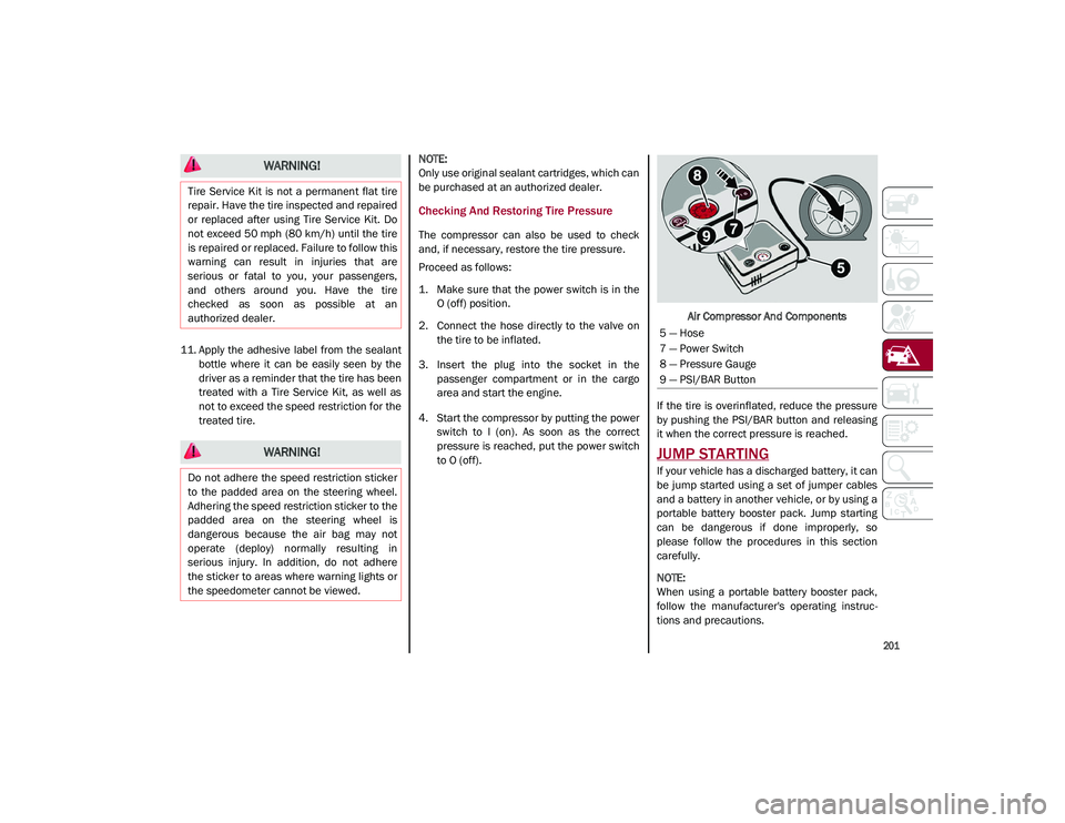
to O (off). Air Compressor And Components
If the tire is overinflated, reduce the pressure
by pushing the PSI/BAR button and releasing
it when the correct pressure is reached.
JUMP STARTING
If your vehicle has a discharged battery, it can
be jump started using a set of jumper cables
and a battery in another vehicle, or by using a
portable battery booster pack. Jump starting
can be dangerous if done improperly, so
please follow the procedures in this section
carefully.
NOTE:
When using a portable battery booster pack,
follow the manufacturer's operating instruc -
tions and precautions.
WARNING!
Tire Service Kit is not a permanent flat tire
repair. Have the tire inspected and repaired
or replaced after using Tire Service Kit. Do
not exceed 50 mph (80 km/h) until the tire
is repaired or replaced. Failure to follow this
warning can result in injuries that are
serious or fatal to you, your passengers,
and others around you. Have the tire
checked as soon as possible at an
authorized dealer.
WARNING!
Do not adhere the speed restriction sticker
to the padded area on the steering wheel.
Adhering the speed restriction sticker to the
padded area on the steering wheel is
dangerous because the air bag may not
operate (deploy) normally resulting in
serious injury. In addition, do not adhere
the sticker to areas where warning lights or
the speedometer cannot be viewed.
5 — Hose
7 — Power Switch
8 — Pressure Gauge
9 — PSI/BAR Button
21_GU_OM_EN_USC_t.book Page 201
Page 228 of 280
SERVICING AND MAINTENANCE
226
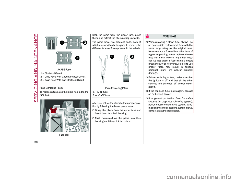
J-CASE Fuse
Fuse Extracting Pliers
To replace a fuse, use the pliers hooked to the
fuse box.
Fuse Box Grab the pliers from the upper tabs, press
them, and extract the pliers pulling upwards.
The pliers have two different ends, both of
which are specifically designed to remove the
different types of fuses present in the vehicle:
Fuse Extracting Pliers
After use, return the pliers to their proper posi -
tion by following the below procedures:
Grasp the pliers from the upper tabs and
insert them into their housing.
Push downward on the pliers into their
housing until they click into place.
1 — Electrical Circuit
2 — Case Fuse With Good Electrical Circuit
3 — Case Fuse With Bad Electrical Circuit
1 — MINI fuse
2 — J-CASE fuse
WARNING!
When replacing a blown fuse, always use
an appropriate replacement fuse with the
same amp rating as the original fuse.
Never replace a fuse with another fuse of
higher amp rating. Never replace a blown
fuse with metal wires or any other mate
-
rial. Do not place a fuse inside a circuit
breaker cavity or vice versa. Failure to use
proper fuses may result in serious
personal injury, fire and/or property
damage.
Before replacing a fuse, make sure that
the ignition is off and that all the other
services are switched off and/or disen -
gaged.
If the replaced fuse blows again, contact
an authorized dealer.
If a general protection fuse for safety
systems (air bag system, braking system),
power unit systems (engine system, trans -
mission system) or steering system blows,
contact an authorized dealer.
21_GU_OM_EN_USC_t.book Page 226