2021 ALFA ROMEO STELVIO ESP
[x] Cancel search: ESPPage 41 of 280
39
If the door mirrors were folded using the power
mirror control knob, they can only be returned
to the driving position by moving the knob to
the power folding position again.
NOTE:
The power folding operation can be enabled
only when the vehicle speed is lower than
31 mph (50 km/h).
Outside Automatic Dimming Mirrors — If
Equipped
The outside mirrors will automatically dim for
glare from vehicles behind you. This feature is
controlled by the inside automatic dimming
mirror. The mirrors will automatically adjust for
headlight glare when the inside mirror adjusts.
Heated Mirrors
Push the rear defrost button, located within
the climate controls, to activate the heated
mirrors.
UNIVERSAL GARAGE DOOR
OPENER (HOMELINK®)
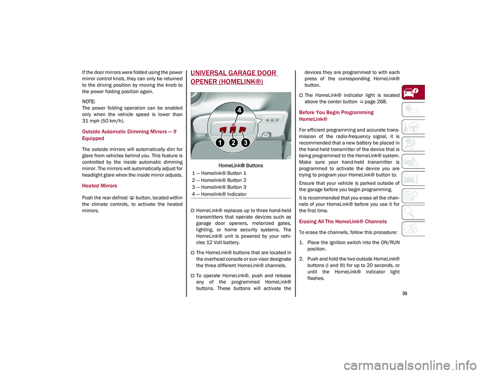
HomeLink® Buttons
HomeLink® replaces up to three hand-held
transmitters that operate devices such as
garage door openers, motorized gates,
lighting, or home security systems. The
HomeLink® unit is powered by your vehi-
cles 12 Volt battery.
The HomeLink® buttons that are located in
the overhead console or sun visor designate
the three different HomeLink® channels.
To operate HomeLink®, push and release
any of the programmed HomeLink®
buttons. These buttons will activate the devices they are programmed to with each
press of the corresponding HomeLink®
button.
The HomeLink® indicator light is located
above the center button
Ú
page 268.
Before You Begin Programming
HomeLink®
For efficient programming and accurate trans -
mission of the radio-frequency signal, it is
recommended that a new battery be placed in
the hand-held transmitter of the device that is
being programmed to the HomeLink® system.
Make sure your hand-held transmitter is
programmed to activate the device you are
trying to program your HomeLink® button to.
Ensure that your vehicle is parked outside of
the garage before you begin programming.
It is recommended that you erase all the chan -
nels of your HomeLink® before you use it for
the first time.
Erasing All The HomeLink® Channels
To erase the channels, follow this procedure:
1. Place the ignition switch into the ON/RUN position.
2. Push and hold the two outside HomeLink® buttons (I and III) for up to 20 seconds, or
until the HomeLink® indicator light
flashes.
1 — Homelink® Button 1
2 — Homelink® Button 2
3 — Homelink® Button 3
4 — Homelink® Indicator
21_GU_OM_EN_USC_t.book Page 39
Page 55 of 280
53
NOTE:
The MAX-DEF function remains active for
approximately three minutes once the engine
coolant reaches the proper temperature.
When the function is on, AUTO mode will deac-
tivate. The only manual operations possible
are adjusting blower speed and turning off the
Rear Window Defrost.
Pushing the button switches off the
MAX-DEF function.
Air Temperature Adjustment
Rotate the driver or passenger Temperature
Adjustment Knob clockwise for warmer
temperatures or counterclockwise for cooler
temperatures. The set temperatures are
shown on the radio system.
Push the SYNC button to sync the driver and
passenger air temperatures.
Rotate the passenger Temperature Adjust -
ment Knob to cancel the SYNC function. This
will set a new passenger side temperature.
Rotate the Temperature Adjustment Knob fully
clockwise to engage the HI (maximum heating)
setting or fully counterclockwise to engage the
LO (maximum cooling) setting. To deactivate
these functions, rotate the Temperature
Adjustment Knob to the desired temperature.
Rear passengers’ temperature is linked to
driver side selection.
AUTO Button
When the AUTO button is pushed (indicator
illuminated), the Climate Control system auto -
matically adjusts the following settings:
Quantity and distribution of air flow in the
passenger compartment
The air conditioner
Air recirculation
Cancels any manual settings
Selecting the AUTO function illuminates the
indicator on the A/C button.
If air distribution or the fan speed is manually
adjusted, the AUTO button indicator will turn
off to indicate that the Climate Control system
is no longer in AUTO mode.
After a manual adjustment, push the AUTO
button to resume the automatic system.
SYNC Button
Push the SYNC button (indicator illuminated)
to sync the passenger side air temperature
with the driver side air temperature.
This function makes temperature regulation
easier when the driver is traveling alone.
Turn the passenger Temperature Adjustment
Knob or push the passenger side Air Distribu-
tion Selection Button to change the passenger
side air temperature and return to separate air
temperature management.
Blower Speed
Turn the Blower Speed Knob to increase or
decrease the blower speed. The speed is
displayed with lighted indicators in the radio
system display.
Maximum fan speed = all indicators illumi -
nated on the radio system display
Minimum fan speed = one indicator illumi -
nated on the radio system display
The fan can be turned off by rotating the
Blower Speed Knob counterclockwise to the
off position (all segments on the radio system
display are turned off).
NOTE:
To restore automatic control of the fan speed,
push the AUTO button.
Air Distribution Selection
Push the Air Distribution Selection button on
the faceplate to change the mode of air distri -
bution.
NOTE:
In AUTO mode, the Climate Controls automati -
cally manage the air distribution. When set
manually, the respective symbols on the radio
system indicate the air distribution setting.
Panel Mode
Air comes from the outlets in the
instrument panel to ventilate the
chest and face. Each of these outlets
can be individually adjusted to direct
21_GU_OM_EN_USC_t.book Page 53
Page 78 of 280
GETTING TO KNOW YOUR INSTRUMENT PANEL
76
required. However, the conventional brake
system will continue to operate normally if the
brake indicator light is not on.
If the ABS light is on, the brake system should
be serviced as soon as possible to restore the
benefits of Anti-Lock Brakes. If the ABS light
does not turn on when the ignition is placed in
the ON/RUN position, have the light inspected
by an authorized dealer.
Electronic Stability Control (ESC) Indicator
Light — If Equipped
When the ignition is cycled to ON, the
indicator light illuminates, but
should turn off as soon as the engine
is started.
ESC System Intervention : Intervention by the
system is indicated by the flashing of the indi -
cator light: it indicates that the vehicle is in crit -
ical stability and grip conditions.
ESC System Failure : If the indicator light does
not turn off, or if it stays on with the engine
running, a failure was found in the ESC
system.
Hill Start Assist System Failure : The illumina-
tion of the indicator light indicates a Hill Start
Assist system failure.
In these cases, contact an authorized dealer
as soon as possible.
Electronic Stability Control (ESC) OFF
Indicator Light — If Equipped
When the ignition is cycled to ON, the
indicator light illuminates, but
should turn off as soon as the engine
is started.
The indicator light illuminates to indicate that
some active safety systems have been
partially or totally deactivated
Ú
page 145.
When the active safety systems are reacti -
vated, the indicator light turns off.
Tire Pressure Low Warning Light
The indicator light will illuminate to
indicate that the tire pressure is
lower than the recommended value
and/or that slow pressure loss is
occurring. In these cases, optimal tire duration
and fuel consumption may not be guaranteed.
In any situation in which the message on the
display is “See Manual”
Ú
page 161.
Tire Pressure Monitoring System (TPMS)
Warning Light
The warning light switches on and a
message is displayed to indicate
that the tire pressure is lower than
the recommended value and/or that
slow pressure loss is occurring. In these cases,
optimal tire duration and fuel consumption
may not be guaranteed. Should one or more tires be in the condition
mentioned above, the display will show the
indications corresponding to each tire.
Each tire, including the spare (if provided),
should be checked monthly when cold and
inflated to the inflation pressure recom
-
mended by the vehicle manufacturer on the
vehicle placard or tire inflation pressure label.
If your vehicle has tires of a different size than
the size indicated on the vehicle placard or tire
inflation pressure label, you should determine
the proper tire inflation pressure for those
tires.
As an added safety feature, your vehicle has
been equipped with a TPMS that illuminates a
low tire pressure telltale when one or more of
your tires is significantly underinflated. Accord -
ingly, when the low tire pressure telltale illumi -
nates, you should stop and check your tires as
soon as possible, and inflate them to the
proper pressure. Driving on a significantly
underinflated tire causes the tire to overheat
and can lead to tire failure. Under inflation
CAUTION!
Do not continue driving with one or more
flat tires as handling may be compromised.
Stop the vehicle, avoiding sharp braking
and steering. If a tire puncture occurs,
repair immediately using the dedicated tire
repair kit and contact an authorized dealer
as soon as possible.
21_GU_OM_EN_USC_t.book Page 76
Page 79 of 280
77
also reduces fuel efficiency and tire tread life,
and may affect the vehicle’s handling and
stopping ability.
Please note that the TPMS is not a substitute
for proper tire maintenance, and it is the
driver’s responsibility to maintain correct tire
pressure, even if under inflation has not
reached the level to trigger illumination of the
TPMS low tire pressure telltale.
Your vehicle has also been equipped with a
TPMS malfunction indicator to indicate when
the system is not operating properly. The
TPMS malfunction indicator is combined with
the low tire pressure telltale. When the system
detects a malfunction, the telltale will flash for
approximately one minute and then remain
continuously illuminated. This sequence will
continue upon subsequent vehicle start-ups
as long as the malfunction exists. When the
malfunction indicator is illuminated, the
system may not be able to detect or signal low
tire pressure as intended. TPMS malfunctions
may occur for a variety of reasons, including
the installation of replacement or alternate
tires or wheels on the vehicle that prevent the
TPMS from functioning properly. Always check
the TPMS malfunction telltale after replacing
one or more tires or wheels on your vehicle to
ensure that the replacement or alternate tires
and wheels allow the TPMS to continue to
function properly.
Rear Fog Lights
The indicator illuminates when the
rear fog light is activated.
Engine Check/Malfunction Indicator Light
(MIL)
In normal conditions, when the igni-
tion is cycled to ON, the indicator
light illuminates, but it should turn
off as soon as the engine is started.
The operation of the indicator light may be
checked by the traffic police using specific
devices. Comply with the laws and regulations
of the country where you are driving. Under these conditions, the vehicle can
continue traveling at moderate speed but
without demanding excessive effort from the
engine or high speed. Prolonged use of the
vehicle with the indicator light on constantly
may cause damage. Contact an authorized
dealer as soon as possible.
Forward Collision Warning (FCW) System
This indicator light informs the driver
that the frontal collision alarm func
-
tion is not enabled.
Drive carefully and contact an authorized
dealer as soon as possible.
Fuel Reserve/Limited Range
The indicator light (or the symbol in
the display) illuminates when about
2.4 gallons (9 liters) of fuel is left in
the tank.
WARNING!
The TPMS has been optimized for the
original equipment tires and wheels. TPMS
pressures and warning have been
established for the tire size equipped on
your vehicle. Undesirable system operation
or sensor damage may result when using
replacement equipment that is not of the
same size, type, and/or style. Aftermarket
wheels can cause sensor damage. Using
aftermarket tire sealants may cause the
Tire Pressure Monitoring System (TPMS)
sensor to become inoperable. After using
an aftermarket tire sealant it is
recommended that you take your vehicle to
an authorized dealership to have your
sensor function checked.
CAUTION!
If, turning the ignition device to ON, the
warning light does not turn on or if it
turns on steadily or flashing when traveling
(on some versions together with the
message on the display), contact an
authorized dealer as soon as possible.
21_GU_OM_EN_USC_t.book Page 77
Page 80 of 280
GETTING TO KNOW YOUR INSTRUMENT PANEL
78
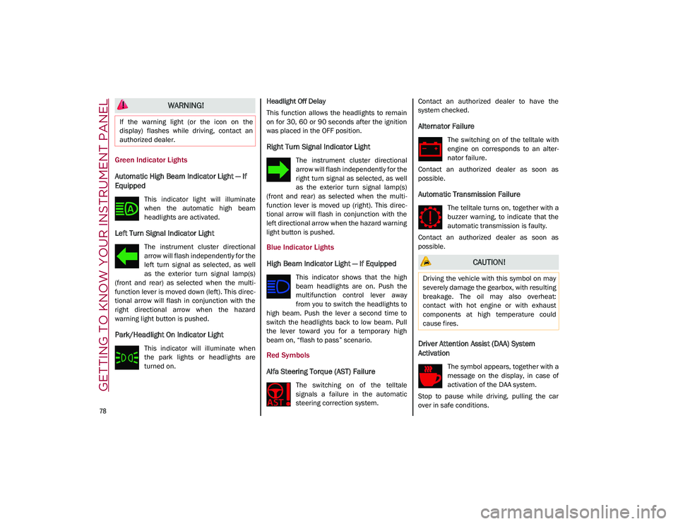
Green Indicator Lights
Automatic High Beam Indicator Light — If
Equipped
This indicator light will illuminate
when the automatic high beam
headlights are activated.
Left Turn Signal Indicator Light
The instrument cluster directional
arrow will flash independently for the
left turn signal as selected, as well
as the exterior turn signal lamp(s)
(front and rear) as selected when the multi -
function lever is moved down (left). This direc -
tional arrow will flash in conjunction with the
right directional arrow when the hazard
warning light button is pushed.
Park/Headlight On Indicator Light
This indicator will illuminate when
the park lights or headlights are
turned on. Headlight Off Delay
This function allows the headlights to remain
on for 30, 60 or 90 seconds after the ignition
was placed in the OFF position.
Right Turn Signal Indicator Light
The instrument cluster directional
arrow will flash independently for the
right turn signal as selected, as well
as the exterior turn signal lamp(s)
(front and rear) as selected when the multi -
function lever is moved up (right). This direc -
tional arrow will flash in conjunction with the
left directional arrow when the hazard warning
light button is pushed.
Blue Indicator Lights
High Beam Indicator Light — If Equipped
This indicator shows that the high
beam headlights are on. Push the
multifunction control lever away
from you to switch the headlights to
high beam. Push the lever a second time to
switch the headlights back to low beam. Pull
the lever toward you for a temporary high
beam on, “flash to pass” scenario.
Red Symbols
Alfa Steering Torque (AST) Failure
The switching on of the telltale
signals a failure in the automatic
steering correction system. Contact an authorized dealer to have the
system checked.
Alternator Failure
The switching on of the telltale with
engine on corresponds to an alter
-
nator failure.
Contact an authorized dealer as soon as
possible.
Automatic Transmission Failure
The telltale turns on, together with a
buzzer warning, to indicate that the
automatic transmission is faulty.
Contact an authorized dealer as soon as
possible.
Driver Attention Assist (DAA) System
Activation
The symbol appears, together with a
message on the display, in case of
activation of the DAA system.
Stop to pause while driving, pulling the car
over in safe conditions.
WARNING!
If the warning light (or the icon on the
display) flashes while driving, contact an
authorized dealer.
CAUTION!
Driving the vehicle with this symbol on may
severely damage the gearbox, with resulting
breakage. The oil may also overheat:
contact with hot engine or with exhaust
components at high temperature could
cause fires.
21_GU_OM_EN_USC_t.book Page 78
Page 89 of 280
87
How To Use Remote Start
All of the following conditions must be met
before the engine will remote start:
Gear selector in PARK (P).
Doors closed.
Hood closed.
Liftgate closed.
Hazard switch off.
Brake switch inactive (brake pedal not
pressed).
Battery at an acceptable charge level.
PANIC button not pushed.
System not disabled from previous remote
start event.
Vehicle Security System indicator flashing.
Ignition in the OFF mode (if equipped with
keyless ignition system).
Fuel level meets minimum requirement.
Remote Start Comfort Systems — If Equipped
When Remote Start is activated, the heated
steering wheel and driver heated seat features
will automatically turn on in cold weather.
These features will stay on through the dura -
tion of remote start until the ignition is placed
in the ON/RUN mode. Remote Start Windshield Wiper De–Icer Acti
-
vation — If Equipped
When remote start is active and the outside ambient
temperature is less than 39°F (4°C), the Windshield
Wiper De-Icer will be enabled. Exiting remote start will
resume previous operation, except if the Windshield
Wiper De-Icer is active.
The Windshield Wiper De-Icer timer and oper -
ation will continue.
Cold Weather Operation
To prevent possible engine damage while
starting at low temperatures, this vehicle will
inhibit engine cranking when the ambient
temperature is less than –22°F (–30°C) and
the oil temperature sensor reading indicates
an engine block heater has not been used. An
externally-powered electric engine block
heater is available as optional equipment or
from an authorized dealer.
The message “plug in engine heater” will be
displayed in the instrument cluster when the
ambient temperature is below 5°F (–15°C) at the
time the engine is shut off as a reminder to avoid
possible crank delays at the next cold start.
Extended Park Starting
If the vehicle has not been started or driven for
at least 30 days, it is advisable to follow the
indications below.
To start the engine, proceed as follows:
1. Briefly push the ignition button
2. If the engine does not start, wait five seconds and let the starter cool down and
then repeat the starting procedure
3. If the engine does not start after eight attempts, let the starter cool down for at
least 10 seconds, and then repeat the
starting procedure
If the problem persists, contact an authorized
dealer.
NOTE:
After prolonged vehicle inactivity, very difficult
starting, that can be noticed through rapid
fatigue of the starter, might also be due to a
partially drained battery
Ú
page 201.
If Engine Fails To Start
Starting the Engine with Key Fob Battery Run
Down or Drained
If the ignition does not respond when the
button is pushed, the key fob battery might be
run down or drained. Therefore, the system
does not detect the presence of the key fob in
the vehicle, and will display a dedicated
message
Ú
page 20. CAUTION!
Use of the recommended oil and adhering
to the prescribed oil change intervals is
important to prevent engine damage and
ensure satisfactory starting in cold
conditions.
21_GU_OM_EN_USC_t.book Page 87
Page 92 of 280
STARTING AND OPERATING
90
For the first 1,500 miles (2,414 km):
Do not participate in track events, sport
driving schools, or similar activities during
the first 1,500 miles (2,414 km).
NOTE:
Monitor engine oil with every refueling and add
if necessary. Oil and fuel consumption may be
higher through the first oil change interval.
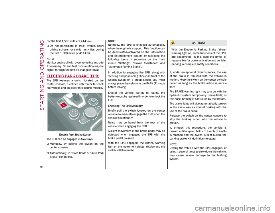
ELECTRIC PARK BRAKE (EPB)
The EPB features a switch located on the
center console, a caliper with motor for each
rear wheel, and an electronic control module.
Electric Park Brake Switch
The EPB can be engaged in two ways:
Manually, by pulling the switch on the
center console.
Automatically, in “Safe Hold” or “Auto Park
Brake” conditions.
NOTE:
Normally, the EPB is engaged automatically
when the engine is stopped. This function can
be deactivated/activated on the Information
and Entertainment system by selecting the
following items in sequence on the main
menu: “Settings”, “Driver Assistance” and
“Automatic Parking Brake”.
In addition to engaging the EPB, along with
steering and positioning chocks in front of the
wheels (when on a steep slope), you must
always place the vehicle in the PARK (P) mode
before leaving.
Should the vehicle battery be faulty, the
battery must be replaced in order to unlock the
EPB.
Engaging The EPB Manually
Briefly pull the switch located on the center
console to manually engage the EPB when the
vehicle is stationary.
Noise may be heard from the rear of the
vehicle when engaging the EPB.
A slight movement of the brake pedal may be
detected when engaging the EPB with the
brake pedal pressed.
With the EPB engaged, the BRAKE warning
light on the instrument cluster display and the
switch will illuminate.
If, under exceptional circumstances, the use
of the brake is required with the vehicle in
motion, keep the switch on the center console
pulled as long as the brake action is neces
-
sary.
The BRAKE warning light may turn on with the
hydraulic system temporarily unavailable; in
this case, braking is controlled by the motors.
The brake lights will also automatically turn on
in the same way as normal braking with the
use of the brake pedal.
Release the switch on the center console to
stop the braking action with the vehicle in
motion.
If, through this procedure, the vehicle is
braked until a speed below 1.9 mph (3 km/h)
is reached and the switch is kept pulled, the
parking brake will definitively engage.
NOTE:
Driving the vehicle with the EPB engaged, or
using it several times to slow down the vehicle,
may cause severe damage to the braking
system.
CAUTION!
With the Electronic Parking Brake failure
warning light on, some functions of the EPB
are deactivated. In this case the driver is
responsible for brake activation and vehicle
parking in complete safety conditions.
21_GU_OM_EN_USC_t.book Page 90
Page 95 of 280
93
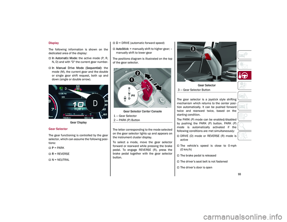
Display
The following information is shown on the
dedicated area of the display:
In Automatic Mode: the active mode (P, R,
N, D) and with "D" the current gear number.
In Manual Drive Mode (Sequential) : the
mode (M), the current gear and the double
or single gear shift request, both up and
down (single or double arrow).
Gear Display
Gear Selector
The gear functioning is controlled by the gear
selector, which can assume the following posi -
tions:
P = PARK
R = REVERSE
N = NEUTRAL
D = DRIVE (automatic forward speed)
AutoStick : + manually shift to higher gear; –
manually shift to lower gear
The positions diagram is illustrated on the top
of the gear selector.
Gear Selector Center Console
The letter corresponding to the mode selected
on the gear selector lights up and appears on
the instrument cluster display.
To select a mode, move the gear selector
forward or rearward while pressing the brake
pedal. To engage REVERSE (R), press the
brake pedal together with the gear selector
button. Gear Selector
The gear selector is a joystick style shifting
mechanism which returns to the center posi -
tion automatically. It can be pushed forward
twice and rearward twice, based on the
starting condition.
The PARK (P) mode can be enabled/disabled
by pushing the PARK (P) button. PARK (P)
mode is automatically activated if the
following conditions are met simultaneously:
DRIVE (D) mode or REVERSE (R) mode is
active
The vehicle’s speed is close to 0 mph
(0 km/h)
The brake pedal is released
The driver’s seat belt is not fastened
The driver’s door is open
1 — Gear Selector
2 — PARK (P) Button
3 — Gear Selector Button
21_GU_OM_EN_USC_t.book Page 93