2021 ALFA ROMEO STELVIO ESP
[x] Cancel search: ESPPage 209 of 280
207
ENHANCED ACCIDENT
RESPONSE SYSTEM (EARS)
This vehicle is equipped with an Enhanced
Accident Response System.
This feature is a communication network that
takes effect in the event of an impact
Ú
page 175.
EVENT DATA RECORDER (EDR)
This vehicle is equipped with an event data
recorder (EDR). The main purpose of an EDR is
to record data that will assist in understanding
how a vehicle’s systems performed under
certain crash or near crash-like situations,
such as an air bag deployment or hitting a road
obstacle
Ú
page 178.
Failure to follow proper tow eye usage may
cause components to break resulting in
serious injury or death.
CAUTION!
The tow eye must be used exclusively for
roadside assistance operations. Only use
the tow eye with an appropriate device in
accordance with the highway code (a rigid
bar or rope) to flat tow the vehicle for a
short distance to the nearest service loca -
tion.
Tow eyes MUST NOT be used to tow vehi -
cles off the road or where there are obsta -
cles.
In compliance with the above conditions,
towing with a tow eye must take place with
two vehicles (one towing, the other towed)
aligned as much as possible along the
same center line. Damage to your vehicle
may occur if these guidelines are not
followed.
When towing, only use a facility that can
tow vehicles with low ground clearances
as extensive damage can result by using a
standard tow truck platform.
WARNING! (Continued)
21_GU_OM_EN_USC_t.book Page 207
Page 217 of 280
215
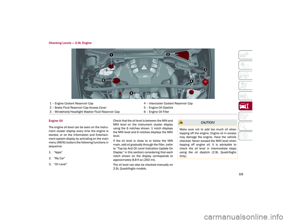
Checking Levels — 2.9L Engine
Engine Oil
The engine oil level can be seen on the instru-
ment cluster display every time the engine is
started, or on the Information and Entertain -
ment system display by activating on the main
menu (MENU button) the following functions in
sequence:
1. “Apps”
2. “My Car”
3. “Oil Level” Check that the oil level is between the MIN and
MAX level on the instrument cluster display
using the 6 notches shown. 1 notch displays
the MIN level and 6 notches displays the MAX
level.
If the oil level is close to or below the MIN
mark, add oil gradually through the filler, (refer
to “Top-Up And Oil Level Indication Update On
Display” in this section) considering that each
notch shown on the display corresponds to
approximately 8.8 fl oz (250 ml).
The oil level can also be checked manually on
2.9L Quadrifoglio models.
1 – Engine Coolant Reservoir Cap
4 – Intercooler Coolant Reservoir Cap
2 – Brake Fluid Reservoir Cap Access Cover 5 – Engine Oil Dipstick
3 – Windshield/Headlight Washer Fluid Reservoir Cap 6 – Engine Oil Filler
CAUTION!
Make sure not to add too much oil when
topping off the engine. Engine oil in excess
may damage the engine. Have the vehicle
checked. Never exceed the MAX level when
topping off engine oil. It is advisable to
check the oil level in intermediate steps
using the oil dipstick (2.9L Quadrifoglio
Only).
21_GU_OM_EN_USC_t.book Page 215
Page 229 of 280
227
Fuse Location
The fuses, which can be replaced by the user,
are grouped in two boxes below the passenger
side foot board and inside the luggage
compartment.
Control Unit Under Passenger Side
Footboard
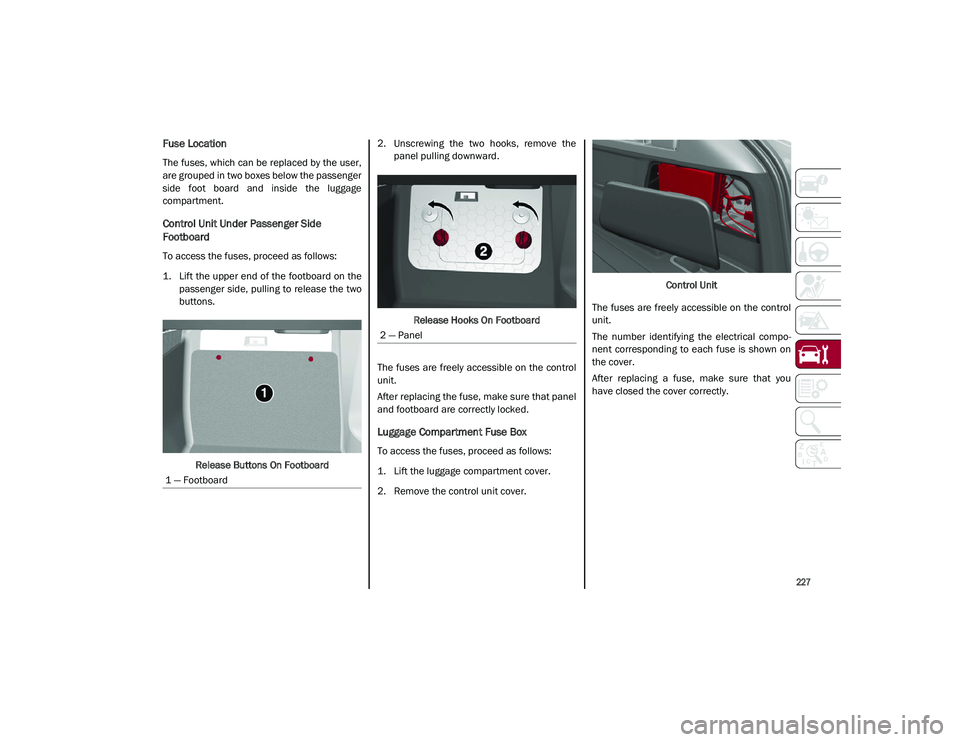
To access the fuses, proceed as follows:
1. Lift the upper end of the footboard on thepassenger side, pulling to release the two
buttons.
Release Buttons On Footboard 2. Unscrewing the two hooks, remove the
panel pulling downward.
Release Hooks On Footboard
The fuses are freely accessible on the control
unit.
After replacing the fuse, make sure that panel
and footboard are correctly locked.
Luggage Compartment Fuse Box
To access the fuses, proceed as follows:
1. Lift the luggage compartment cover.
2. Remove the control unit cover. Control Unit
The fuses are freely accessible on the control
unit.
The number identifying the electrical compo -
nent corresponding to each fuse is shown on
the cover.
After replacing a fuse, make sure that you
have closed the cover correctly.
1 — Footboard
2 — Panel
21_GU_OM_EN_USC_t.book Page 227
Page 231 of 280
229
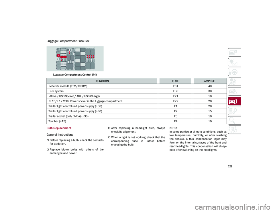
Luggage Compartment Fuse Box
Luggage Compartment Control Unit
Bulb Replacement
General Instructions
Before replacing a bulb, check the contacts
for oxidation.
Replace blown bulbs with others of the
same type and power.
After replacing a headlight bulb, always
check its alignment.
When a light is not working, check that the
corresponding fuse is intact before
changing the bulb.
NOTE:
In some particular climate conditions, such as
low temperature, humidity, or after washing
the vehicle, a thin condensation layer may
form on the internal surfaces of the front and
rear headlights. This condensation will disap
-
pear after switching on the headlights.
FUNCTIONFUSEAMPERE
Receiver module (TTM/TTEBM) F0140
Hi-Fi system F0830
I-Drive / USB Socket / AUX / USB Charger F2110
KL15/a 12 Volts Power socket in the luggage compartment F2220
Trailer light control unit power supply (+30) F120
Trailer light control unit power supply (+30) F215
Trailer socket (only EMEA) (+30) F310
Tow bar (+15) F410
21_GU_OM_EN_USC_t.book Page 229
Page 237 of 280
235
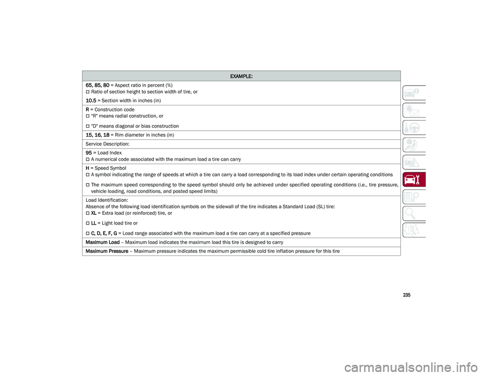
65, 85, 80 = Aspect ratio in percent (%)
Ratio of section height to section width of tire, or
10.5 = Section width in inches (in)
R = Construction code
"R" means radial construction, or
"D" means diagonal or bias construction
15, 16, 18 = Rim diameter in inches (in)
Service Description:
95 = Load Index
A numerical code associated with the maximum load a tire can carry
H = Speed Symbol
A symbol indicating the range of speeds at which a tire can carry a load corresponding to its load index under certain operating conditions
The maximum speed corresponding to the speed symbol should only be achieved under specified operating conditions (i.e., tire pressure,
vehicle loading, road conditions, and posted speed limits)
Load Identification:
Absence of the following load identification symbols on the sidewall of the tire indicates a Standard Load (SL) tire:
XL = Extra load (or reinforced) tire, or
LL = Light load tire or
C, D, E, F, G = Load range associated with the maximum load a tire can carry at a specified pressure
Maximum Load – Maximum load indicates the maximum load this tire is designed to carry
Maximum Pressure – Maximum pressure indicates the maximum permissible cold tire inflation pressure for this tire
EXAMPLE:
21_GU_OM_EN_USC_t.book Page 235
Page 242 of 280
SERVICING AND MAINTENANCE
240
Both underinflation and overinflation affect
the stability of the vehicle and can produce a
feeling of sluggish response or over respon-
siveness in the steering.
NOTE:
Unequal tire pressures from side to side
may cause erratic and unpredictable
steering response.
Unequal tire pressure from side to side may
cause the vehicle to drift left or right.
Fuel Economy
Underinflated tires will increase tire rolling
resistance resulting in higher fuel consump -
tion.
Tread Wear
Improper cold tire inflation pressures can
cause abnormal wear patterns and reduced
tread life, resulting in the need for earlier tire
replacement. Ride Comfort And Vehicle Stability
Proper tire inflation contributes to a comfort
-
able ride. Overinflation produces a jarring and
uncomfortable ride.
Tire Inflation Pressures
The proper cold tire inflation pressure is listed
on the driver's side B-pillar or rear edge of the
driver's side door.
At least once a month:
Check and adjust tire pressure with a good
quality pocket-type pressure gauge. Do not
make a visual judgement when determining
proper inflation. Tires may look properly
inflated even when they are underinflated.
Inspect tires for signs of tire wear or visible
damage.
Inflation pressures specified on the placard
are always “cold tire inflation pressure”. Cold
tire inflation pressure is defined as the tire
pressure after the vehicle has not been driven
for at least three hours, or driven less than
1 mile (1.6 km) after sitting for a minimum of
three hours. The cold tire inflation pressure must not exceed the maximum inflation pres
-
sure molded into the tire sidewall.
Check tire pressures more often if subject to a
wide range of outdoor temperatures, as tire
pressures vary with temperature changes.
Tire pressures change by approximately 1 psi
(7 kPa) per 12°F (7°C) of air temperature
change. Keep this in mind when checking tire
pressure inside a garage, especially in the
Winter.
Example: If garage temperature = 68°F
(20°C) and the outside temperature = 32°F
(0°C) then the cold tire inflation pressure
should be increased by 3 psi (21 kPa), which
equals 1 psi (7 kPa) for every 12°F (7°C) for
this outside temperature condition.
Tire pressure may increase from 2 to 6 psi
(13 to 40 kPa) during operation. DO NOT
reduce this normal pressure build up or your
tire pressure will be too low.
Tire Pressures For High Speed Operation
The manufacturer advocates driving at safe
speeds and within posted speed limits. Where
speed limits or conditions are such that the
vehicle can be driven at high speeds, main -
taining correct tire inflation pressure is very
important. Increased tire pressure and
reduced vehicle loading may be required for
high-speed vehicle operation. Refer to an
authorized tire dealer or original equipment
vehicle dealer for recommended safe oper -
ating speeds, loading and cold tire inflation
pressures.
Unequal tire pressures from one side of
the vehicle to the other can cause the
vehicle to drift to the right or left.
Always drive with each tire inflated to the
recommended cold tire inflation pressure.
WARNING! (Continued)
CAUTION!
After inspecting or adjusting the tire
pressure, always reinstall the valve stem
cap. This will prevent moisture and dirt from
entering the valve stem, which could
damage the valve stem.
21_GU_OM_EN_USC_t.book Page 240
Page 247 of 280
245
Compact Spare Tire — If Equipped
The compact spare is for temporary emer-
gency use only. You can identify if your vehicle
is equipped with a compact spare by looking at
the spare tire description on the Tire and
Loading Information Placard located on the
driver’s side door opening or on the sidewall of
the tire. Compact spare tire descriptions begin
with the letter “T” or “S” preceding the size
designation. Example: T145/80D18 103M.
T, S = Temporary Spare Tire
Since this tire has limited tread life, the orig -
inal equipment tire should be repaired (or
replaced) and reinstalled on your vehicle at
the first opportunity.
Do not install a wheel cover or attempt to
mount a conventional tire on the compact
spare wheel, since the wheel is designed
specifically for the compact spare tire. Do not
install more than one compact spare tire and
wheel on the vehicle at any given time.
Full Size Spare — If Equipped
The full size spare is for temporary emergency
use only. This tire may look like the originally
equipped tire on the front or rear axle of your
vehicle, but it is not. This spare tire may have
limited tread life. When the tread is worn to the
tread wear indicators, the temporary use full
size spare tire needs to be replaced. Since it is
not the same as your original equipment tire,
replace (or repair) the original equipment tire
and reinstall on the vehicle at the first oppor -
tunity.
Limited Use Spare — If Equipped
The limited use spare tire is for temporary
emergency use only. This tire is identified by a
label located on the limited use spare wheel.
This label contains the driving limitations for
this spare. This tire may look like the original
equipped tire on the front or rear axle of your
vehicle, but it is not. Installation of this limited
use spare tire affects vehicle handling. Since it
is not the same as your original equipment
tire, replace (or repair) the original equipment
tire and reinstall on the vehicle at the first
opportunity.
Wheel And Wheel Trim Care
All wheels and wheel trim, especially
aluminum and chrome plated wheels, should
be cleaned regularly using mild (neutral Ph)
soap and water to maintain their luster and to
prevent corrosion. Wash wheels with the same
soap solution recommended for the body of
the vehicle and remember to always wash
when the surfaces are not hot to the touch.
Your wheels are susceptible to deterioration
caused by salt, sodium chloride, magnesium
chloride, calcium chloride, etc., and other road
chemicals used to melt ice or control dust on
dirt roads. Use a soft cloth or sponge and mild
soap to wipe away promptly. Do not use harsh
chemicals or a stiff brush. They can damage
WARNING!
Compact and collapsible spares are for
temporary emergency use only. With these
spares, do not drive more than 50 mph
(80 km/h). Temporary use spares have
limited tread life. When the tread is worn to
the tread wear indicators, the temporary
use spare tire needs to be replaced. Be
sure to follow the warnings, which apply to
your spare. Failure to do so could result in
spare tire failure and loss of vehicle control.
WARNING!
Limited use spares are for emergency use
only. Installation of this limited use spare
tire affects vehicle handling. With this tire,
do not drive more than the speed listed on
the limited use spare wheel. Keep inflated
to the cold tire inflation pressures listed on
your Tire and Loading Information Placard
located on the driver’s side B-pillar or the
rear edge of the driver’s side door. Replace
(or repair) the original equipment tire at the
first opportunity and reinstall it on your
vehicle. Failure to do so could result in loss
of vehicle control.
21_GU_OM_EN_USC_t.book Page 245
Page 249 of 280

247
(Continued)
tires only in sets of four; failure to do so may
adversely affect the safety and handling of
your vehicle.
Snow tires generally have lower speed ratings
than what was originally equipped with your
vehicle and should not be operated at
sustained speeds over 75 mph (120 km/h).
For speeds above 75 mph (120 km/h) refer to
original equipment or an authorized tire dealer
for recommended safe operating speeds,
loading and cold tire inflation pressures.
While studded tires improve performance on
ice, skid and traction capability on wet or dry
surfaces may be poorer than that of
non-studded tires. Some states prohibit
studded tires; therefore, local laws should be
checked before using these tire types.
Tire Chains and Traction Devices
It is possible to fit 13 mm chains on all the
tires except for R20.
Use of traction devices require sufficient
tire-to-body clearance. Follow these recom-
mendations to guard against damage.
NOTE:
Traction device must be of proper size for
the tire, as recommended by the traction
device manufacturer.
Use on rear tires only.
Check the tension of the snow chains after
the first few meters have been driven.
Using snow chains with tires with non-orig -
inal dimensions may damage the vehicle.
Using different tires sizes or types (M+S,
snow, etc.) between the front and rear axles
may adversely affect vehicle driveability,
with the risk of losing control of the vehicle
and resulting accidents.
Tire Rotation Recommendations
Tires on the front and rear axles of vehicles
operate at different loads and perform
different steering, driving, and braking func -
tions. For these reasons, they wear at unequal
rates. These effects can be reduced by timely
rotation of tires. Rotation will increase tread
life, maintain traction levels and contribute to
a smooth, quiet ride.
To resolve this problem, tires should be
rotated at each service interval (approximately
every 10,000 miles [16,000 km]). More
frequent rotation is permissible if desired. The
reasons for any rapid or unusual wear should
be corrected prior to rotation being performed.
Tire Rotations Not Recommended — If
Equipped
Due to different size tires and wheels on front
and rear axles tire rotation is not possible for:
2.0T GME Engine equipped with a different
front and rear tire size.
CAUTION!
To avoid damage to your vehicle or tires,
observe the following precautions:
Because of restricted traction device
clearance between tires and other
suspension components, it is important
that only traction devices in good condi -
tion are used. Broken devices can cause
serious damage. Stop the vehicle immedi -
ately if noise occurs that could indicate
device breakage. Remove the damaged
parts of the device before further use.
Install device as tightly as possible and
then retighten after driving about ½ mile
(0.8 km).
Do not exceed 30 mph (48 km/h).
Drive cautiously and avoid severe turns
and large bumps, especially with a loaded
vehicle.
Do not drive for a prolonged period on dry
pavement.
Observe the traction device manufac -
turer’s instructions on the method of
installation, operating speed, and condi -
tions for use. Always use the suggested
operating speed of the device manufac -
turer’s if it is less than 30 mph (48 km/h).
Do not use traction devices on a compact
spare tire.
CAUTION! (Continued)
21_GU_OM_EN_USC_t.book Page 247