Page 81 of 553

GETTING TO KNOW YOUR VEHICLE79
Programming A Non-Rolling Code
For programming garage door openers manu -
factured before 1995.
1. Place the ignition in the ON/RUN position.
2. Place the hand-held transmitter 1 to 3 inches (3 to 8 cm) away from the Home-
Link® button you wish to program while
keeping the HomeLink® indicator light in
view.
3. Press and hold the HomeLink® button you want to program while you press and hold
the hand-held transmitter button.
4. Continue to hold both buttons and observe the indicator light. The HomeLink® indi-
cator will flash slowly and then rapidly after
HomeLink® has received the frequency
signal from the hand-held transmitter.
Release both buttons after the indicator
light changes from slow to rapid.
5. Press and hold the programmed Home -
Link® button and observe the indicator
light.
If the indicator light stays on constantly, programming is complete and the garage door/device should activate when the
HomeLink® button is pressed.
To program the two remaining Home
-
Link® buttons, repeat each step for each
remaining button. DO NOT erase the
channels.
Reprogramming A Single HomeLink® Button
(Non-Rolling Code)
To reprogram a channel that has been previ -
ously trained, follow these steps:
1. Place the ignition in the ON/RUN position.
2. Press and hold the desired HomeLink® button until the indicator light begins to
flash after 20 seconds. Do not release the
button.
3. Without releasing the button, proceed with “Programming A Non-Rolling Code” step 2
and follow all remaining steps.
Canadian/Gate Operator Programming
For programming transmitters in Canada/
United States that require the transmitter
signals to “time-out” after several seconds of
transmission. Canadian radio frequency laws require trans
-
mitter signals to time-out (or quit) after several
seconds of transmission – which may not be
long enough for HomeLink® to pick up the
signal during programming. Similar to this
Canadian law, some U.S. gate operators are
designed to time-out in the same manner.
It may be helpful to unplug the device during the
cycling process to prevent possible overheating
of the garage door or gate motor.
1. Place the ignition in the ON/RUN position.
2. Place the hand-held transmitter 1 to 3 inches (3 to 8 cm) away from the Home-
Link® button you wish to program while
keeping the HomeLink® indicator light in
view.
3. Continue to press and hold the HomeLink® button, while you press and release (cycle)
your hand-held transmitter every two
seconds until HomeLink® has successfully
accepted the frequency signal. The indi -
cator light will flash slowly and then rapidly
when fully trained.
2
20_DJD2_OM_EN_USC_t.book Page 79
Page 82 of 553

80GETTING TO KNOW YOUR VEHICLE
(Continued)
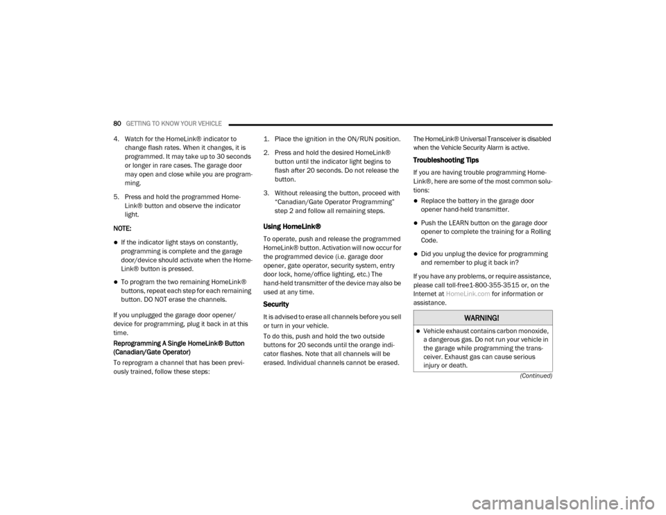
4. Watch for the HomeLink® indicator to change flash rates. When it changes, it is
programmed. It may take up to 30 seconds
or longer in rare cases. The garage door
may open and close while you are program -
ming.
5. Press and hold the programmed Home -
Link® button and observe the indicator
light.
NOTE:
If the indicator light stays on constantly,
programming is complete and the garage
door/device should activate when the Home -
Link® button is pressed.
To program the two remaining HomeLink®
buttons, repeat each step for each remaining
button. DO NOT erase the channels.
If you unplugged the garage door opener/
device for programming, plug it back in at this
time.
Reprogramming A Single HomeLink® Button
(Canadian/Gate Operator)
To reprogram a channel that has been previ -
ously trained, follow these steps:
1. Place the ignition in the ON/RUN position.
2. Press and hold the desired HomeLink®
button until the indicator light begins to
flash after 20 seconds. Do not release the
button.
3. Without releasing the button, proceed with “Canadian/Gate Operator Programming”
step 2 and follow all remaining steps.
Using HomeLink®
To operate, push and release the programmed
HomeLink® button. Activation will now occur for
the programmed device (i.e. garage door
opener, gate operator, security system, entry
door lock, home/office lighting, etc.) The
hand-held transmitter of the device may also be
used at any time.
Security
It is advised to erase all channels before you sell
or turn in your vehicle.
To do this, push and hold the two outside
buttons for 20 seconds until the orange indi -
cator flashes. Note that all channels will be
erased. Individual channels cannot be erased. The HomeLink® Universal Transceiver is disabled
when the Vehicle Security Alarm is active.
Troubleshooting Tips
If you are having trouble programming Home
-
Link®, here are some of the most common solu -
tions:
Replace the battery in the garage door
opener hand-held transmitter.
Push the LEARN button on the garage door
opener to complete the training for a Rolling
Code.
Did you unplug the device for programming
and remember to plug it back in?
If you have any problems, or require assistance,
please call toll-free1-800-355-3515 or, on the
Internet at HomeLink.com for information or
assistance.
WARNING!
Vehicle exhaust contains carbon monoxide,
a dangerous gas. Do not run your vehicle in
the garage while programming the trans -
ceiver. Exhaust gas can cause serious
injury or death.
20_DJD2_OM_EN_USC_t.book Page 80
Page 83 of 553

GETTING TO KNOW YOUR VEHICLE81
General Information
The following regulatory statement applies to all
Radio Frequency (RF) devices equipped in this
vehicle:
This device complies with Part 15 of the FCC
Rules and with Innovation, Science and
Economic Development Canada license-exempt
RSS standard(s). Operation is subject to the
following two conditions:
1. This device may not cause harmful interfer
-
ence, and
2. This device must accept any interference received, including interference that may
cause undesired operation.
Le présent appareil est conforme aux CNR
d`Innovation, Science and Economic Develop -
ment applicables aux appareils radio exempts
de licence. L'exploitation est autorisée aux deux
conditions suivantes:
1. l'appareil ne doit pas produire de brouil -
lage, et
2. l'utilisateur de l'appareil doit accepter tout brouillage radioélectrique subi, même si le
brouillage est susceptible d'en comprom -
ettre le fonctionnement. La operación de este equipo está sujeta a las
siguientes dos condiciones:
1. es posible que este equipo o dispositivo no
cause interferencia perjudicial y
2. este equipo o dispositivo debe aceptar cual -
quier interferencia, incluyendo la que
pueda causar su operación no deseada.
NOTE:
Changes or modifications not expressly
approved by the party responsible for compli -
ance could void the user’s authority to operate
the equipment.
Your motorized door or gate will open and
close while you are programming the
universal transceiver. Do not program the
transceiver if people, pets or other objects
are in the path of the door or gate. Only use
this transceiver with a garage door opener
that has a “stop and reverse” feature as
required by Federal safety standards. This
includes most garage door opener models
manufactured after 1982. Do not use a
garage door opener without these safety
features.
WARNING! (Continued)
2
20_DJD2_OM_EN_USC_t.book Page 81
Page 84 of 553

82GETTING TO KNOW YOUR VEHICLE
INTERNAL EQUIPMENT
Storage
Glove Compartment
The glove compartment is located on the
passenger side of the instrument panel and
features both an upper and lower storage area.
NOTE:
Not all vehicles are equipped with a door over
the upper storage area.
Glove Compartment
If equipped with a covered upper glove compart
-
ment, push the release button to open.
To open the lower glove compartment, pull the
release handle.Door Storage
Front Door Storage — If Equipped
Storage areas and bottle holders (driver’s side
only) are located in the door trim panels.
Front Door Storage
Rear Door Storage — If Equipped
Storage compartments are located in both the
driver and passenger rear door trim panels.
Rear Door Storage
Center Storage Compartment — If Equipped
The center storage compartment is located
between the driver and passenger seats. The
storage compartment provides an armrest and
contains both an upper and lower storage area.
Center Storage Compartment
1 — Upper Glove Compartment Release Button (If
Equipped)
2 — Upper Glove Compartment
3 — Lower Glove Compartment
20_DJD2_OM_EN_USC_t.book Page 82
Page 85 of 553

GETTING TO KNOW YOUR VEHICLE83
Pull on the upper handle on the front of the
armrest to raise the cover. The upper storage
area contains a USB power outlet located at the
rear of the area that can be used to power small
electrical devices, refer to “Electrical Power
Outlets” in this section for further information.
With the upper lid closed, pull on the lower
handle to open the lower storage bin. The lower
bin contains a power inverter outlet located in
the forward portion of the lower bin. There is
also a “fill line” located along the rear inside
wall of the lower bin. Contents above the “fill
line” may interfere with cupholder placement if
equipped with a premium center console.
Forward Portion Of Lower Storage Bin
Premium Center Console — If Equipped
The premium center console is equipped with
two front storage bins located in front of the
center storage compartment. These storage
bins may be equipped with tandem doors. Push
the front bin to access the cupholders. Or push
the rear bin to access the coinholder/small
storage bin.
Center Console Tandem Doors— If Equipped
Tandem Doors Open Position
WARNING!
This armrest is not a seat. Anyone seated
on the armrest could be seriously injured
during vehicle operation, or a collision. Only
use the center seating position when the
armrest is fully upright.
In a collision, the latch may open if the total
weight of the items stored exceeds about
10 lbs (4.5 kg). These items could be
thrown about endangering occupants of
the vehicle. Items stored should not exceed
a total of 10 lbs (4.5 kg).
WARNING!
Do not operate this vehicle with a console
compartment lid in the open position. Driving
with the console compartment lid open may
result in injury in a collision.
1 — Push Front Bin Access
2 — Push Rear Bin Access
1 — Front Bin Open
2 — Rear Bin Open
2
20_DJD2_OM_EN_USC_t.book Page 83
Page 86 of 553
84GETTING TO KNOW YOUR VEHICLE
Push the release button at the front of the
cupholder bin to slide tray rearward for access
of front lower storage bin, or forward to access
the rear lower storage bin with the center
console lid in the open position.
Push Release Button To Slide Tray
Front Bench Seat Storage — If Equipped
If your vehicle is equipped with a front bench
seat, storage can be found by folding down the
center seat back. A console storage area and
cupholders are available. With the seatback in
the upright position, lifting the seat bottom also
reveals a storage location.
Front Bench Seat Storage Location
There is a storage drawer located in the lower
center of the instrument panel. It can be
released by pushing the access button above it.
The drawer is actuator assisted once the access
button is pushed. Pull the drawer outward to the
fully open position.
Storage Drawer
1 — Access Button
2 — Storage Drawer
20_DJD2_OM_EN_USC_t.book Page 84
Page 87 of 553
GETTING TO KNOW YOUR VEHICLE85
Seatback Storage
Located in the back of both the driver and
passenger front seats are pockets that can be
used for storage.
Driver’s Side Seatback Storage
Second Row In-Floor Storage Bin — If
Equipped
In-floor storage bins are located in front of the
second row seats and can be used for extra
storage. The storage bins have removable liners
that can be easily removed for cleaning.
In-Floor Storage Bin And Latch
To open in-floor storage bin, remove the floor
mat (if equipped), and lift upward on the handle
of the latch and open the lid.
NOTE:
The front seat may have to be moved forward to
fully open the lid.
Opened Storage Bin
2
20_DJD2_OM_EN_USC_t.book Page 85
Page 88 of 553

86GETTING TO KNOW YOUR VEHICLE
Storage Bin (Regular Cab)
The storage bin is located behind the front
seats and runs the length of the cab.
Storage Bin
Fold Flat Load Floor — If Equipped
Crew Cab models with a 60/40 rear seat may
be equipped with a folding load floor. Unfolding The Load Floor/Crew Cab
1. Lift the 60/40 seat cushion(s) to the
upward position.
Load Floor Legs In Stowed Position
2. Unfold both the legs using the straps.
Load Floor Legs In Opened Position
3. Lift the front panel until the load floor
unfolds into position.
Load Floor In Open Position
4. Reverse the procedure to store the load floor.
Positioning The Load Floor For Storage Access
Under The Seat
1. Lift the 60/40 seat cushion(s) to the upward position.
2. Unsnap the securing snap located at either side of the load floor.
WARNING!
Do not operate the vehicle with loose items
stored on the load floor. While driving or in an
accident you may experience abrupt stopping,
rapid acceleration, or sharp turns. Loose
objects stored on the load floor may move
around with force and strike occupants,
resulting in serious or fatal injury.
20_DJD2_OM_EN_USC_t.book Page 86