2020 PEUGEOT PARTNER TEPEE ECU
[x] Cancel search: ECUPage 102 of 216

100
Remove and stow the head restraint
before installing a child seat with backrest
on a passenger seat.
Refit the head restraint once the child seat
has been removed.
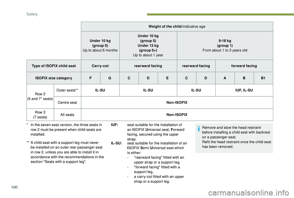
Weight of the child
/indicative age
Under 10
kg
(group 0)
Up to about 6
months
Under 10
kg
(group 0)
Under 13
kg
(group 0+)
Up to about 1 year 9 -18
kg
(g ro up 1)
From about 1 to 3 years old
Type of ISOFIX child seat Carr y- cotrearward facing rearward facing forward facing
ISOFIX size categor y F G C D E C D A B B1
Row 2
(5 and 7* seats) Outer seats**
IL- SU IL- SUIL- SUI U F, I L - S U
Centre seat Non-ISOFIX
Row 3
(7 seats) All seats
Non-ISOFIX
*
I
n the seven-seat version, the three seats in
row 2
must be present when child seats are
installed.
**
A c
hild seat with a support leg must never
be installed on an outer rear passenger seat
in row 2, unless you are able to install it in
accordance with the recommendations in the
section "Seats with a support leg". I UF:
seat suitable for the installation of
an ISOFIX U niversal seat, F or ward
facing, secured using the upper
strap.
IL- SU: seat suitable for the installation of an
ISOFIX S emi-Universal seat which
is either:
-
"
rear ward facing" fitted with an
upper strap or a support leg,
-
"
for ward facing" fitted with a
support leg,
-
a c
arry-cot fitted with an upper
strap or a support leg.
Safety
Page 103 of 216

101
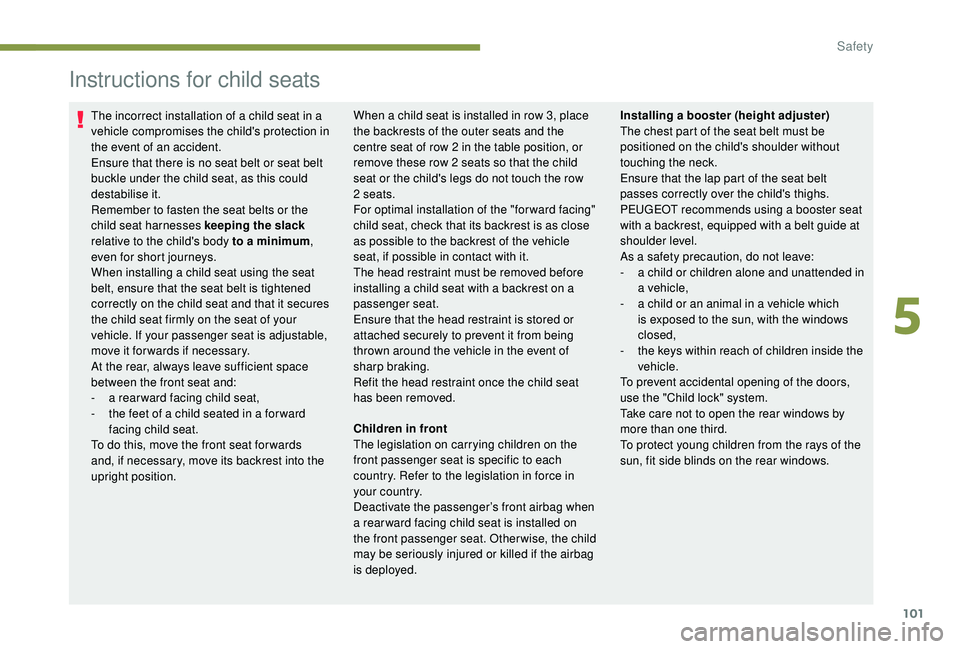
Instructions for child seats
The incorrect installation of a child seat in a
vehicle compromises the child's protection in
the event of an accident.
Ensure that there is no seat belt or seat belt
buckle under the child seat, as this could
destabilise it.
Remember to fasten the seat belts or the
child seat harnesses keeping the slack
relative to the child's body to a minimum,
even for short journeys.
When installing a child seat using the seat
belt, ensure that the seat belt is tightened
correctly on the child seat and that it secures
the child seat firmly on the seat of your
vehicle. If your passenger seat is adjustable,
move it for wards if necessary.
At the rear, always leave sufficient space
between the front seat and:
-
a r
ear ward facing child seat,
-
t
he feet of a child seated in a for ward
facing child seat.
To do this, move the front seat for wards
and, if necessary, move its backrest into the
upright position. When a child seat is installed in row 3, place
the backrests of the outer seats and the
centre seat of row 2 in the table position, or
remove these row 2 seats so that the child
seat or the child's legs do not touch the row
2 seats.
For optimal installation of the "forward facing"
child seat, check that its backrest is as close
as possible to the backrest of the vehicle
seat, if possible in contact with it.
The head restraint must be removed before
installing a child seat with a backrest on a
passenger seat.
Ensure that the head restraint is stored or
attached securely to prevent it from being
thrown around the vehicle in the event of
sharp braking.
Refit the head restraint once the child seat
has been removed.
Installing a booster (height adjuster)
The chest part of the seat belt must be
positioned on the child's shoulder without
touching the neck.
Ensure that the lap part of the seat belt
passes correctly over the child's thighs.
PEUGEOT recommends using a booster seat
with a backrest, equipped with a belt guide at
shoulder level.
As a safety precaution, do not leave:
-
a c
hild or children alone and unattended in
a vehicle,
-
a c
hild or an animal in a vehicle which
is exposed to the sun, with the windows
closed,
-
t
he keys within reach of children inside the
vehicle.
To prevent accidental opening of the doors,
use the "Child lock" system.
Take care not to open the rear windows by
more than one third.
To protect young children from the rays of the
sun, fit side blinds on the rear windows.
Children in front
The legislation on carrying children on the
front passenger seat is specific to each
country. Refer to the legislation in force in
your country.
Deactivate the passenger’s front airbag when
a rear ward facing child seat is installed on
the front passenger seat. Otherwise, the child
may be seriously injured or killed if the airbag
is deployed.
5
Safety
Page 107 of 216

105
Electronic engine
immobiliser
All of the keys contain an electronic immobiliser
device.
This device locks the engine supply system.
It is activated automatically when the key is
removed from the ignition.
When the ignition switch is turned on, a
dialogue is set up between the key and the
electronic immobiliser.
The metal part of the key must be correctly
unfolded to ensure a good connection.
In case of lost keys
See a PEUGEOT dealer with the vehicle
registration certificate and your ID.
A PEUGEOT dealer can retrieve the key
code and the transponder code to order the
replacement key.
When you leave the vehicle, check that the
lamps are off and do not leave valuables
visible.
As a safety precaution (with children on
board), remove the key from the ignition when
leaving the vehicle, even for a short time.
Parking brake
Application
F Pull the parking brake lever up to immobilise your vehicle.
F
C
heck that the parking brake is applied
firmly before leaving the vehicle.
When parking on a slope, turn your
wheels towards the kerb and pull the
parking brake lever up.
There is no advantage in engaging a gear
after parking the vehicle, particularly if the
vehicle is loaded. Apply the parking brake only when the
vehicle is stationary
.
In the exceptional case of use of the
parking brake when the vehicle is moving,
apply the brake by pulling gently to avoid
locking the rear wheels (risk of skidding).
Release
F Pull the lever up slightly and press the button to release the parking brake lever.
When the vehicle is being driven, this
warning lamp coming on indicates
that the parking brake is still on or
has not been fully released.
Manual gearbox
To change gear easily, always press the clutch
pedal fully.
To prevent the mat from becoming caught
under the pedal:
-
e
nsure that the mat is positioned and
secured to the floor correctly,
-
n
ever fit one mat on top of another.
When driving, avoid leaving your hand on the
gear knob as the force exerted, even if slight,
may wear the internal components of the
gearbox over time.
6
Driving
Page 119 of 216

117
Pressing the accelerator pedal in order to
exceed the programmed speed will have
no effect unless you press the pedal firmly
beyond the point of resistance .
The speed limiter is deactivated temporarily
and the programmed speed setting flashes,
accompanied by an audible signal.
To return to the limiter function, reduce your
speed below the programmed speed.
Flashing of the speed setting
It flashes:
- a fter forcing the accelerator pedal past the
point of resistance,
-
w
hen the limiter cannot prevent the speed
of the vehicle increasing, because of the
profile of the road or when going down a
steep hill,
-
u
nder sharp acceleration.
Switching the funtion off
F Place the knob at the 0 position or switch off the ignition to switch the function off.
The last programmed speed remains in the
memory.
Operating fault
The programmed speed is cleared, then
replaced by three dashes.
Contact a PEUGEOT dealer or a qualified
workshop to have the system checked.
Under no circumstances can the speed
limiter replace the need to obser ve speed
limits, nor can it replace the need for
vigilance on the part of the driver.
Always pay attention to the profile of the
road and sharp acceleration and stay in
complete control of your vehicle.
To avoid any jamming under the pedals:
-
e
nsure that the mat is positioned and
secured to the floor correctly,
-
n
ever fit one mat on top of another.
"CRUISE" cruise control
System which automatically
maintains the speed of the vehicle
at the value programmed by the
driver, without any action on the
accelerator pedal.
1. Cruise control mode Selection/Off.
2. Decreases the set value.
3. Increases the set value.
4. Stop/Resume cruise control.
To be programmed or activated, the vehicle
speed must be above 25
mph (40 km/h), with at
least the 4
th gear engaged.
The cruise control selection status and the
programmed speed are displayed in the control
panel.
6
Driving
Page 122 of 216

120
When changing the programmed
reference speed by means of a maintained
press, remain vigilant as the speed can
increase or decrease rapidly.
Do not use the cruise control on slippery
roads or in heavy traffic.
When descending a steep hill, the cruise
control system cannot prevent the vehicle
from exceeding the programmed speed.
The cruise control system cannot in
any circumstances replace the need
to obser ve speed limits or the need for
vigilance on the part of the driver.
It is advisable to leave your feet near the
pedals.
To avoid any jamming under the pedals:
-
e
nsure that the mat is positioned and
secured to the floor correctly,
-
n
ever fit one mat on top of another.
Active City Brake
Active City Brake is a driving assistance
system that aims to avoid a frontal collision
or reduce the speed of an impact if the driver
does not react sufficiently (inadequate brake
application). This system has been designed to
improve driving safety.
The driver must always check the traffic
and assess the distance and relative
speed of other vehicles.
Active City Brake cannot in any
circumstances replace the need for
vigilance on the part of the driver.
Never look at the laser sensor through
an optical instrument (magnifying glass,
microscope, etc.) at a distance of less
than 10
centimetres: risk of eye injury!
Principle
Using a laser sensor located at the top of the
windscreen, this system detects a vehicle
running in the same direction or stationary
ahead of your vehicle.Automatic braking occurs later than if
done by the driver, so as to inter vene only
when there is a high risk of collision.
Conditions of activation
Active City Brake functions if the following
conditions are met:
-
t
he ignition is on,
-
t
he vehicle is moving for ward,
-
t
he speed is between 3 and 19 mph (5 and
30
km/h),
-
t
he braking assistance systems (ABS,
EBFD, EBA) have not failed,
-
t
he trajectory control systems (ASR, DSC)
are not deactivated or faulty,
-
t
he vehicle is not making a sharp turn,
-
t
he system has not triggered in the last ten
seconds.
If necessary, the vehicle's braking system is
operated automatically to avoid a collision with
the vehicle ahead.
Driving
Page 136 of 216

134
F Open the protective covers.
F U nscrew the 4 screws using the spanner
and remove them.
F
T
urn the bars by 90°, positioning the hollow
parts towards the front.
F
R
efit the 4 screws and tighten them using
the spanner.
F
C
lose the protective covers.
Maximum weights on bars
F Only use the strap passages A to secure the load correctly. In all cases, the load must rest on the non-slip
bands provided for this purpose, and must not
touch the roof or the glazing on the roof.
-
T
ransverse bars on longitudinal bars: 75 kg
(these bars are not compatible with the
Zenith).
-
R
oof rack: 120 kg.
-
T
ransverse bars on roof: 100 kg.
-
T
ransverse bars on longitudinal bars: 75
kg.
Other accessories
These accessories and parts, having been
tested and approved for reliability and safety,
are all adapted to your vehicle. A wide range of
genuine parts is available.
Another range of accessories is also available
which is centred around comfort, leisure and
maintenance:
Anti-intrusion alarm, glass engraving, first aid
kit, safety vest, front and rear parking sensors,
hazard warning triangle, alloy wheel anti-theft
bolts, etc.
Seat covers compatible with airbags for front
seat, bench seat, rubber mats, carpet mats,
snow chains, blinds, tailgate bicycle carrier, etc.
To avoid any jamming under the pedals:
-
e
nsure that the mat and its fixings are
positioned correctly,
-
n
ever fit one mat on top of another.
Recommendations for
loading the roof
This procedure requires the use of the spanner
supplied with the tools for changing a wheel.For more information on Changing a
wheel , refer to the corresponding section.
Audio systems, hands-free kit, speakers, CD
changer, navigation, USB Box, Video Kit, etc.
With a wide range of audio and telematic
equipment offered on the market, the technical
constraints associated with the installation of
devices from these product families require
Practical information
Page 137 of 216

135
taking into account the device specifics and
their compatibility with the capacities of the
standard equipment of your vehicle. Please
check this with a PEUGEOT dealer in advance.
The spare parts department publishes a
catalogue of accessories offering various
equipment and fittings, such as:
Load stops (all types).
Loading roller.
Towbar, towing harness: trailer towbar, which
must be installed by a PEUGEOT dealer.
Partition walls and dividing grilles, smooth
wood interior protection with non-slip floor.
Protective grilles.
Professional equipment
range
Bonnet
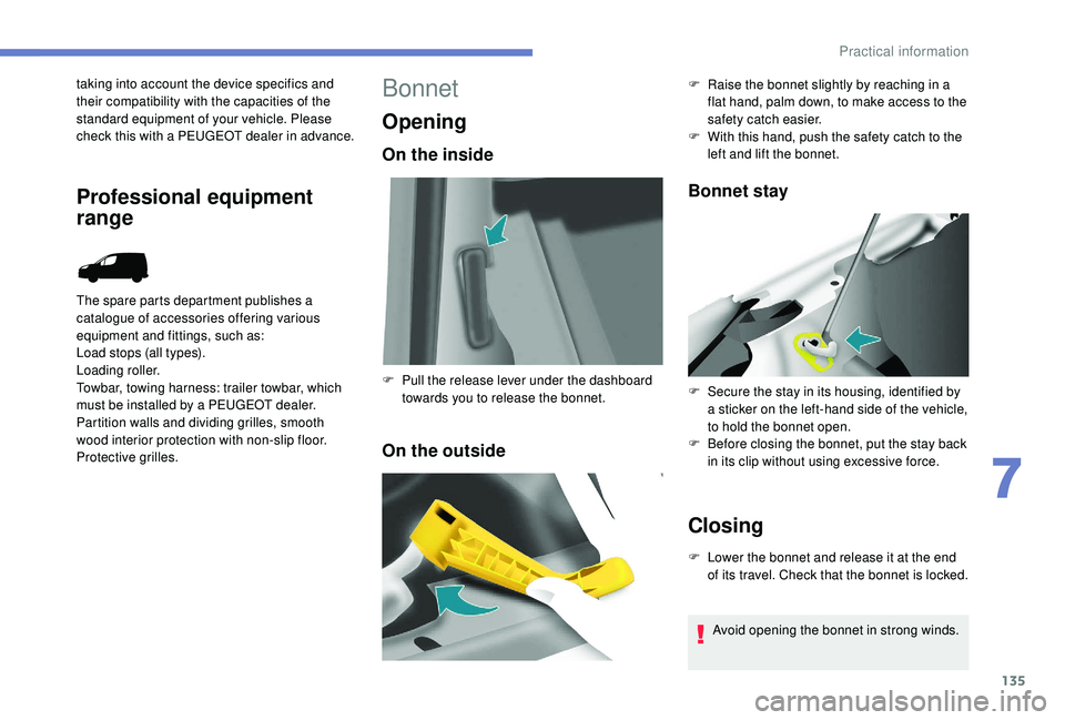
Opening
On the inside
On the outsideBonnet stay
Closing
F Lower the bonnet and release it at the end
of its travel. Check that the bonnet is locked.
F
P
ull the release lever under the dashboard
towards you to release the bonnet. F
R
aise the bonnet slightly by reaching in a
flat hand, palm down, to make access to the
safety catch easier.
F
W
ith this hand, push the safety catch to the
left and lift the bonnet.
F
S
ecure the stay in its housing, identified by
a sticker on the left-hand side of the vehicle,
to hold the bonnet open.
F
B
efore closing the bonnet, put the stay back
in its clip without using excessive force.
Avoid opening the bonnet in strong winds.
7
Practical information
Page 149 of 216

147
Never go underneath a vehicle that is
supported only by a jack (use an axle stand).
Never use an electric screwdriver instead of
the wheelbrace.
Refitting the repaired wheel
The wheel is refitted in the same way as the
spare wheel; do not forget to refit the wheel
trim.For more information on Identification
markings
, including the tyre label, refer to
the corresponding section.
For more information on Tyre under-
inflation detection , including
recommendations after changing a wheel
with a tyre under-inflation detection
sensor, refer to the corresponding section.
F
S
ecure the carrier on the hook, then raise
the carrier by tightening the bolt with the
wheelbrace.
F
T
ighten the bolt fully and check that the
wheel is held flat against the floor.
If not, repeat the procedure.
Fitting the wheel trim on
the rim
The valve of the wheel must be centred against
the notch on the wheel trim.
This position is essential to fit the wheel trim
properly on the metal rim. (In case of incorrect
positioning of the valve in line with the notch,
the anti-rotation system will be in contact with
the bolt heads and may be damaged if the user
persists in fitting the wheel trim in this incorrect
position.)
- Make sure that the wheel trim's outer edge is not pressed against the rim or lowered into it:
Correct wheel trim edge position.
8
In the event of a breakdown