2020 MERCEDES-BENZ GLS SUV weight
[x] Cancel search: weightPage 430 of 549
Ve
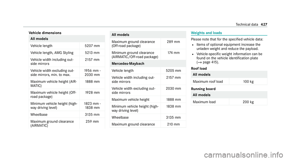
hicle dimensions All models
Ve
hicle lengt h5 207 mm
Ve hicle length, AMG Styling 52 13mm
Ve hicle width including out‐
side mir rors 21
57 mm
Ve hicle width excluding out‐
side mir rors, min. tomax. 19
56 mm -
2030 mm
Maximum vehicle height (AIR‐
MATIC) 18
88 mm
Maximum vehicle height (Off-
ro ad pac kage) 19
28 mm
Minimum vehicle height (high‐
wa y driving le vel) 18
23 mm -
18 38 mm
Wheelbase 3135 mm
Maximum ground clea rance
(AIRMATIC) 259 mm All models
Maximum ground clearance
(Off-road pa
ckage) 289 mm
Minimum ground clearance
(AIRMATIC/Off- road pac kage) 17
4 mm Mercedes‑Maybach
Ve
hicle lengt h5 205 mm
Ve hicle width including out‐
side mir rors 21
57 mm
Ve hicle width excluding out‐
side mir rors 2030 mm
Maximum vehicle height 1888 mm
Minimum vehicle height (high‐
wa y driving le vel) 18
38 mm
Wheelbase 3135 mm
Maximum ground clea rance 210 mm We
ights and loads Please no
tethat forth e specified vehicle data:
R Items of optional equipment increase the
unladen weight and reduce the pa yload.
R Vehicle-specific weight information can be
fo und on theve hicle identification plate
(/ page 415).
Ro of load All models
Maximum
roof load 100kg Ru
nning board All models
Maximum load
200kg Te
ch nical da ta427
Page 431 of 549
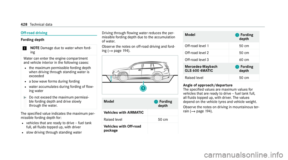
Off-road driving
Fo
rding dep th
* NO
TEDama gedue towate r when ford‐
ing Wa
ter can enter the engine compartment
and vehicle interior in thefo llowing cases:
R the maximum permissible ford ing dep th
when driving thro ugh standing water is
ex ceeded
R a bow wavefo rm s during ford ing
R wate r accumulates during ford ing of flow‐
ing water #
Do not exceed the maximum permissi‐
ble ford ing dep thand drive slowly
th ro ugh thewa ter. The specified
value indicates the maximum per‐
missible ford ing dep thfor:
R vehicles that are ready todrive – fuel tank
full, all fluids topped up, with driver
R slow driving thro ugh standing water Driving
thro ugh flow ing waterre duces the per‐
missible ford ing dep thdue tothe accumulation
of wate r.
Obser vethe no tes on off-road driving and ford‐
ing (/ page194). Mo
del
1
1Fording
dep th
Ve hicles with AIRMATIC
Ra ised le vel5 0 cm
Ve hicles with Off-road
pac kage Model
1
1Fording
dep th
Off-road le vel15 0 cm
Off-road le vel25 0 cm
Off-road le vel36 0 cm Mercedes-Maybach
GLS 600 4MATIC
1 1
Fording
dep th
Ra ised le vel5 0 cm Angle of approach/departure
The speci
fied values are maximum values for
ve hicles that are ready todrive – fuel tank full,
all fluids topped up, with driver. The values
depend on theve hicle tyres and vehicle weight.
Obser vethe no tes on driving in mountainous ter‐
ra in (/ page194). 428
Tech nical da ta
Page 434 of 549
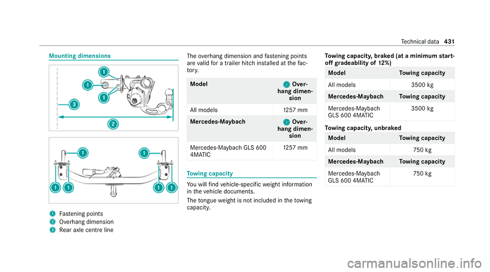
Mounting dimensions
1
Fastening points
2 Overhang dimension
3 Rear axle centre line The
overhang dimension and fastening points
are valid for a trailer hitch ins talled at thefa c‐
to ry. Model
2 2Over‐
hang dimen‐ sion
All model s1 257 mm Mercedes‑Maybach
2 2Over‐
hang dimen‐ sion
Mercedes-Mayba chGLS 600
4MATIC 12
57 mm To
wing capacity Yo
u will find vehicle-specific weight information
in theve hicle documents.
The tongue weight is not included in theto wing
capacity. To
wing capacit y,braked (at a minimum start-
off gradeability of 12%) Model
Towing capacity
All models 3500kg Mercedes‑Maybac
hTowing capacity
Mercedes-Maybach
GLS 600 4MATIC 3500
kg To
wing capacit y,unbraked Model
Towing capacity
All models 750kg Mercedes‑Maybac
hTowing capacity
Mercedes-Maybach
GLS 600 4MATIC 75
0kg Te
ch nical da ta431
Page 435 of 549
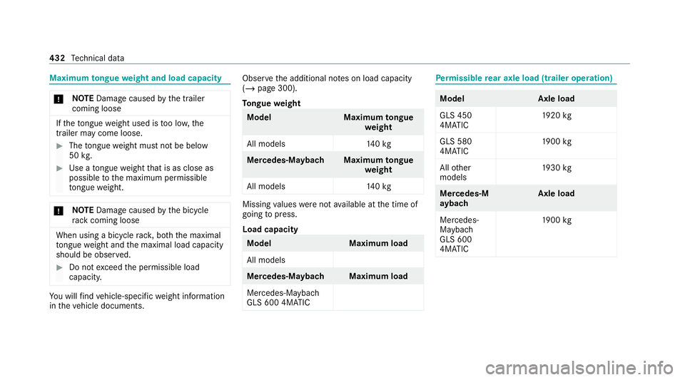
Maximum
tongue weight and load capacity *
NO
TEDama gecaused bythe trailer
coming loose If
th eto ngue weight used is too lo w,the
trailer may come loose. #
The tongue weight must not be below
50 kg. #
Use a tongue weight that is as close as
possible tothe maximum permissible
to ngue weight. *
NO
TEDama gecaused bythe bicycle
ra ck coming loose When using a bicycle
rack , bo th th e maximal
to ngue weight and the maximal load capacity
should be obser ved. #
Do not exceed the permissible load
capacity. Yo
u will find vehicle-specific weight information
in theve hicle documents. Obser
vethe additional no tes on load capacity
(/ page 300).
To ngue weight Model
Maximumtongue
we ight
All models 140kg Mercedes‑Maybac
hMaximum tongue
we ight
All models 140kg Missing
values werenot available at the time of
going topress.
Load capacity Model
Maximum load
All models Mercedes‑Maybac
hMaximum load
Mercedes-Mayba ch
GLS 600 4MATIC Pe
rm issible rear axle load (trailer operation) Model
Axle load
GLS 450
4MATIC 19
20 kg
GLS 580
4MATIC 19
00 kg
All other
models 19
30 kg Mercedes‑M
ay
bach Axle load
Mercedes-
Maybach
GLS 600
4MATIC 19
00 kg 432
Tech nical da ta
Page 438 of 549
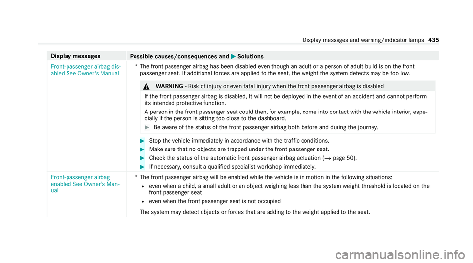
Display messages
Possible causes/consequences and M
MSolutions
Front-passenger airbag dis-
abled See Owner's Manual *T
he front passenger airbag has been disabled eventh ough an adult or a person of adult build is on the front
passenger seat. If additional forc es are applied tothe seat, thewe ight the sy stem de tects may be too lo w. &
WARNING ‑ Risk of inju ryor eve nfa ta l injury when the front passenger airbag is disabled
If th e front passenger airbag is disabled, It will not be deplo yed in theeve nt of an accident and cannot pe rform
its intended pr otective function.
A person in the front passenger seat could then, forex ample, come into con tact wi th theve hicle interior, espe‐
cially if the person is sitting too close tothe dashboard. #
Beaware of thest atus of the front passenger airbag bo thbefore and during the journe y. #
Stop theve hicle immediately in accordance with the traf fic conditions. #
Makesure that no objects are trapped under the front passenger seat. #
Check thest atus of the automatic front passenger airbag actuation (/ page 50). #
If necessar y,consult a qualified specialist workshop immediatel y.
Front-passenger airbag
enabled See Owner's Man-
ual *T
he front passenger airbag will be enabled while theve hicle is in motion in thefo llowing situations:
R even when a child, a small adult or an object weighing less than the sy stem weight thre shold is located on the
front passenger seat
R even when the front passenger seat is not occupied
The sy stem may de tect objects or forc es that are adding tothewe ight applied tothe seat. Display messages and
warning/indicator lamps 435
Page 529 of 549
Displ
aying weather information............ .329
Moving.................................................. 328
Selecting the map orientation............... 328
Setting the map scale............................ 328
Switching mo torw ay information on/
off......................................................... 328
Massage prog rammes
Overview................................................ 121
Re setting the settings............................1 22
Massage prog rams
Selecting the front seats........................ 121
Massage settings Resetting...............................................1 22
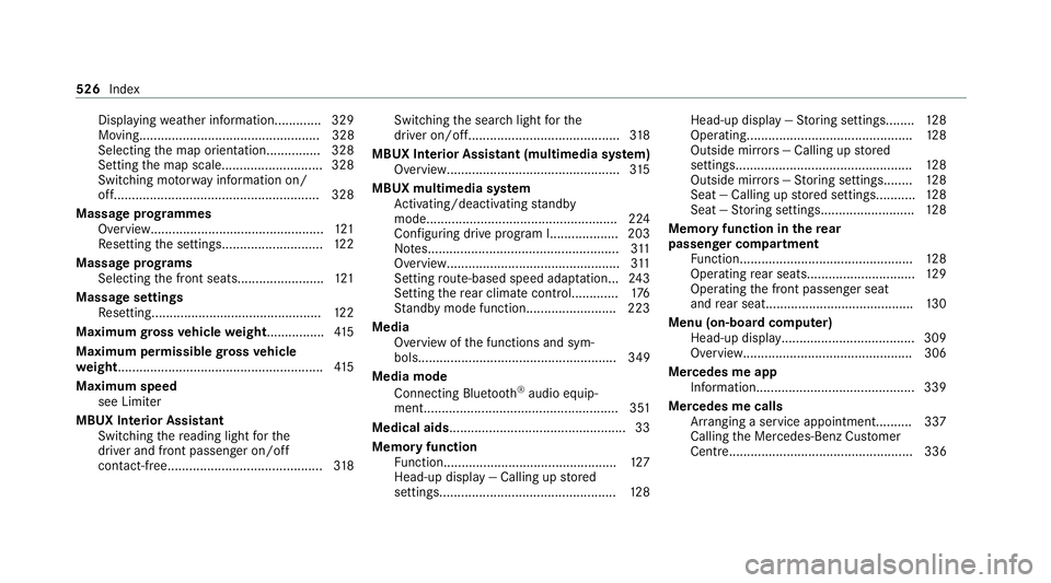
Maximum gross vehicle weight ................ 41 5
Maximum permissible gross vehicle
we ight ........................................................ .415
Maximum speed see Limiter
MBUX Interior Assistant Switching there ading light forthe
driver and front passenger on/off
con tact-free........................................... 318Switching
the sear chlight forthe
driver on/off.......................................... 318
MBUX Interior Assistant (multimedia sy stem)
Overview............................................... .315
MBUX multimedia sy stem
Ac tivating/deactivating standby
mode.................................................... .224
Con figuring drive program I...................203
No tes..................................................... 311
Overview................................................3 11
Setting route-based speed adap tation... 24 3
Setting there ar climate control............ .176
St andby mode function........................ .223
Media Overview of the functions and sym‐
bols....................................................... 349
Media mode Connecting Blue tooth®
audio equip‐
ment...................................................... 351
Medical aids ................................................ .33
Memory function Function................................................ 127
Head-up display — Calling up stored
settings................................................. 12 8Head-up display —
Storing settings........ 12 8
Operating..............................................1 28
Outside mir rors — Calling up stored
settings................................................. 12 8
Outside mir rors —St oring settings........1 28
Seat — Calling up stored settings........... 12 8
Seat — Storing settings.......................... 12 8
Memory function in there ar
passenger comp artment
Fu nction................................................ 12 8
Operating rear seat s.............................. 12 9
Operating the front passenger seat
and rear seat........................................ .130
Menu (on-board comp uter)
Head-up displa y..................................... 309
Overview............................................... 306
Mercedes me app Information............................................ 339
Mercedes me calls Arranging a service appointment.......... 337
Calling the Mercedes-Benz Cus tomer
Centr e................................................... 336 526
Index
Page 539 of 549
Fa
stening points (trailer hitch)............... 431
Information............................................ 413
Mounting dimensions (trailer hitch)....... 431
No tes (trailer hitch)............................... 430
Overhang dimension (trailer hitch)........4 31
Ra dio operating permits.........................4 15
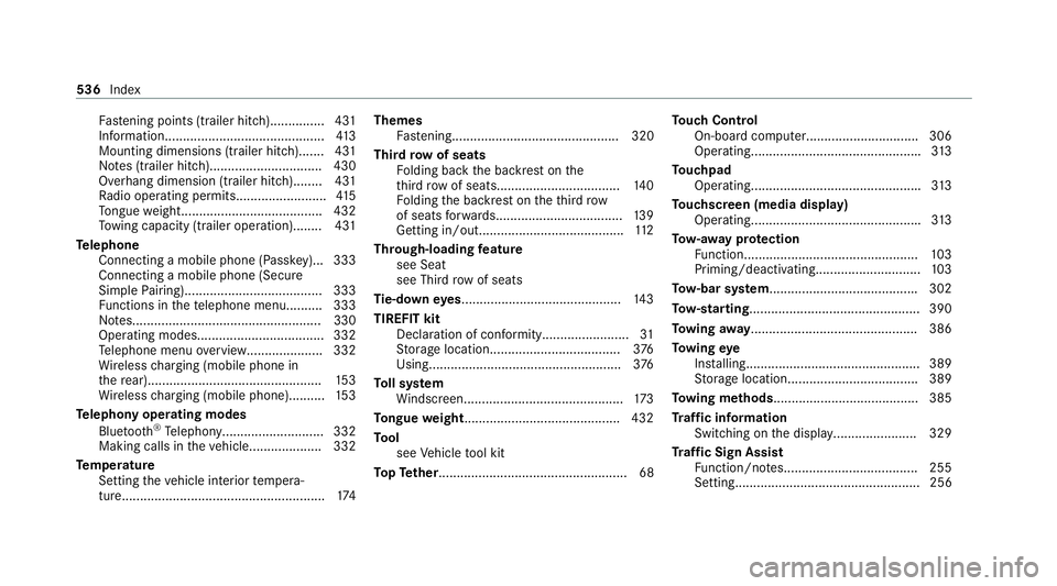
To ngue weight...................................... .432
To wing capacity (trailer operation )........ 431
Te lephone
Connecting a mobile phone (Passk ey)... 333
Connecting a mobile phone (Secure
Simple Pairing)...................................... 333
Fu nctions in thete lephone men u.......... 333
No tes....................................................3 30
Operating modes................................... 332
Te lephone menu overvie w..................... 332
Wi reless charging (mobile phone in
th ere ar)............................................... .153
Wi reless charging (mobile phone).......... 15 3
Te lephony operating modes
Blue tooth ®
Te lephony........................... .332
Making calls in theve hicle....................3 32
Te mp erature
Setting theve hicle interior temp era‐
ture........................................................ 174Themes
Fastening.............................................. 320
Third row of seats
Fo lding back the backrest on the
th ird row of seats.................................. 14 0
Fo lding the backrest on theth ird row
of seats forw ards................................... 13 9
Getting in/out........................................ 11 2
Through-loading feature
see Seat
see Third rowof seats
Ti e-d owney es ............................................ 14 3
TIREFIT kit Declaration of conformity........................ 31
St orage location.................................... 376
Using.....................................................3 76
To ll sy stem
Wi ndsc reen............................................ 173
To ngue weight .......................................... .432
To ol
see Vehicle tool kit
To pTe ther.................................................... 68 To
uch Control
On-board computer............................... 306
Operating.............................................. .313
To uchpad
Operating.............................................. .313
To uchscreen (media display)
Operating.............................................. .313
To w- aw ay protection
Fu nction................................................ 103
Priming/deactivating.............................1 03
To w- bar sy stem........................................ .302
To w- starting............................................... 390
To wing away.............................................. 386
To wing eye
Ins talling............................................... .389
St orage location.................................... 389
To wing me thods ........................................ 385
Tr af fic information
Swit ching on the display....................... 329
Tr af fic Sign Assist
Fu nction/no tes..................................... 255
Setting................................................... 256 536
Index
Page 540 of 549
Sy
stem limitations................................. 255
Tr ailer hitch
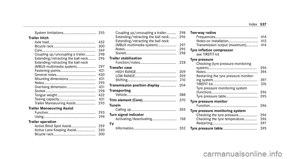
Axle load.............................................. .432
Bicycle rack ........................................... 300
Ca re...................................................... 369
Coupling up/uncoupling a traile r.......... 298
Extending/r etra cting the ball nec k........ 296
Extending/r etra cting the ball neck
(MBUX multimedia sy stem)...................2 97
Fa stening points.................................... 431
General no tes........................................4 30
Mounting dimensions............................ 431
No tes....................................................2 95
Overhang dimension.............................. 431
Soc ket.................................................. .298
To ngue weight...................................... .432
To wing capacity.................................... .431
Tr ailer Manoeuv ring Assi st.................... 293
Tr ailer Manoeuvring Assist
Fu nction................................................ 293
Using..................................................... 294
Tr ailer operation
Ac tive Blind Spot Assi st......................... 259
Ac tive Lane Keeping Assist...................2 60
Bicycle rack ........................................... 300 Coupling up/uncoupling a traile
r.......... 298
Extending/r etra cting the ball nec k........ 296
Extending/r etra cting the ball neck
(MBUX multimedia sy stem)...................2 97
No tes....................................................2 95
Soc ket.................................................. .298
Tr ailer stabilisation
Fu nction/no tes..................................... 228
Tr ansfer case
HIGH RANGE......................................... 209
LO W RANGE.......................................... 209
Shifting..................................................2 10
Tr ansmission position display................. 204
Tr anspo rting
Ve hicle..................................................3 88
Tr im element (Care)................................. .370
Tu neIn
Calling up..............................................3 55
Tu rn signal indicator
Ac tivating/deactivating......................... 15 8
TV Information............................................ 352 Tw
o-w ayradios
Fr equencies........................................... 414
No tes on ins tallation.............................. 413
Tr ansmission output (maximum )............ 414
Ty re inflation compressor
see TIREFIT kit
Ty re pressure
Checking (ty repressure monitoring
sy stem)................................................. 396
No tes..................................................... 394
Re starting the tyre pressure monitor‐
ing sy stem.............................................3 97
TIREFIT kit..............................................3 76
Ty re pressure monitoring sy stem
(function)............................................... 396
Ty re pressure table................................ 395
Ty re pressure moni tor
Fu nction................................................ 396
Ty re pressure moni toring sy stem
Checking the tyre pressure...................3 96
Che cking the tyre temp erature............. 396
Re starting.............................................. 397
Ty re pressure table ................................... 395 Index
537