2020 MERCEDES-BENZ GLS SUV radio
[x] Cancel search: radioPage 358 of 549
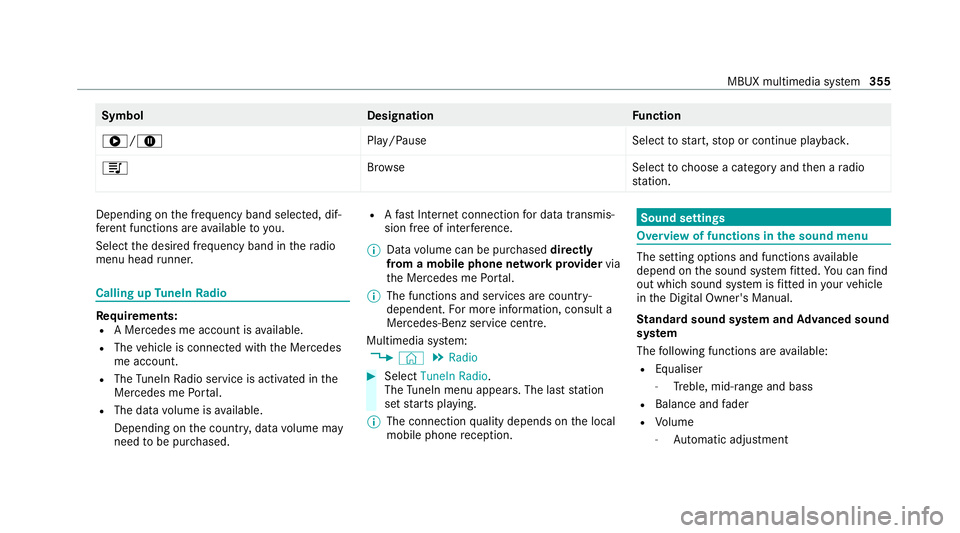
Symbol
DesignationFunction
6/8 Play/PauseSelecttostart, stop or continue playbac k.
5 Brows eS electtochoose a category and then a radio
st ation. Depending on
the frequency band selected, dif‐
fe re nt functions are available to you.
Select the desired frequency band in thera dio
menu head runner. Calling up
TuneIn Radio Re
quirements:
R A Mercedes me account is available.
R The vehicle is connected with the Mercedes
me account.
R The TuneIn Radio service is activated in the
Mercedes me Portal.
R The data volume is available.
Depending on the count ry, data volume may
need tobe pur chased. R
Afast Internet connection for data transmis‐
sion free of inter fere nce.
% Data volume can be pur chased directly
from a mobile phone network pr ovider via
th e Mercedes me Portal.
% The functions and services are countr y-
dependent. For more information, consult a
Mercedes-Benz service centre.
Multimedia sy stem:
4 © 5
Radio #
Select TuneIn Radio.
The TuneIn menu appears. The la st station
set starts playing.
% The connection quality depends on the local
mobile phone reception. Sound settings
Overview of functions in the sound menu
The setting options and functions
available
depend on the sound sy stem fitted. You can find
out which sound sy stem is fitted in your vehicle
in the Digital Owner's Manual.
St andard sound sy stem and Advanced sound
sy stem
The following functions are available:
R Equaliser
- Treble, mid-range and bass
R Balance and fader
R Volume
- Automatic adju stment MBUX multimedia sy
stem 355
Page 416 of 549
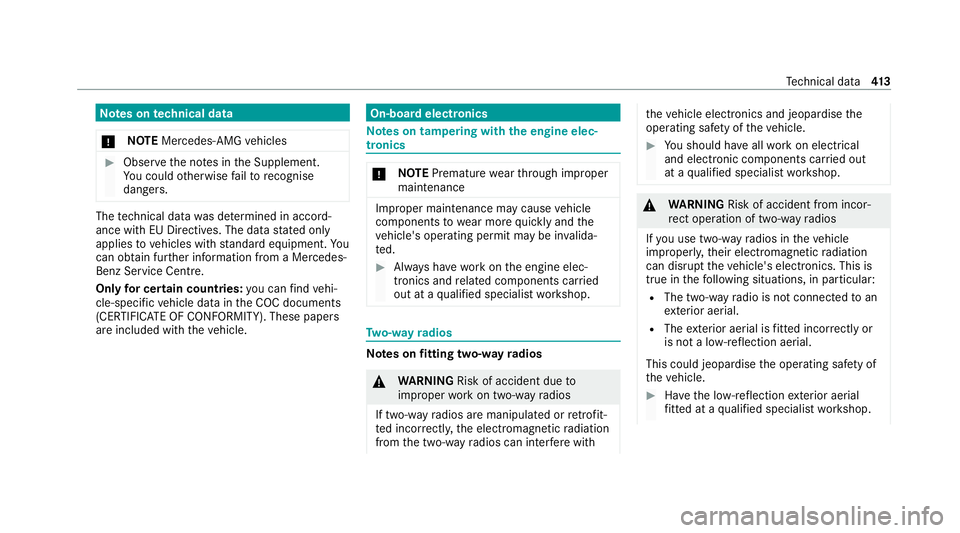
Note
s ontech nical data
* NO
TEMercedes-AMG vehicles #
Obser vethe no tes in the Supplement.
Yo u could otherwise failto recognise
dangers. The
tech nical da tawa s de term ined in accord‐
ance with EU Directives. The data stated on ly
applies tovehicles with standard equipment. Yo u
can obtain fur ther information from a Mercedes-
Benz Service Centre.
Only for ce rtain countries: you can find vehi‐
cle-specific vehicle data in the COC documents
(CERTIFIC ATE OF CONFORMITY). These pape rs
are included with theve hicle. On-board electronics
Note
s on tampering with the engine elec‐
tronics *
NO
TEPremature wearthro ugh improper
main tenance Improper maintenance may cause
vehicle
components towe ar more quickly and the
ve hicle's operating permit may be in valida‐
te d. #
Alw ays ha vewo rkon the engine elec‐
tronics and related components car ried
out at a qualified specialist workshop. Tw
o-w ayradios Note
s onfitting two-w ayradios &
WARNING Risk of accident due to
improper workon two-w ayradios
If two-w ayradios are manipulated or retrofit‐
te d incor rectl y,the electromagnetic radiation
from the two-w ayradios can inter fere with th
eve hicle electronics and jeopardise the
operating saf ety of theve hicle. #
You should ha veall workon electrical
and electronic components car ried out
at a qualified specialist workshop. &
WARNING Risk of accident from incor‐
re ct ope ration of two-w ayradios
If yo u use two- wayra dios in theve hicle
improperly, their electromagnetic radiation
can disrupt theve hicle's electronics. This is
true in thefo llowing situations, in particular:
R The two-w ayradio is not connec tedto an
ex terior aerial.
R The exterior aerial is fitted inco rrectly or
is not a lo w-reflection aerial.
This could jeopardise the operating saf ety of
th eve hicle. #
Have the lo w-reflection exterior aerial
fi tted at a qualified specialist workshop. Te
ch nical da ta413
Page 417 of 549
#
When operating two-w ayradios in the
ve hicle, alw ays connect them tothe
lo w- reflection exterior aerial. *
NO
TEInva lidation of the operating per‐
mit due tofailure tocomply wi th the
instructions for ins tallation and use The operating permit may be in
validated if
th e instructions for ins tallation and use of
two-w ayradios are not obser ved. #
Only use appr oved frequency bands. #
Obser vethe maximum permissible out‐
put po wer in these frequency bands. #
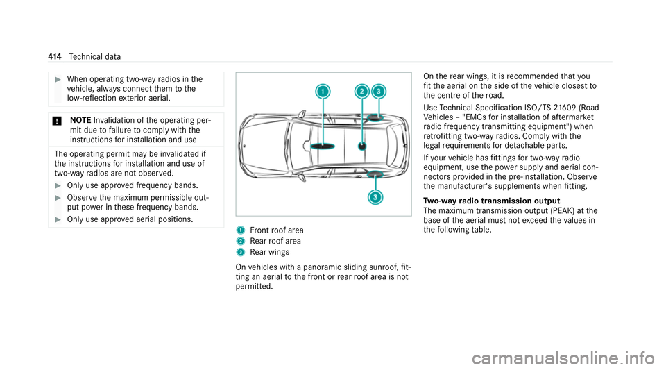
Only use appr oved aerial positions. 1
Front roof area
2 Rear roof area
3 Rear wings
On vehicles with a panoramic sliding sunroof, fit‐
ting an ae rial to the front or rear roof area is not
permitted. On
there ar wings, it is recommended that you
fi t th e aerial on the side of theve hicle closest to
th e cent reofthero ad.
Use Tech nical Specification ISO/TS 21609 (Road
Ve hicles – "EMCs for ins tallation of af term arket
ra dio frequency transmitting equipment") when
re trofitting two-w ayradios. Comply with the
legal requirements for de tach able parts.
If yo ur vehicle has fittings for two-w ayradio
equipment, use the po wer supp lyand aerial con‐
nec tors prov ided in the pre-ins tallation. Obser ve
th e manufacturer's supplements when fitting.
Tw o-w ayradio transmission output
The maximum transmission output (PEAK) at the
base of the aerial must not exceed theva lues in
th efo llowing table. 414
Tech nical da ta
Page 418 of 549
Fr
equency band and maximum transmission
output Fr
equency band Maximum transmis‐
sion output
Sho rtwa ve
3 - 54 MHz 10
0 W
4 m frequency band
74 - 88 MHz 30 W
2 m frequency band
14 4 - 174 MHz 50 W
Te rrestrial Trunked
Ra dio (TETRA)
380 - 460 MHz 10 W
70 cm frequency
band
420 - 450 MHz 35 W
Tw o-w ayradio
(2G/3G/4G) 10 W The
following can be used in theve hicle without
re strictions:
R two-w ayradios with a maximum transmission
output of up to100 mW
R RF transmitters with transmitter frequencies
in the 380 - 410 MHz frequency band and a
maximum transmission output of up to2 W
(TETRA)
R mobile phones (2G/3G/4G)
There are no restrictions when positioning the
aerial on the outside of theve hicle forth efo llow‐
ing frequency bands:
R Terrestrial Trunked Radio (TETRA)
R 70 cm frequency band
R 2G/3G/4G Ra
dio ope rating permits forve hicle comp o‐
nents
Manufacturer information about wireless vehicle
components can be found using theke y phrase
"Radio operating permits" in the Digital Owner's Manual in
theve hicle, on the internet and in the
app. Ve
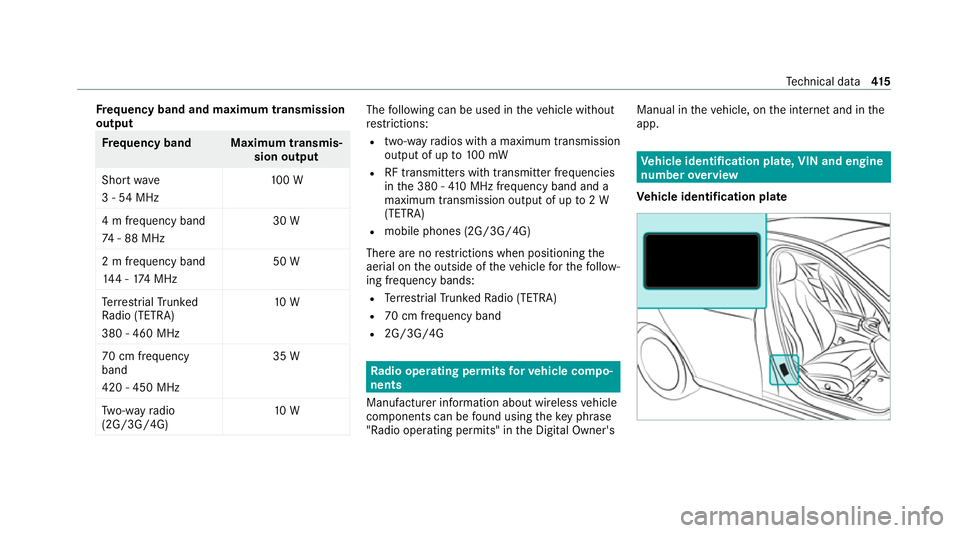
hicle identification plate, VIN and engine
number overview
Ve hicle identification plate Te
ch nical da ta415
Page 441 of 549
Display messages
Possible causes/consequences and M
MSolutions
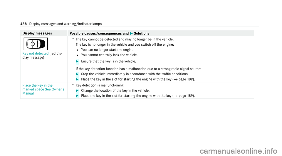
Á Key not detected (red dis‐
play message) *T
hekey cannot be de tected and may no longer be in theve hicle.
The key is no lon ger in theve hicle and you swit choff the engine:
R You can no lon gerst art the engine.
R You cannot centrally lock theve hicle. #
Ensure that theke y is in theve hicle.
If th eke y de tection function has a malfunction due toast ro ng radio signal source: #
Stop theve hicle immediately in accordance with the traf fic conditions. #
Place theke y in the slot forst arting the engine with theke y (/ page189).
Place the key in the
marked space See Owner's
Manual *K
eydetection is malfunctioning. #
Change the location of theke y in theve hicle. #
Place theke y in the slot forst arting the engine with theke y (/ page189). 438
Displaymessa ges and warning/indicator lamps
Page 485 of 549
Ty
re pressure moni torDisplay messages
Possible causes/consequences and M
MSolutions
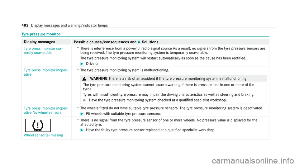
Tyre press. monitor cur-
rently unavailable *T
here is inter fere nce from a po werful radio signal source As a result, no signals from the tyre pressure sensors are
being recei ved. The tyre pressure monitoring sy stem is temp orarily una vailable.
The tyre pressure monitoring sy stem will restart automatically as soon as the cause has been rectified. #
Drive on.
Tyre press. monitor inoper-
ative *T
he tyre pressure monitoring sy stem is malfunctioning. &
WARNING Thereis a risk of an accident if the tyre pressure monitoring sy stem is malfunctioning
The tyre pressure monitoring sy stem cann otissue a warning if there is pressure loss in one or more of the
tyres.
Ty res with insuf ficient tyre pressure may impair the driving characteristics as well as steering and braking. #
Have the tyre pressure monitoring sy stem checked at a qualified specialist workshop. Tyre press. monitor inoper-
ative No wheel sensors
*T
he wheels fitted do not ha vesuitable tyre pressure sensors. The tyre pressure monitoring sy stem is deactivated. #
Fit wheels with suitable tyre pressure sensors.
h
Wheel sensor(s) missing *T
here is no signal from the tyre pressure sensor of one or more wheels. Nopressure value is displa yedfo rthe
af fected tyre. #
Have thefa ulty tyre pressure sensor replaced at a qualified specialist workshop. 482
Display messages and warning/indicator lamps
Page 524 of 549

Exterior lighting
see Lights
Exterior lighting (care) .............................. 369F
Fa tigue de tection
see ATTENTION ASSIST
Fire extinguisher........................................ 374
Fi rs t-aid kit (soft sided) ............................373
Flacon Inserting/removin g............................... 178
Flat towing
see Tow- bar sy stem
Flat tyre MOEx tended tyres................................. 375
No tes..................................................... 374
TIREFIT kit..............................................3 76
Wheel chang e....................................... .402
Floor mats.................................................. 154
Fo g light (extended range) ....................... 16 0
Fo il co vering
Ra dar and ultrasonic sensor s................ 224Fo
lding table .............................................. 13 5
Fr ag rance
see Fragrance sy stem
Fr ag rance sy stem
Inserting/removing theflacon.............. .178
Setting................................................... 178
Fr ee driving mode
St arting................................................. .276
Fr ee software.............................................. 38
Fr equencies
Mobile phon e......................................... 414
Tw o-w ayradio........................................ 414
Fr ont airbag (driver, front passenger)...... .45
Fr ont passenger seat
Ad justing from the driver's seat............ 108
Ad justing from there ar........................ .109
Fr ont passenger seat
see Seat
Fu el
Ad ditives...............................................4 20
Diesel.................................................... 420
E10....................................................... .419
Fu elreser ve........................................... 421 Low outside
temp eratures..................... 420
Pe trol..................................................... 419
Quality (diesel )...................................... 420
Quality (p etro l)...................................... .419
Re fuelling............................................... 211
Sulphur content..................................... 419
Ta nk content.......................................... 421
Fu nction seat
see Door cont rol panel
Fu nction seat (rear)
see Seat (rear)
Fu ses
Before replacing a fuse.......................... 390
Fu se assignment diagram..................... 390
Fu se box in the engine compartmen t.... 391
Fu se box in the front passenger foot‐
we ll....................................................... 392
Fu se box in the load compartment........ 392
Fu se box on the dashboard................... 392
No tes....................................................3 90 G
Garage door opener Clearing the memory.............................2 21 Index
521
Page 526 of 549
Identification pla
te
Engine.................................................... 41 5
ve hicle................................................... 41 5
Ignition Swit ching on (S tart/S top button).......... 187
Ignition key
see Key
Immobiliser ................................................ 102
Implied warranty
Ve hicle.................................................... 34
In-Car Of fice
Fe atures................................................ 339
Indicator lamps see Warning/indicator lamps
Individual drive prog ram
Con figuring........................................... 203
Selecting............................................... 203
Inspection see ASS YST PLUS
Instrument clus ter
Fu nction/no tes............................. 304, 305
In stru ment display
Fu nction/no tes..................................... 305 Instrument clu
ster................................... 10
Wa rning/indicator lamps...................... 490
Instrument display and on-boa rd
compu ter
Fu nction/no tes..................................... 304
In te lligent Light Sy stem
Ac tive headla mps.................................. 15 9
Ad aptive Highbeam Assist Plus.............. 161
Corne ring light....................................... 15 9
Fo g light (extended range)..................... 16 0
Mo torw ay mode..................................... 16 0
Overview............................................... 15 9
Switching on/of f.................................... 161
Interior lighting Adjusting............................................... 16 3
Ambient lighting.................................... 16 4
Re ading lam p......................................... 16 3
Switch-off del aytime............................. 16 4
Interior pr otection
Fu nction................................................ 103
Priming/deactivating.............................1 04
Internet radio
see TuneIn Ionisation
Activating/deactivating (MBUX mul‐
timedia sy stem).....................................1 78
iPhone ®
see Smartphone integ ration
ISOFIX child seat securing sy stem
Fitting..................................................... .64
Seats suitable for attaching..................... 62 J
Jack Declaration of conformity........................ 30
Storage location.................................... 401
Jump-start connection General no tes........................................ 382 K
Key Acoustic locking verification signal......... 79
Battery.................................................... 80
Emer gency key........................................ 79
Energy consum ption................................ 79
Fe atures................................................. .78
Ke yring attachment................................ 79 Index
523