2020 MERCEDES-BENZ CLS COUPE tow
[x] Cancel search: towPage 199 of 469
Also,
the speed is reduced if the turn signal indi‐
cator tochange lanes is swit ched on and one of
th efo llowing situations is de tected:
R Turning off at junctions
R Driving on slowing-down lanes
R Driving on lanes adjacent toslowing-down
lanes
The driver is responsible forch oosing theright
speed and observing other road users. This
applies in particular tojunctions, roundabouts
and traf fic lights, as route-based speed adap ta‐
tion does not brake theve hicle toast andstill.
When route guidance is active, thefirs t speed
adjustment is car ried out automaticall y.Ifthe
turn signal indica tor is switched on, the selected
ro ute is confirmed and fur ther speed adjustment
is activated.
Speed adap tation is cancelled in thefo llowing
cases:
R Ifth e turn signal indicator is switched off
before thero ute event.
R Ifth e driver depresses the accelerator or
brake pedal during the process. Sy
stem limits
Ro ute-based speed adap tation does not take
ri ght of wayre gulations into account. The driver
is responsible for complying with road traf fic
re gulations and driving at a suitable speed.
The speed adap tation made bythe sy stem may
not alw ays be suitable, particular lyin thefo llow‐
ing situations:
R thero ad's course not clear lyvisible
R road nar rowing
R varying maximum permissible speeds in indi‐
vidual lanes
R wetro ad sur faces, snow or ice
R when towing a trailer
In these situations the driver must inter vene
acco rding ly. &
WARNING Risk of accident in spi teof
ro ute-based speed adap tation
Ro ute-based speed adap tation can malfunc‐
tion or be temp orarily una vailable in thefo l‐
lowing situations: R
Ifth e driver does not follow the calcula‐
te dro ute
R If map data is not up-to-date or available
R Intheeve nt of roadwor ks
R In bad weather or road conditions
R Ifth e accelera tor pedal is depressed
R Intheeve nt of electronical lydispla yed
speed limitations #
Adapt the speed tothe traf fic situation. Setting
route-based speed adaptation
Re quirements:
R Active Dis tance Assi stDISTRONIC is acti va‐
te d.
R ECO Assist is active. 19 6
Driving and pa rking
Page 202 of 469
R
There is glare, e.g. from oncoming traf fic,
di re ct sunlight or reflections.
R Insuf ficient road illumination.
R The windsc reen is dirty, mis ted up, damaged
or co vered in the vicinity of the camera, e.g.
by ast icke r.
R No, or se veral, unclear lane markings are
present for one lane, or the markings change
qu ickl y,forex ample, in a con stru ction area
or junctions.
R The lane markings are wornaw ay, dark or
co vered up, e.g. bydirt or sno w.
R Ifth e dis tance totheve hicle in front is too
short and thus the lane markings cann otbe
de tected.
R The road is nar rowand winding.
R There are obs tacles on the lane or projecting
out into the lane, such as object mar kers.
The sy stem does not pr ovide assis tance in the
fo llowing conditions:
R On tight bends and when turning.
R When crossing junctions. R
Atroundabouts or tollst ations.
R When towing a trailer.
R When the tyre pressure is too lo w. &
WARNING Risk of accident if Active
St eering Assist unexpectedly stops func‐
tioning
If th e sy stem limits of Active Steering Assist
are reached there is no guarantee that the
sy stem will remain active or will keep the
ve hicle in lane. #
Alw ayske ep your hands on thesteering
wheel and obser vethe tra ffic carefull y. #
Alw aysst eer theve hicle paying atten‐
tion totraf fic conditions. &
WARNING Risk of accident if Active
St eering Assist unexpectedly inter venes
The de tection of lane markings and objects
may malfunction and cause unexpected
st eering inter ventions. #
Steer according totraf fic conditions. Ac
tivating/deactivating Active Steering
Assist
Re quirements:
R ESP ®
is activated, but is not inter vening.
R Active Dis tance Assi stDISTRONIC is acti va‐
te d.
Multimedia sy stem:
4 © 5
Settings 5
Quick access #
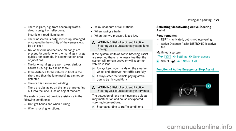
Select aAct. Steer. Asst . Fu
nction of Active Eme rgency Stop Assist Driving and parking
19 9
Page 234 of 469
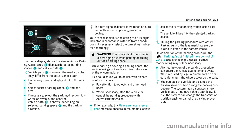
The media display sho
ws the view of Active Park‐
ing Assist. Area 2displa ysdetected pa rking
spaces 4and vehicle path 3.
% Vehicle path 3shown on the media display
may dif fer from the actual vehicle path. #
If a parking space is displa yed: stop theve hi‐
cle. #
Select desired parking space 4and con‐
fi rm. #
If necessar y,select the parking direction: for‐
wa rds or reve rse, and confi rm.
Ve hicle path 3is shown, depending on
selected parking space 4and the parking
direction. %
The turn signal indicator is switched on auto‐
matically when the parking procedure
begins.
Yo u are responsible for selecting the turn signal
indicator in accordance with the traf fic condi‐
tions. If necessar y,select the turn signal indica‐
to r according ly. &
WARNING Risk of accident due tovehi‐
cle swinging out while parking or pulling
out of a parking space
While parking or exiting a parking space, the
ve hicle swings out and can drive onto areas
of the oncoming lane.
This could cause youto collide wi thobjects
or other road users. #
Pay attention toobjects and other road
users. #
Where necessar y,stop theve hicle or
cancel the parking procedure with
Ac tive Parking Assist. #
If,forex ample, thePlease engage reverse
gear message appears in the media display: select
the cor responding transmission posi‐
tion.
The vehicle drives into the selected parking
space.
% During the parking procedure with Active
Pa rking Assist, the lane markings are dis‐
pla yed in green in the camera image.
On completion of the parking procedure, the
Ø Parking Assist finished, take control of
vehicle display message appears. Further
manoeuvring may still be necessar y. #
After completion of the parking procedure,
safeguard theve hicle against rolling away.
When requ ired bylegal requirements or local
conditions: turn the wheels towa rdsth eke rb.
% You can stop theve hicle and change the
transmission position du ring the parking pro‐
cedure. The sy stem then calculates a new
ve hicle path. If no new vehicle path is availa‐
ble, the sy stem can change the transmission
position again or cancel the parking proce‐
dure. Driving and parking
231
Page 237 of 469
R
Ifyo u shift the transmission position tok or
h when theve hicle is stationar y.
R Ifth e de tected obs tacle is less than appr ox.
1. 0 m away.
R Ifth e manoeuvring assis tant function is acti‐
va ted in the multimedia sy stem.
Sy stem limits
The per form ance of Drive AwayAssi stis limited
on inclines.
When driving with a trailer, Drive AwayAssi stis
not available.
% Also obse rveth e sy stem limits of Parking
Assist PARKTRONIC (/ page 224).
Fu nction of Cross Traf fic Alert
% Cross Traf fic Alert is only available forve hi‐
cles with Blind Spot Assist or Active Blind
Spot Assi st.
Cross Traf fic Alert can warndrivers of any cross‐
ing tra ffic when reve rsing and manoeuvring out
of a parking space. The radar sensors in the
bumper also monitor the area adjacent tothe
ve hicle. If a critical situation is de tected, the L
symbol appears inthe media display and
th eve hicle can be braked automatically.
If th era dar sensors are obstructed byvehicles
or other objects, de tection is not possible.
Cross Traf fic Alert is acti veunder thefo llowing
conditions:
R ifth eve hicle is reve rsing at a walking pace.
R manoeuvring assis tance is acti vated
( / page 234).
% Also obser vethe instructions on Blind Spot
Assist and Active Blind Spot Assi st
( / page 209).
Sy stem limits
Cross Traf fic Alert is not available on inclines.
Cross Traf fic Alert is not available when driving
with a trailer.
Ac tivating/deactivating manoeuv ring assis‐
tant
Multimedia sy stem:
4 © 5
Settings 5
Assistance
5 Camera & parking #
Activate/deactivate Manoeuvring assistance. %
Manoeuv ring assi stant must be active forthe
function of Drive AwayAssi st (/ page 233)
and Cross Traf fic Alert (/ page 234). Tr
ailer hitch Note
s on trailer operation *
NO
TEMercedes-AMG vehicles #
Obser vethe no tes in the Supplement.
Yo u could otherwise failto recognise
dangers. Obser
vethefo llowing no tes on theto ngue
we ight:
R Do not use a tongue weight that exceeds or
fa lls below the permissible tongue weight
R Use a tongue weight as close as possible to
th e maximum tongue weight
Do not exceed thefo llowing values:
R Perm issible towing capacity
R Perm issible rear axle load of theto wing vehi‐
cle 234
Driving and parking
Page 244 of 469

R
Alw ays distribute the load on the bicycle rack
as eve nly as possible across theve hicle's
longitudinal axis.
Mercedes-Benz recommends removing all
de tach able parts from bicycles (e.g. bask ets,
ch ild seats, rech arge able bat teries) before load‐
ing them onto the bicycle rack . This will impr ove
th e aerodynamic resis tance and centre of gr avity
of the bicycle rack.
Alw ays secure the bicycles topreve ntthem from
moving around and check them at regular inter‐
va ls to ensure that they are secure.
Do not use tarp aulins or other co vers. The driv‐
ing characteristics and rear view may be
impaired. In addition, aerodynamic resis tance
and the load on the trailer hitch will increase. Load distribution on
the bicycle rack
1 Vertical dis tance between centre of gr avity
and ball head
2 Horizon tal dis tance between centre of gr av‐
ity and ball head
3 The centre of gr avity is on theve hicle's
centre axis
Obse rveth efo llowing information when loading
th e bicycle rack: Loading
the bicycle rack 3 bicycles 4 bicycles
To talwe ight of
bicycle rack
and load Up
to75 kg Up to
10 0kg
Max. dis tance
1 420 mm 420 mm
Max. di stance
2 300 mm 400 mm When transpo
rting four bic ycles or with a total
we ight between 75kgand 100kg , alw ays use
bicycle rack s with additional support on the
trailer hitch guide pin. Ve
hicle towing instructions
The vehicle is not suitable forth e use of tow bar
sy stems that are used forflat towing or ding hy
to wing, forex ample. Attach ing and using tow bar
sy stems can lead todamage on theve hicle.
When you are towing a vehicle with tow bar sys‐
te ms, safe driving characteristics cannot be Driving and parking
241
Page 245 of 469
guaranteed
forth eto wing vehicle or theto wed
ve hicle. The vehicle-trailer combination may
swer vefrom side toside. Comply with the per‐
mitted towing me thods (/ page319) and the
instructions forto wing with bo thaxles on the
ground ( /page 320). 242
Driving and pa rking
Page 258 of 469
R
Clothing being worn(hat, shawl, scarf) may
be limiting the de tection area of the camera. Ke
ep the camera's field of vision clear.
R The camera is not operational. Consult a Mercedes-Benz service cent
re.
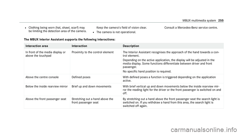
The MBUX In terior Assistant supports thefo llowing interactions: Interaction area
Interaction Description
In front of the media display or
abo vetheto uchpad Pr
ox imity tothe control element The Interior Assis tant recognises the approach of the hand towa rds a con‐
trol element.
Depending on the active application, the display will be adjus ted in the
media displa y.Some functions di fferentiate between driver and front
passenger.
No specific hand position is requ ired.
Abo vethe cent reconsole Defined poses With defined poses a function is triggered depending on the application
active.
Below the inside rearview mir rorB rief up and down mo vements With brief vertical up and down mo vements below the inside rearview mir‐
ro rth ere ading light forth e driver or the front passenger is switched on and
off.
Abo vethe front passenger seat Stretching out a hand ab ovethe
front passenger seat By
stre tching out a hand ab ovethe front passenger seat the sear chlight is
switched on. If you withdraw a hand from this area, the sear chlight is
switched off again. MBUX multimedia sy
stem 255
Page 268 of 469
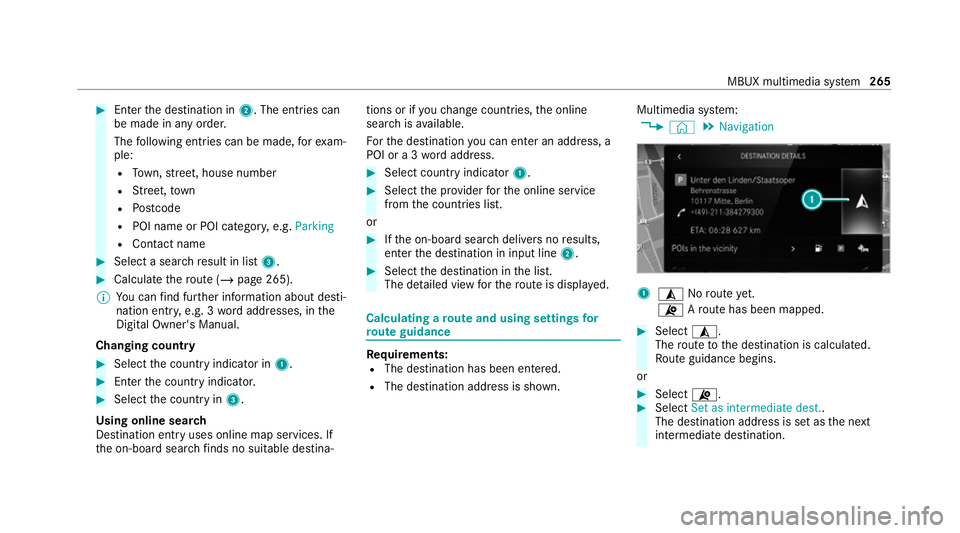
#
Enter the destination in 2. The entries can
be made in any order.
The following ent ries can be made, forex am‐
ple:
R Town, stre et, house number
R Street,to wn
R Postcode
R POI name or POI catego ry, e.g. Parking
R Contact name #
Select a sear chresult in list 3. #
Calculate thero ute (/ page 265).
% You can find fur ther information about desti‐
nation entry , e.g. 3wordaddresses, in the
Digital Owner's Manual.
Changing country #
Select the count ryindicator in 1. #
Enterth e count ryindicator. #
Select the count ryin3.
Using online sear ch
Destination entry uses online map services. If
th e on-board sear chfinds no suitable de stina‐ tions or if
youch ange countries, the online
sear chisavailable.
Fo rth e destination you can en ter an addre ss, a
POI or a 3 wordaddress. #
Select country indicator 1. #
Select the pr ovider forth e online service
from the count ries list.
or #
Ifth e on-board sear chdelivers no results,
enter the destination in input line 2. #
Select the destination in the list.
The de tailed view forth ero ute is displ ayed. Calculating a
route and using settings for
ro ute guidance Re
quirements:
R The destination has been entered.
R The destination address is shown. Multimedia sy
stem:
4 © 5
Navigation 1
¥ Noroute yet.
¦ Aro ute has been mapped. #
Select ¥.
The route tothe destination is calculated.
Ro ute guidance begins.
or #
Select ¦. #
Select Set as intermediate dest..
The destination address is set as the next
intermediate destination. MBUX multimedia sy
stem 265