2020 MERCEDES-BENZ CLS COUPE radio
[x] Cancel search: radioPage 5 of 469

Symbols
........................................................ 5At
agl ance .................................................... 6
Cockpit ........................................................... 6
Indica tor and warning lamps ........................ .10
Overhead contro l panel ................................ 12
Door control panel and seat adjustment ....... 14
Emergencies and breakdowns ...................... 16Digital Owner's Manual
.............................18
Calling up the Digital Owner's Manual ..........18 Genera
l notes............................................. 20
Pr otection of the environment ......................20
Ta ke -ba ckof end-of-life vehicles ...................20
Mercedes-Benz GenuineParts ....................... 21
Owner's Manual ...........................................22
Operating saf ety .......................................... .22
Declaration of conformity ............................. 24
Diagno stics connection ................................ 28
Qualified specialist workshop ....................... 29
Ve hicle registration ....................................... 30
Cor rect use of theve hicle ............................30 Information on
the REA CHregulation ........... 30
No tesfo r persons with electronic medi‐
cal aids ......................................................... 30
Implied warranty .......................................... .31
QR code forre scue card ...............................31
Data storage .................................................31
Copyright ...................................................... 35 Occupant saf
ety......................................... 36
Re stra int sy stem ...........................................36
Seat belts ..................................................... 38
Airbags ......................................................... 42
PRE-SAFE ®
sy stem ....................................... 49
Safely transporting children in theve hi‐
cle ................................................................. 51
No tes on pets in theve hicle .........................70 Opening and closing
.................................. 71
Ke y ................................................................ 71
Doo rs............................................................ 74
Boot .............................................................. 78
Side windo ws............................................... 83
Sliding sunroof .............................................. 87
Ro ller sunblinds ............................................ 89 Anti-
theft pr otection .....................................90 Seats and
stowing ..................................... 93
No tes on the cor rect driver's seat posi‐
tion ............................................................... 93
Seats ............................................................ 94
St eering wheel ............................................ 102
Easy entry and exitfeature ........................ .104
Memory function ........................................ 105
St ow age areas ............................................ 106
Soc kets ....................................................... 11 5
Wi reless charging of the mobile phone
and connection with theex terior aerial .......1 16
Fitting/removing thefloor mats .................. 11 8 Light and sight
......................................... 12 0
Exterior lighting .......................................... 12 0
Interior lighting ........................................... 12 9
Wi ndsc reen wipers and windscreen
wa sher sy stem ............................................ 13 0
Mir rors ........................................................ 13 2
Area pe rmeable toradio waves on the
windscreen ................................................ .135
Infrared-reflective windscreen function ...... 13 62
Contents
Page 27 of 469
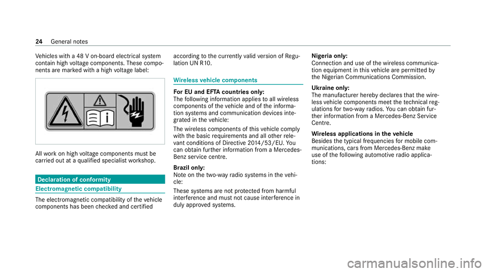
Ve
hicles with a 48 V on-board electrical sy stem
conta in high voltage components. These compo‐
nents are mar ked with a high voltage label: All
workon high voltage components must be
car ried out at a qualified specialist workshop. Declaration of conformity
Electromagnetic compatibility
The electromagnetic compatibility of
theve hicle
components has been checked and certified according
tothe cur rently valid version of Regu‐
lation UN R10. Wire
lessvehicle comp onents Fo
r EU and EF TAcount ries onl y:
The following information applies toall wireless
components of theve hicle and of the informa‐
tion sy stems and communication devices inte‐
grated in theve hicle:
The wireless components of this vehicle comply
with the basic requ irements and all other rele‐
va nt conditions of Directi ve2014 /53/EU. Yo u
can obtain fur ther information from a Mercedes-
Benz service cent re.
Brazil on ly:
No teon the two-w ayradio sy stems in theve hi‐
cle:
These sy stems are not pr otected from harmful
inter fere nce and mu stnot cause inter fere nce in
duly appr oved sy stems. Nigeria onl
y:
Connection and use of the wireless communica‐
tion equipment in this vehicle are permitted by
th e Nigerian Communications Commission.
Ukraine onl y:
The manufacturer hereby declares that the wire‐
less vehicle components meet thete ch nical reg‐
ulations for two-w ayradios. You can obtain fur‐
th er information from a Mercedes-Benz Service
Centre.
Wire less applications in theve hicle
Besides the typical frequencies for mobile com‐
munications, cars from Mercedes-Benz make
use of thefo llowing automotive radio applica‐
tions: 24
General no tes
Page 77 of 469
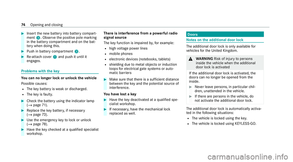
#
Insert the new battery into battery compart‐
ment 3. Obser vethe positive pole marking
in the battery compartment and on the bat‐
te ry when doing this. #
Push in battery compartment 3.#
Re-attach co ver1 and push it until it
engages. Problems with
thekey Yo
u can no lon ger lo ckor unlock theve hicle
Po ssible causes:
R The key bat tery iswe ak or dischar ged.
R The key is faulty. #
Check the battery using the indicator lamp
(/ page 71). #
Replace theke y bat tery, if necessary
(/ page 73). #
Use the emer gency keyto lock or unlock
(/ page 78). #
Have theke ych ecked at a qualified specialist
wo rkshop. There is inter
fere nce from a po werful radio
signal source
The key function is impaired by,fo rex ample:
R high voltage po wer lines
R mobile phones
R electronic devices (no tebooks, tablets)
R shielding due tome tal objects or induction
loops for electrical gatesystems or auto‐
matic bar riers #
Make sure that there is a suf ficient di stance
between theke y and the po tential sou rce of
inter fere nce.
Yo u ha velost a key #
Have theke y deacti vated at a qualified spe‐
cialist workshop. #
If necessar y,ha ve the mechanical lock
re placed as well. Doors
Note
s onthe additional door lock The additional door lock is only
available for
ve hicles forth eUni ted Kingdom. &
WARNING Risk of inju ryto persons
inside theve hicle when the additional
door lock is activated
If th e additional door lock is activated, the
doors can no longer be opened from the
inside. #
Never lea vepersons, in particular chil‐
dren, unat tended in theve hicle. #
Ifth ere are persons in theve hicle, do
not activate the additional door loc k. The additional door lock is automatically activa‐
te d in thefo llowing situations:
R The vehicle is loc ked using thekey.
R The vehicle is loc ked using KEYLESS-GO. 74
Opening and closing
Page 80 of 469

There is in
terference from a po werful radio
signal source
The KEYLESS-GO function is impaired by,for
ex ample:
R high voltage po wer lines
R mobile phones
R electronic devices (No tebooks, Tablets)
R shielding due tome tal objects or induction
loops for electrical gate systems or auto‐
matic bar riers #
Make sure that there is a suf ficient di stance
between theke y and the po tential sou rce of
inter fere nce. Ac
tivating/deactivating the automatic lo ck‐
ing feature The
vehicle is loc ked automatically when the
ignition is switched on and the wheels are turn‐
ing fast erthan walking pace. #
Toactivate: press and hold button 2for
appr oximately five seconds until an acoustic
signal sounds. #
Todeactivate: press and hold button 1for
appr oximately five seconds until an acoustic
signal sounds. In
thefo llowing situations, there is a danger of
being loc ked out when the function is activated:
R While theve hicle is being tow star ted/
pushed.
R Ifth eve hicle is being tested on a roller dyna‐
mome ter. Po
we r closing function &
WARNING Risk of becoming trapped
when the doors close automatically
Body parts or objects can become trapped,
causing injuries. #
Ensure that no body parts or objects
are in the closing area. #
Automatic closing of the doors can be
cancelled bypulling the outer or inner
door handle. If
yo u push the door into the lock tothefirst
de tent position, the po wer closing function will
auto matical lypull the door into the loc k. Opening and closing
77
Page 121 of 469
not be able
tobe charge d or connec ted with
th eve hicle's exterior aerial.
R The mobile phone may heat up during the
ch arging process. This may particular ly
depend on the applications (apps) cur rently
open in the bac kground.
R Toensure more ef ficient charging and con‐
nection with theve hicle's exterior aerial,
re mo vethe pr otective co ver from the mobile
phone. Pr otective co vers which are neces‐
sary for wireless charging are excluded.
R When charging, the mat should be used if
possible. Wire
lessly charging a mobile phone Requ
irements:
R The mobile phone is suitable for wireless
ch arging (Qi-compatible mobile phone).
A list of Qi-compatible mobile phones can be
fo und at: https://www.mercedes-benz-
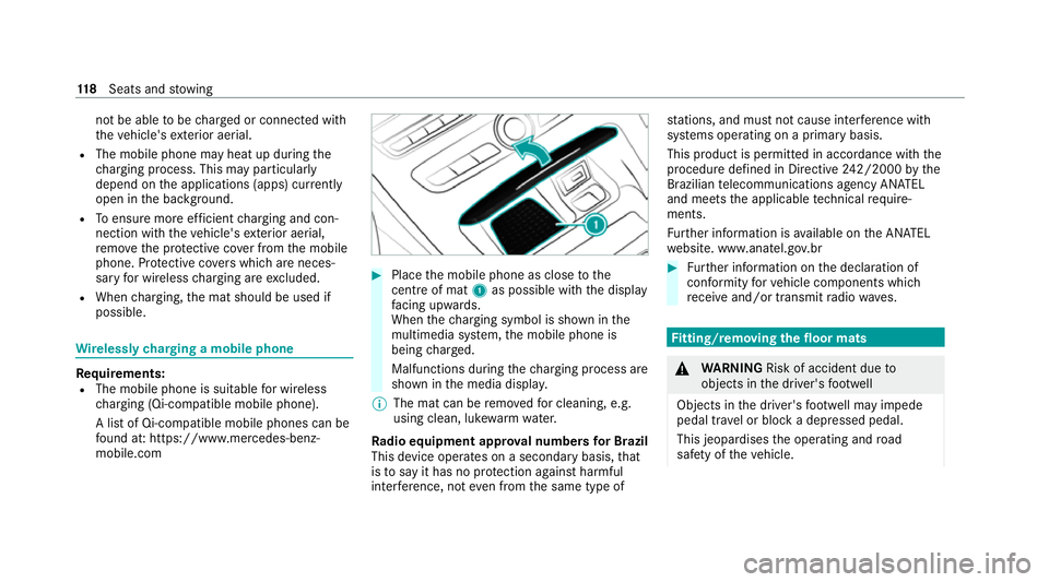
mobile.com #
Place the mobile phone as close tothe
centre of mat 1as possible wi th the display
fa cing up wards.
When thech arging symbol is shown in the
multimedia sy stem, the mobile phone is
being charge d.
Malfunctions during thech arging process are
shown in the media displa y.
% The mat can be remo vedfo r cleaning, e.g.
using clean, luk ewarmwate r.
Ra dio equipment appr oval numbers for Brazil
This device operates on a secondary basis, that
is to say it has no pr otection against harmful
inter fere nce, not even from the same type of st
ations, and must not cause inter fere nce wi th
sy stems operating on a primary basis.
This product is permitted in accordance with the
procedure defined in Directive 242/2000 bythe
Brazilian telecommunications agency AN ATEL
and meets the applicable tech nical requ ire‐
ments.
Fu rther information is available on the AN ATEL
we bsite. www.anatel.go v.br #
Further information on the declaration of
confo rmity forve hicle components which
re cei veand/or transmit radio wav es. Fi
tting/ removing the floormats &
WARNING Risk of accident due to
objects in the driver's foot we ll
Objects in the driver's foot we ll may impede
pedal tr avel or block a depressed pedal.
This jeopardises the operating and road
saf ety of theve hicle. 11 8
Seats and stowing
Page 138 of 469
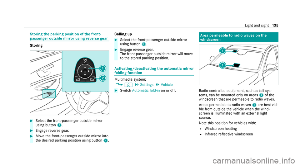
St
oring the pa rking position of the front-
passenger outside mir ror using reve rsege ar St
oring #
Select the front-passen ger outside mir ror
using but ton2. #
Engage reve rsege ar. #
Movethe front-passen ger outside mir ror into
th e desired parking position using button 1.Calling up #
Select the front-passen ger outside mir ror
using but ton2. #
Engage reve rsege ar.
The front-passenger outside mir ror will mo ve
to thestored parking position. Ac
tivating/deactivating the automatic mir ror
fo lding function Multimedia sy
stem:
4 © 5
Settings 5
Vehicle #
Switch Automatic fold-in on or off. Area permeable
to radiowav es on the
windscreen Ra
dio-contro lled equipment, such as toll sys‐
te ms, can be mounted only on areas 1ofthe
windscreen that are permeable toradio wav es.
Areas permeable toradio wav es1 are best visi‐
ble from outside theve hicle when the wind‐
screen is illuminated with an extern al light
source.
No tethis position forve hicles with:
R Windsc reen heating
R Infra redre flective windscreen Light and sight
13 5
Page 248 of 469
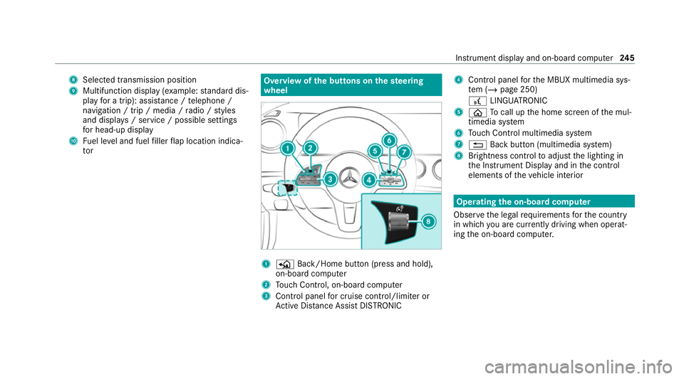
8
Selected transmission position
9 Multifunction displ ay(exa mp le:standard dis‐
play for a trip): assi stance / telephone /
navigation / trip / media / radio / styles
and displa ys/ service / possible settings
fo r head-up display
A Fuel le vel and fuel filler flap location indica‐
tor Overview of
the but tons on thest eering
wheel 1
P Back/Home button (press and hold),
on-board computer
2 Touch Control, on-board co mputer
3 Control panel for cruise control/limiter or
Ac tive Dis tance Assi stDISTRONIC 4
Control panel forth e MBUX multimedia sys‐
te m (/ page 250)
£ LINGU ATRO NIC
5 ò Tocall up the home screen of the mul‐
timedia sy stem
6 Touch Control multimedia sy stem
7 % Back button (multimedia sy stem)
8 Brightness control toadjust the lighting in
th e Instrument Display and in the control
elements of theve hicle interior Operating
the on-boa rdcompu ter
Obser vethe legal requ irements forth e count ry
in which you are cur rently driving when operat‐
ing the on-board computer. Instrument display and on-board computer
245
Page 249 of 469
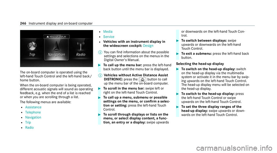
The on-board computer is operated using
the
left-hand Touch Control and the left-hand back/
home button.
When the on-board computer is being operated,
dif fere nt acoustic signals will sound as operating
fe edbac k,e.g. when the end of a list is reached
or when you are sc rolling thro ugh a list.
The following menus are available:
R Assistance
R Telephone
R Navigation
R Trip
R Radio R
Media
R Service
R Vehicles with an instrument display in
th e widescreen cockpit: Design
% You can find information about the possible
settings and selections on the menus in the
Digital Owner's Manual. #
Tocall up the menu bar: pressthe left-hand
back button until the menu bar is displa yed.
% Ve
hicles without Active Di stance Assist
DISTRO NIC:press theò button tocall
up the menu bar of the on-board computer. #
Toscroll in the menu bar: swipe left or
ri ght on the left-hand Touch Control. #
Tocall up a menu, submenu or possible
settings on the menu, or confirm a selec‐
tion or setting: pressthe left-hand Touch
Control. #
Toscroll through displa ysor lists on the
menu, or select display content, a func‐
tion, an entry or a displa y:swipe upwards or down
wards on the left-hand Touch Con‐
trol. #
Toswitch between displa ys:swipe
upwards or down wards on the left-hand
To uch Control. #
Toexit a submenu: pressthe left-hand back
button.
Selecting the head-up display #
Toswitch on the head-up displa y:switch
on the head-up display via the multimedia
sy stem or activate it in the menu bar byswip‐
ing upwards on the left-hand Touch Control.
The head-up displ aymenu will be selected on
th e head-up displa y. #
Toswitch tothe head-up displa y:press
th e left-hand Touch Control or swipe
upwards on the left-hand Touch Control. #
Toset theth ree display ranges of the
head-up displa y:swipe upwards or down‐
wa rds on the left-hand Touch Control. 246
Instrument display and on-board computer