2020 MERCEDES-BENZ C-CLASS ESTATE light
[x] Cancel search: lightPage 241 of 565
Specifying
thest arting point for the warning
to nes
Yo u can specify whe ther thePa rking Assist
PA RKTRONIC warning tones should commence
when theve hicle is fur ther aw ay from an obs ta‐
cle. #
Select Warn early. #
Activate Oor deacti vate ª the function.
Ac tivating/deactivating audio fadeout
Yo u can specify whe ther thevo lume of a media
source in the multimedia sy stem is tobe
re duced when Parking Assist PARKTRONIC gives
an audible warning. #
Select Audio fadeout during warning tones .#
Activate Oor deacti vate ª the function. Ac
tive Parking Assist Fu
nction of Active Parking Assist
% The availability of this function is dependent
on the count ry.
Ac tive Parking Assist is an electro nic parking
assis tance sy stem, which uses ultrasound with th
e assis tance of there ve rsing camera and 360°
Camera. When you are driving forw ards up to
appr oximately 35 km/h, the sy stem automati‐
cally measures parking spaces on bo thsides of
th eve hicle.
As soon as all requ irements are met for sear ch‐
ing for parking spaces, theÇ display appears
in the multifunction displa y.
When Active Parking Assist has de tected park ing
spaces, theÈ display appears in the multi‐
function displa y.The ar rowsshow on which side
of thero ad de tected park ing spaces are located.
They are then shown in the media displa y.
The parking space can be selected as desired.
Depending on the location of the parking space,
th e parking direction (rear wards or forw ards)
can also be selec ted as desired.
When Active Parking Assist is activated, the turn
signal indicators are activated based on the cal‐
culated path of your vehicle.
When you are en tering or exiting a parking
space, the procedure is assis tedby acceleration,
braking, steering and gear changes. Ac
tive Parking Assist is only an aid. It is not a
substitute foryo ur attention tothe sur roundings.
The responsibility for safe manoeuvring and
parking remains with you. Make sure that no
persons, animals or objects etc. are in the
manoeuvring range.
Ac tive Parking Assist will be cancelled in thefo l‐
lowing situations:
R Parking Assist PARKTRONIC is deacti vated.
R You begin steering.
R You apply the parking brake.
R You en gage transmission position j.
R ESP ®
inter venes.
R You open the doors or theta ilgate while driv‐
ing.
Sy stem limits
If th eex terior lighting is malfunctioning, Active
Pa rking Assist is not available.
Objects located abo veor below the de tection
ra nge of the sensors, e.g. overhanging loads,
ov erhangs or loading ramp s of goods vehicles, or
th e borders of parking spaces, are not de tected
du ring measu rement of the parking space. These 238
Driving and parking
Page 247 of 565
*
NO
TEPlug-in hybrid #
Obser vethe no tes in the Supplement.
Yo u could otherwise failto recognise
dangers. Obser
vethefo llowing no tes on theto ngue
we ight:
R Do not use a tongue weight that exceeds or
fa lls below the permissible tongue weight
R Use a tongue weight as close as possible to
th e maximum tongue weight
Do not exceed thefo llowing values:
R Perm issible towing capacity
R Perm issible rear axle load of theto wing vehi‐
cle
R Perm issible gross weight of theto wing vehi‐
cle
R Perm issible grossweight of the trailer
R Maximum permissible speed of the trailer Ensure
thefo llowing before starting a journey:
R The tyre pressure on there ar axle of theto w‐
ing vehicle is set for a maximum load
R The lighting of the connected trailer is opera‐
tional
R Vehicles without LED headlamps or MUL‐
TIBEAM LED headlamps: the headlamps
ha ve been set cor rectly
In theeve nt of increased rear axle load, the car/
trailer combination must not exceed a maximum
speed of 100 km/h forre asons concerning the
operating permit. This also applies in countri es
in which the permissible maximum speed for
car/trailer combinations is above 100 km/h. Fo
lding the ball neck out and in &
WARNING Risk of accident due tothe
ball neck not being engaged
If th e ball neck is not engaged, the trailer
may come loose. #
Alw ays engage the ball neck as descri‐
bed. &
WARNING Risk of injury from ball neck
swinging outwards
The ball neck may swing outwards when
unlo cking or when it has not been properly
engaged.
There is a risk of injury within the ball neck's
ra nge of mo vement! #
Unlock the ball neck only when its
ra nge of mo vement is unobstructed. #
Alw ays be sure the ball neck is engaged
when folding in wards. Re
quirements:
R The vehicle is secured against rolling away.
R The swivel range is clear.
R The trailer cables or adap ter plugs ha vebeen
re mo ved. 244
Driving and pa rking
Page 249 of 565
Coupling/uncoupling a trailer
&
WARNING Risk of injury fromtheve hicle
le ve l being changed
Ve hicles with le vel control sy stem: the
ve hicle le vel may be changed unin tentional ly,
e.g. by ot her persons. You may become trap‐
ped if you couple up or uncouple a trailer
while theve hicle le vel is changing. In addi‐
tion, other people could become trapped if
th eir limbs are between theve hicle body and
th e tyres or underneath theve hicle.
When coupling up or uncoupling a trailer,
make sure that: #
The doors or tailgate are not opened or
closed. #
You do not initiate the le vel control sys‐
te m and do not operate theDY NA MIC
SELECT switch. #
Do not lock or unlock theve hicle. Re
quirements:
R The ball neck is extended and engaged in a
secu rely loc ked position. Tr
ailers with a 7-pin plug can be connec tedto
th eve hicle with thefo llowing adap ters:
R Adapter plug
R Adapter cable
The trailer will be cor rectly de tected bytheve hi‐
cle only if thefo llowing conditions are me t:
R The trailer is connected cor rectl y.
R The trailer lighting sy stem is in working
order.
The functions of thefo llowing sy stems will be
af fected bya cor rectly connected trailer:
R ESP ®
trailer stabilisation
R Active Lane Keeping Assist
R Parking Assist PARKTRONIC
R Active Parking Assist
R Blind Spot Assist or Active Blind Spot Assi st
R Drive AwayAssi st
R Cross Traf fic Alert
R Reversing camera
R 360° camera R
AIRMATIC
Coupling up a trailer
* NO
TEDama getothest ar ter battery due
to full discharge Charging
the trailer battery using the po wer
supply of the trailer can damage thest ar ter
batter y. #
Do not use theve hicle's po wer supply
to charge the trailer batter y. #
Remo vethe co ver cap from the ball head and
st ore it in a safe place. #
Position the trailer on a le vel sur face behind
th eve hicle and couple it up totheve hicle. 246
Driving and pa rking
Page 250 of 565
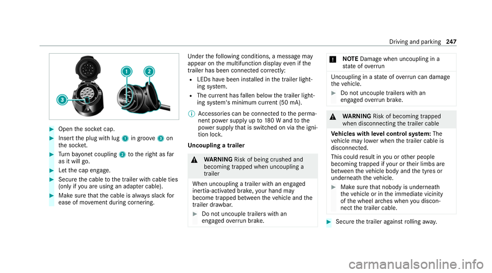
#
Open the soc ket cap. #
Inse rtthe plug with lug 1in groo ve3 on
th e soc ket. #
Turn bayonet coupling 2totheright as far
as it will go. #
Let the cap engage. #
Secure the cable tothe trailer with cable ties
(only if you are using an adap ter cable). #
Make sure that the cable is alw ays slack for
ease of mo vement during cornering. Under
thefo llowing conditions, a message may
appear on the multifunction display even if the
trailer has been connected cor rectly:
R LEDs ha vebeen ins talled in the trailer light‐
ing sy stem.
R The cur rent has fallen below the trailer light‐
ing sy stem's minimum cur rent (50 mA).
% Accessories can be connected tothe perma‐
nent po wer supp lyup to180 W and tothe
po we r supp lythat is swit ched on via the igni‐
tion loc k.
Un coupling a trailer &
WARNING Risk of being crushed and
becoming trapped when uncoupling a
trailer
When uncoupling a trailer with an engaged
ine rtia-activated brake, your hand may
become trapped between theve hicle and the
trailer dr awbar. #
Do not uncouple trailers with an
engaged overrun brake. *
NO
TEDama gewhen uncoupling in a
st ate of overrun Uncou
pling in a state of overru n can dama ge
th eve hicle. #
Do not uncouple trailers with an
engaged overrun brake. &
WARNING Risk of becoming trapped
when disconnecting the trailer cable
Ve hicles with le vel control sy stem: The
ve hicle may lo wer when the trailer cable is
disconnected.
This could result in you or other people
becoming trapped if your or their limbs are
between theve hicle body and the tyres or
underneath theve hicle. #
Make sure that nobody is unde rneath
th eve hicle or in the immediate vicinity
of the wheel ar ches when you discon‐
nect the trailer cable. #
Secure the trailer against rolling away. Driving and pa
rking 247
Page 255 of 565
7
Selected transmission position
8 Multifunction displ ay(exa mp le:standard dis‐
play for a trip): assi stance / telephone /
navigation / trip / media / radio / styles
and displa ys/ service / possible settings
fo r head-up display
9 Fuel le vel and fuel filler flap location indica‐
tor Overview of buttons on
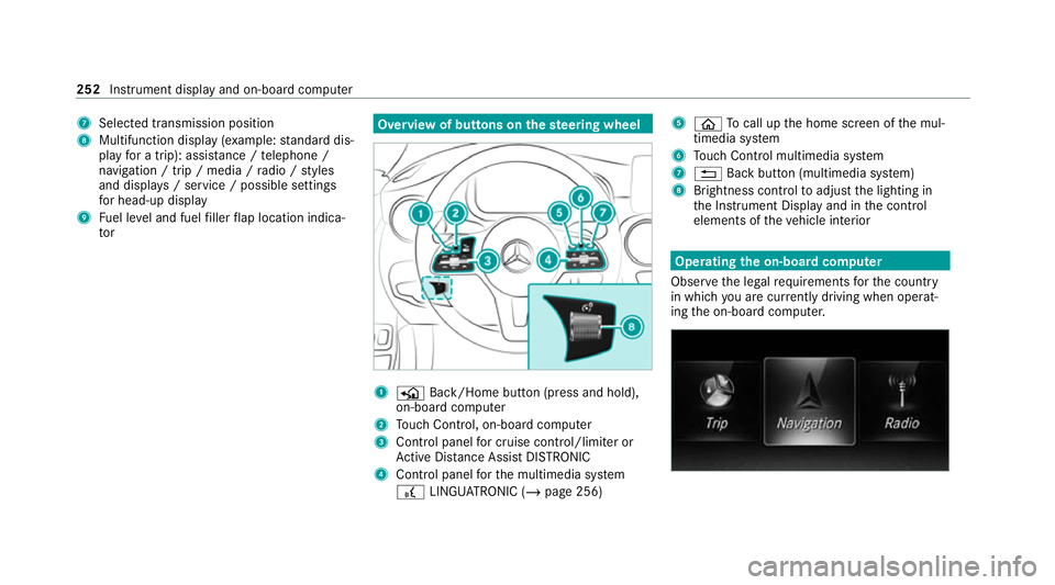
thest eering wheel 1
P Back/Home button (press and hold),
on-board computer
2 Touch Control, on-board co mputer
3 Control panel for cruise control/limiter or
Ac tive Dis tance Assi stDISTRONIC
4 Control panel forth e multimedia sy stem
£ LINGU ATRO NIC (/ page 256) 5
ò Tocall up the home screen of the mul‐
timedia sy stem
6 Touch Control multimedia sy stem
7 % Back button (multimedia sy stem)
8 Brightness control toadjust the lighting in
th e Instrument Display and in the control
elements of theve hicle interior Operating
the on-boa rdcompu ter
Obser vethe legal requ irements forth e count ry
in which you are cur rently driving when operat‐
ing the on-board computer. 252
Instrument display and on-board computer
Page 257 of 565
è
Active Steering Assist (/ page210)
à Ac
tive Lane Keeping Assist (/ page 222)
è ECO
start/ stop function (/ page168)
ë HOLD fu
nction (/ page 197)
_ Ad
aptive Highbeam Assist (/ page133)
Ad aptive Highbeam Assist Plus
(/ page 135)
ð Maximum pe rmissible speed exceeded
(for cer tain countries only)
Ve hicles with Traf fic Sign Assis t:de tected
instructions and traf fic signs (/ page 217). Head-u
p display Fu
nction of the head-up display *
NO
TEMercedes-AMG vehicles #
Obser vethe no tes in the Supplement.
Yo u could otherwise failto recognise
dangers. The head-up displ
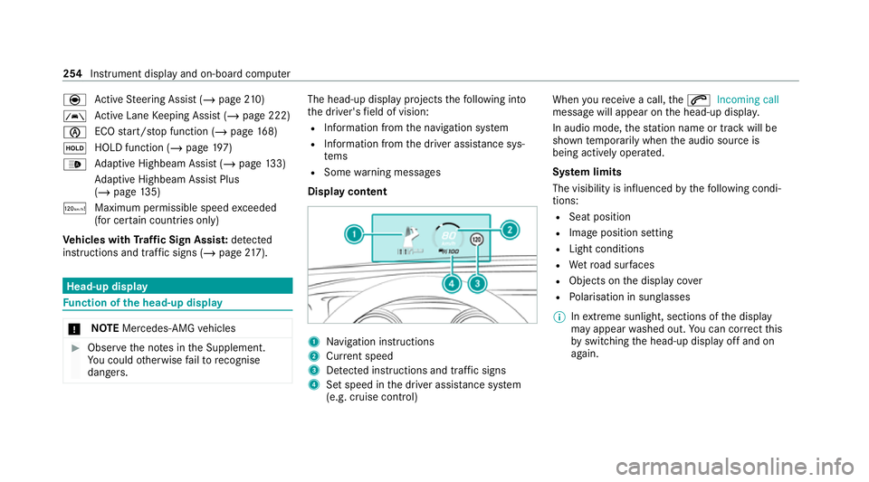
ayprojects thefo llowing into
th e driver's field of vision:
R Information from the navigation sy stem
R Information from the driver assis tance sys‐
te ms
R Some warning messages
Display content 1
Navigation instructions
2 Curr ent speed
3 Detected instructions and traf fic signs
4 Set speed in the driver assis tance sy stem
(e.g. cruise control) When
youre cei vea call, the6 Incoming call
message will appear on the head-up displa y.
In audio mode, thest ation name or track will be
shown temp orarily when the audio source is
being actively operated.
Sy stem limits
The visibility is influenced bythefo llowing condi‐
tions:
R Seat position
R Image position setting
R Light conditions
R Wetro ad sur faces
R Objects on the display co ver
R Polarisation in sunglasses
% Inextreme sunlight, sections of the display
may appear washed out. You can co rrect this
by switching the head-up display off and on
again. 254
Instrument display and on-board computer
Page 271 of 565
Message
voice commands Vo
ice command Function
Text message to
create a message. All address book names are available.
Reply To
reply toa message
Forward text message To
forw ard a message Overview of
vehicle voice commands Yo
u can use theve hicle voice commands to
directly call up the cor responding menus forthe
ve hicle settings.
Ve hicle voice commands Vo
ice command Function
Ambient light menu To
display ambient light settings
Ambient light "blue" To
switch ambient light toblue
Display and styles menu To
show display settings
Assistance menu To
display assis tance settings 268
LINGUATRONIC
Page 272 of 565
Vo
ice command Function
Scent menu To
display fragrance settings
Energy flow To
display energy flow settings
Ionisation menu To
display ionisation settings
Climate control menu To
display climate control settings
Automatic climate control driver on To
switch on the automatic climate control settings on the driver's side
Light menu To
display light settings
Massage menu To
display massage settings
Massage driver's seat on To
switch on the massage function forth e driver's seat
Massage driver's seat off To
switch off the massage function forth e driver's seat
Outside temperature To
display the outside temp erature
Engine data Displaying engine data
Seats menu To
display seat adjustment settings
Seat heating front passenger level "2" To
set the seat heating forth e front passenger seat toleve l 2 LINGU
ATRO NIC 269