2020 MERCEDES-BENZ AMG GT COUPE light
[x] Cancel search: lightPage 297 of 433

R
Only use cleaning agents or cleaning clo ths
th at are suitable for plast ic lenses.
Sensors R Clean the sensors in the front and rear
bumpers with a soft clo thand car shampoo
(/ page 127).
R When using a high-pressure cleaner,maintain
a minimum dis tance of 30 cm.
Re versing camera and front camera
R Use clean water and a soft clo thtoclean the
came ralens.
R Do not use a high-pressure cleaner.
Extendable rear wing
R Extend there ar wing when washing byhand
(/ page 143).
R Clean there ar wing with a soft car spon ge
and mild cleaning agent, e.g. car shampoo.
R Retract there ar wing comple tely afte r drying
(/ page 143).
R Do not use a high-pressu recleane r. Ta
ilpipes
R Clean with a cleaning agent recommended
fo r Mercedes-Benz, especially inthe winter
and af terwa shing theve hicle.
R Do not use acidic cleaning agents. Note
s on care of the interior &
WARNING Risk of injury from plastic
parts breaking off af terth e use of sol‐
ve nt-based care products
Ca reand cleaning products con taining sol‐
ve nts can cause su rfaces in the cockpit to
become porous. When the airbags are
deplo yed, plastic parts may break away. #
Do not use any care or cleaning prod‐
ucts containing sol vents toclean the
cockpit. &
WARNING Risk of injury or death from
bleached seat belts
Bleaching or dyeing seat belts can se verely
we aken them. This can,
forex ample, cause seat belts to
te ar or fail in an accident. #
Never blea chor dye seat belts. Obser
vethe no tes on cleaning and care toavo id
ve hicle damage.
Seat belts R Clean with luk ewarmand soapy water.
R Do not use chemical cleaning agents.
R Do not dry seat belts byheating them toover
80 °C or exposing them todirect sunlight.
Display
R Switch off the display and let it cool down.
R Clean the sur face carefully with a microfibre
clo thand a suitable display care product
(TFT/LCD).
R Do not use any other agents.
Plastic trim
R Clean with a damp microfibre clo th.
R For heavy soiling: use a care product recom‐
mended for Mercedes-Benz. 294
Maintenance and care
Page 309 of 433
#
Only use battery charge rs with a maxi‐
mum charging voltage of 14.8 V. &
WARNING Risk ofexplosion during
ch arging process and starting assis tance
During thech arging process and starting
assis tance, the battery may release an explo‐
sive gas mixture. #
Avoid fire , naked flames, creating
spar ksand smoking. #
Make sure there is suf ficient ventila‐
tion. #
Do not lean over a batter y. &
WARNING Risk ofexplosion from a fro‐
zen battery
A dischar ged battery may freeze at temp era‐
tures slightly abo veor below freezing point.
During starting assis tance or battery charg‐
ing, bat tery gas can be released. #
Alw ays allow a battery tothaw before
ch arging it or per form ing starting assis‐
ta nce. If
th e indicator/warning lamps in the instrument
clus ter do not light up at low temp eratures, it is
ve ry likely that the dischar ged battery has fro‐
zen. In this case you may neither jump-s tart the
ve hicle nor charge the batter y.
The service life of a battery that has been
th awe d may be dramatically shor tened. The
st arting characteristics may be impaired, espe‐
cially at low temp eratures.
It is recommended that you ha veathaw ed bat‐
te ry checked at a qualified specialist workshop.
* NO
TEDama gecaused bynumerous or
ex tended attempt sto start the engine Nume
rous or extended attempt sto start the
engine may damage the catalytic con verter
due tonon-combu sted fuel. #
Avoid numerous and extended attem pts
to start the engine. Obser
vethefo llowing points during starting
assis tance and when charging the battery:
R Only use undamaged jump lead/charging
cables with a suf ficient cross-section and
insula tedte rm inal clamps.
R Non- insulated parts of thete rm inal clamps
must not come into con tact with other me tal
parts while the jump lead/charging cable is
connected tothe battery/jump-s tart connec‐
tion point.
R The jump lead/charging cable must not
come into contact wi thany parts which may
mo vewhen the engine is running.
R Alw ays make sure that nei ther you nor the
battery is elect rostatically charge d.
R Keep away from fire and naked flames.
R Do not lean overth e batter y.
R Take care that the positive term inal of a con‐
nec ted battery does not come into con tact
wi th vehicle parts.
R Never place me tal objects or tools on a bat‐
te ry. 306
Breakdown assis tance
Page 311 of 433
with positive clamp
2onyour ow nve hicle
fi rs t. #
During starting assi stance: start the
engine of the donor vehicle and run at idle
speed. #
Connect the negative pole of the donor bat‐
te ry and ear thpoint 3ofyour ow nve hicle
by using the jump lead/charging cable. Begin
with the donor battery firs t. #
During starting assi stance: start the
engine of your ow nve hicle. #
During thech arging process: start the
ch arging process. #
During starting assi stance: letthe engines
ru nfo r se veral minutes. #
During starting assi stance: before discon‐
necting the jump lead, switch on an electrical
consumer in your ow nve hicle, e.g. there ar
wind owheater or lighting.
When thest arting assis tance/charging process
is compl ete, per form thefo llowing steps: #
First,re mo vethe jump lead/charging cable
from ear thpoint 3and the negative pole of
th e donor batter y,then from positive clamp
2 and the positive pole of the donor bat‐
te ry. Begin ea chtime wi th the conta cts on
yo ur ow nve hicle firs t. #
Afterre moving the jump lead/charging
cable, close co ver1 of positive clamp 2.
Fu rther information can be obtained at a quali‐
fi ed specialist workshop. Re
placing the 12V battery #
Obser vethe no tes on the12 V battery
(/ page 304).
Mercedes-Benz recommends that you ha vethe
12 V battery replaced at a qualified specialist
wo rkshop, e.g. at a Mercedes-Benz Service
Centre.
If yo uwa nttoreplace the battery yourself,
obse rveth efo llowing no tes:
R Replace a faulty bat tery with a battery which
meets the specific vehicle requ irements. The
vehicle is equipped with a lithium-ion
batter y.Fu llve hicle functionality is only guar‐
anteed with a lithium-ion batter y.Fo r saf ety
re asons, Mercedes-Benz recommends that
yo u on lyuse bat teries which ha vebeen tes‐
te d and appr ovedfo ryo ur vehicle by
Mercedes-Benz.
R Use de tach able parts such as vent hoses,
elbow fittings or term inal co vers from the
battery which is tobe replaced.
R Make sure that theve nt hose is al ways con‐
nected tothe original opening on the side of
th e batter y.
Fit any existing or supplied cell caps.
Otherwise, gases or battery acid could
escape.
R Make sure that de tach able parts are recon‐
nected in the same way. 308
Breakdown assis tance
Page 320 of 433
&
WARNING Risk of accident from repea‐
te d tyre pressure drop
If th e tyre pressure drops repeatedl y,the
wheel, valve or tyre may be damaged.
Insuf ficient tyre pressure can cause the tyres
to bur st. #
Inspect the tyre for signs of fore ign
objects. #
Check whe ther the wheel or valve has a
leak. #
Ifyo u are unable torectify the damage,
conta ct aqualified specialist workshop. Information on
there commended tyre pressure
fo rth eve hicle's factor y-fitted tyres can be found
on the tyre pressure table on the inside of the
fuel filler flap (/ page317).
Use a suita ble pressure gauge tocheck the tyre
pressure. The outer appearance of a tyre does
not permit any reliable conclusion about the tyre
pressure. Only cor
rect tyre pressures when the tyres are
cold. Conditions for cold tyres:
R The vehicle has been par ked with the tyres
out of direct sunlight for at least thre e hours.
R The vehicle has tr avelled less than 1.6 km.
The vehicle's tyres heat up when driving. As the
te mp erature of the tyres increases, so too does
th e tyre pressure.
Ve hicles with a tyre pressure monitoring sys‐
te m: you can also check the tyre pressure using
th e on-board computer. Ty
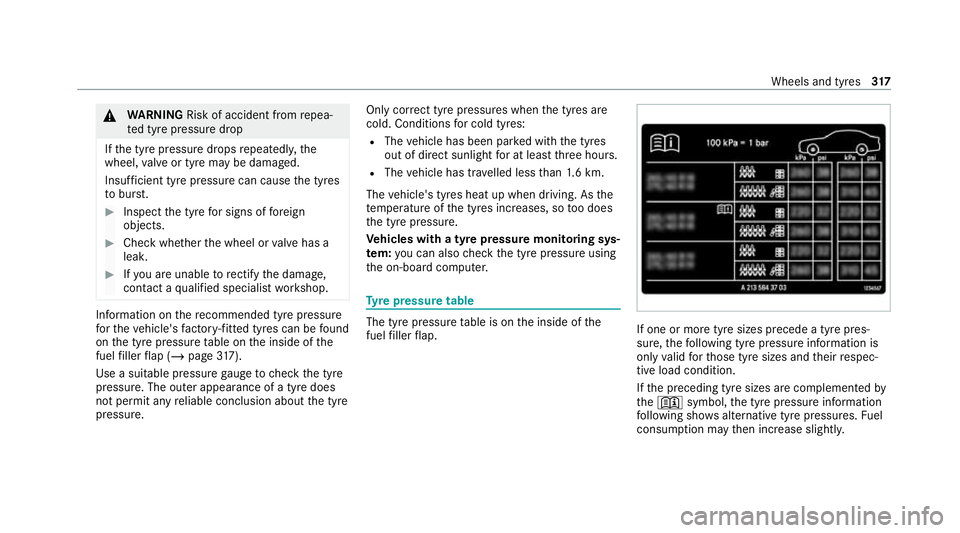
re pressure table The tyre pressure
table is on the inside of the
fuel filler flap. If one or more tyre sizes precede a tyre pres‐
sure,
thefo llowing tyre pressure information is
only valid forth ose tyre sizes and their respec‐
tive load condition.
If th e preceding tyre sizes are complemented by
th e+ symbol, the tyre pressure information
fo llowing sho wsalternative tyre pressures. Fuel
consum ption may then increase slightl y. Wheels and tyres
317
Page 334 of 433
#
Make sure on and off switch 4ofthe tyre
inflation compressor is set to0. #
Insert plug 3in a soc ket in your vehicle.
R Cigar ette lighter soc ket
R 12V soc ket (/ page 85).
R Obse rveth e no tes on the cigar ette lighter in
th e Digital Owner's Manual
R Obser vethe no tes on soc kets (/ page 85). #
Press thest art/ stop button once toswitch
on the po wer supp ly. (/ page 100) #
Press On/Off switch 4onthe tyre inflation
compressor toI.
The tyre inflation compressor is switched on.
The tyre is inflated. The tyre pressure is
shown on manome ter5. #
Pump the tyre tothe specified tyre pressure.
% The specified tyre pressure is stated on the
label of the emer gency spa rewheel. #
When the specified tyre pressure has been
re ached, press on and off swit ch4 onthe
tyre inflation compressor to0.
The tyre inflation compressor is switched off. #
Press thest art/ stop button toswitch off the
po we r supp ly. #
Ifth e tyre pressure is higher than the speci‐
fi ed pressure, press pressure release valve
bu tton 6until the cor rect tyre pressure has
been reached. #
Unscr ew union nut 2offiller hose 1from
th eva lve. #
Screw theva lve cap of the emer gency spa re
wheel onto theva lve again. #
Stow filler hose 1and plug 3inthe lo wer
section of the tyre inflation compressor
housing. #
Stow th e tyre inflation compressor in the
ve hicle. Wheels and tyres
331
Page 342 of 433
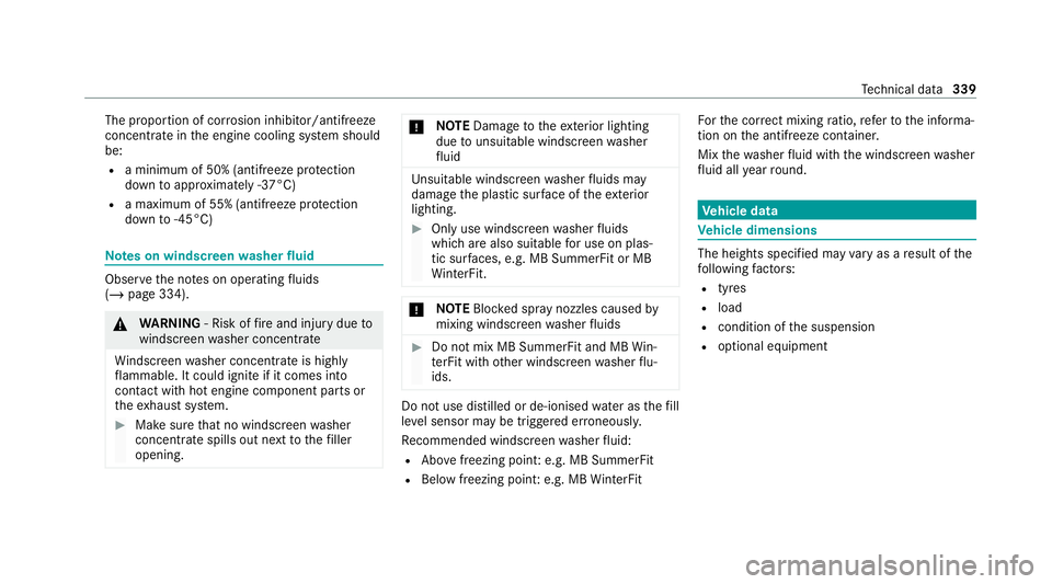
The proportion of cor
rosion inhibitor/antifreeze
concentrate in the engine cooling sy stem should
be:
R a minimum of 50% (antifreeze pr otection
down toappr oximately -37°C)
R a maximum of 55% (antifreeze pr otection
down to-45°C) Note
s on windscreen washer fluid Obser
vethe no tes on operating fluids
(/ page 334). &
WARNING ‑ Risk of fire and injury due to
windscreen washer concentrate
Wi ndsc reen washer concentrate is highly
fl ammable. It could ignite if it comes into
con tact with hot engine component parts or
th eex haust sy stem. #
Make sure that no windscre enwasher
concentrate spills out next tothefiller
opening. *
NO
TEDama getotheex terior lighting
due tounsuitable windsc reen washer
fl uid Uns
uitable windsc reen washer fluids may
damage the plastic sur face of theex terior
lighting. #
Only use windscreen washer fluids
which are also suitable for use on plas‐
tic sur faces, e.g. MB SummerFit or MB
Wi nterFit. *
NO
TEBlocked spr aynozzles caused by
mixing windscreen washer fluids #
Do not mix MB SummerFit and MB Win‐
te rFit with other windscreen washer flu‐
ids. Do not use distilled or de-ionised
water asthefill
le ve l sensor may be triggered er roneously.
Re commended windscreen washer fluid:
R Abo vefreezing point: e.g. MB SummerFit
R Below freezing point: e.g. MB WinterFit Fo
rth e cor rect mixing ratio, referto the informa‐
tion on the antif reeze contai ner.
Mix thewa sher fluid with the windscreen washer
fl uid all year round. Ve
hicle data Ve
hicle dimensions The heights specifi
ed mayvary as a result of the
fo llowing factors:
R tyres
R load
R condition of the suspension
R optional equipment Te
ch nical da ta339
Page 351 of 433

Lights
Display messages
Possible causes/consequences and M MSolutions
: Left dipped beam (examp le) *T
he cor responding light source is defective. #
Drive on carefully. #
Consult a qualified specialist workshop immediatel y.
% LED light sources: the display message forth e cor responding light appears only when allthe light-emitting
diodes in the light are faulty.
: Malfunction See Owner's
Manual *T
heexterior lighting is malfunctioning. #
Consult a qualified specialist workshop.
: Automatic driving lights
inoperative *T
he light sensor is malfunctioning. #
Consult a qualified specialist workshop. 348
Displaymessa ges and warning/indicator lamps
Page 352 of 433
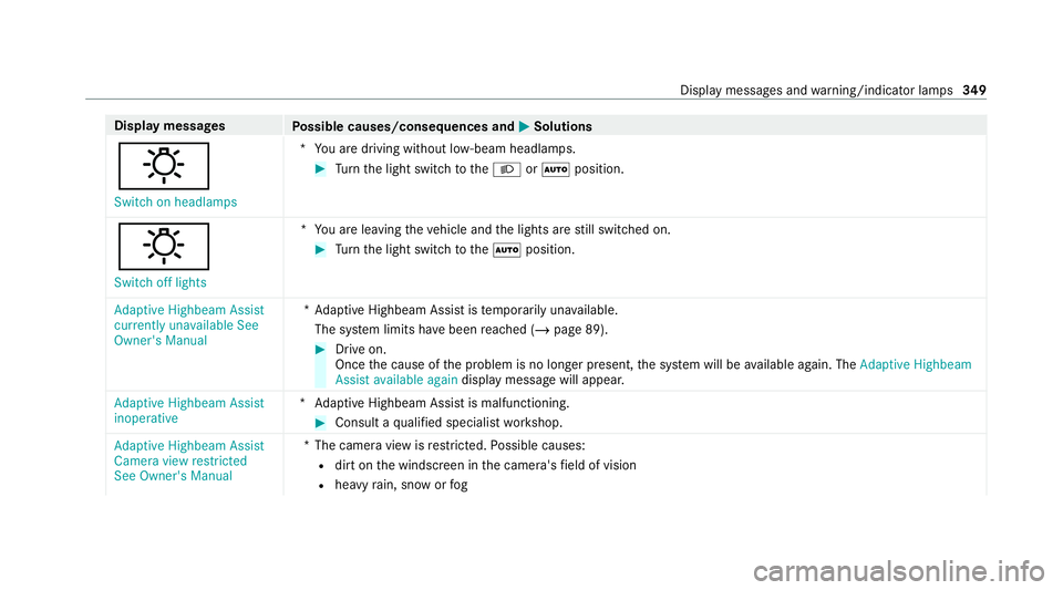
Display messages
Possible causes/consequences and M MSolutions
: Switch on headlamps *Y
ou are driving without lo w-beam headlamps. #
Turn the light switch totheL orà position.
:
Switch off lights *Y
ou are leaving theve hicle and the lights are still switched on. #
Turn the light switch totheà position.
Adaptive Highbeam Assist
currently unavailable See
Owner's Manual *A
daptive Highbeam Assist is temp orarily una vailable.
The sy stem limits ha vebeen reached (/ page 89). #
Drive on.
Once the cause of the problem is no longer present, the sy stem will be available again. The Adaptive Highbeam
Assist available again display message will appear.
Adaptive Highbeam Assist
inoperative *A
daptive Highbeam Assist is malfunctioning. #
Consult a qualified specialist workshop.
Adaptive Highbeam Assist
Camera view restricted
See Owner's Manual *T
he camera view is restricted. Possible causes:
R dirt on the windscreen in the camera's field of vision
R heavy rain, snow or fog Displ
aymessa ges and warning/indicator lamps 349