2020 CHRYSLER 300 tow
[x] Cancel search: towPage 105 of 328

SAFETY103
The BSM system detection zone DOES NOT
change if your vehicle is towing a trailer.
Therefore, visually verify the adjacent lane is
clear for both your vehicle and trailer before
making a lane change. If the trailer or other
object (i.e., bicycle, sports equipment)
extends beyond the side of your vehicle, this
may result in the BSM warning light randomly
alerting on the trailer or even remaining illu -
minated the entire time the vehicle is in a
forward gear.
The Blind Spot Monitoring (BSM) system may
experience drop outs (blinking on and off) of
the side mirror Warning Indicator lamps
when a motorcycle or any small object
remains at the side of the vehicle for
extended periods of time (more than a couple
of seconds).
The area on the rear fascia where the radar
sensors are located must remain free of snow,
ice, and dirt/road contamination so that the
BSM system can function properly. Do not block
the area of the rear fascia where the radar
sensors are located with foreign objects
(bumper stickers, bicycle racks, etc.).
Sensor Location (Driver Side Shown)
The BSM system notifies the driver of objects in
the detection zones by illuminating the BSM
warning light located in the outside mirrors in
addition to sounding an audible (chime) alert
and reducing the radio volume if the
corresponding turn signal is activated. Refer to
“Modes Of Operation” for further information.
The BSM system monitors the detection zone
from three different entry points (side, rear,
front) while driving to see if an alert is
necessary. The BSM system will issue an alert
during these types of zone entries.
Entering From The Side
Vehicles that move into your adjacent lanes
from either side of the vehicle.
Side Monitoring
Entering From The Rear
Vehicles that come up from behind your vehicle
on either side and enter the rear detection zone
with a relative speed of less than 31 mph
(50 km/h).
Rear Monitoring
4
20_LX_OM_EN_USC_t.book Page 103
Page 107 of 328

SAFETY105
Rear Cross Path (RCP) - If Equipped
The Rear Cross Path (RCP) feature is intended
to aid the driver when backing out of parking
spaces where their vision of oncoming vehicles
may be blocked. Proceed slowly and cautiously
out of the parking space until the rear end of the
vehicle is exposed. The RCP system will then
have a clear view of the cross traffic and if an
oncoming vehicle is detected, alert the driver.
RCP Detection Zones
RCP monitors the rear detection zones on both
sides of the vehicle, for objects that are moving
toward the side of the vehicle with a minimum
speed of approximately 3 mph (5 km/h), to
objects moving a maximum of approximately
20 mph (32 km/h), such as in parking lot
situations. NOTE:
In a parking lot situation, oncoming vehicles can
be obscured by vehicles parked on either side.
If the sensors are blocked by other structures or
vehicles, the system will not be able to alert the
driver.
When RCP is on and the vehicle is in REVERSE,
the driver is alerted using both the visual and
audible alarms, including reducing the radio
volume.
Modes Of Operation
Three selectable modes of operation are
available in the Uconnect System. Refer to
“Uconnect Settings” in “Multimedia” for further
information.
Blind Spot Alert Lights Only
When operating in Blind Spot Alert mode, the
BSM system will provide a visual alert in the
appropriate side view mirror based on a
detected object. However, when the system is
operating in Rear Cross Path (RCP) mode, the
system will respond with both visual and
audible alerts when a detected object is
present. Whenever an audible alert is
requested, the radio is muted.
Blind Spot Alert Lights/Chime
When operating in Blind Spot Alert Lights/
Chime mode, the BSM system will provide a
visual alert in the appropriate side view mirror
based on a detected object. If the turn signal is
then activated, and it corresponds to an alert
present on that side of the vehicle, an audible
chime will also be sounded. Whenever a turn
signal and detected object are present on the
WARNING!
Rear Cross Path Detection (RCP) is not a back
up aid system. It is intended to be used to
help a driver detect an oncoming vehicle in a
parking lot situation. Drivers must be careful
when backing up, even when using RCP.
Always check carefully behind your vehicle,
look behind you, and be sure to check for
pedestrians, animals, other vehicles,
obstructions, and blind spots before backing
up. Failure to do so can result in serious
injury or death.
4
20_LX_OM_EN_USC_t.book Page 105
Page 117 of 328

SAFETY115
risk of injury caused by striking the inside of the
vehicle. Everyone in a motor vehicle should be
belted at all times.
Enhanced Seat Belt Use Reminder System
(BeltAlert)
Driver and Passenger BeltAlert (if equipped)
BeltAlert is a feature intended to remind the
driver and outboard front seat passenger (if
equipped with outboard front passenger seat
BeltAlert) to buckle their seat belts. The
BeltAlert feature is active whenever the ignition
switch is in the START or ON/RUN position.
Initial Indication
If the driver is unbuckled when the ignition
switch is first in the START or ON/RUN position,
a chime will signal for a few seconds. If the
driver or outboard front seat passenger (if
equipped with outboard front passenger seat
BeltAlert) is unbuckled when the ignition switch
is first in the START or ON/RUN position the
Seat Belt Reminder Light will turn on and
remain on until both outboard front seat belts
are buckled. The outboard front passenger seat
BeltAlert is not active when an outboard front
passenger seat is unoccupied. BeltAlert Warning Sequence
The BeltAlert warning sequence is activated
when the vehicle is moving above a specified
vehicle speed range and the driver or outboard
front seat passenger is unbuckled (if equipped
with outboard front passenger seat BeltAlert)
(the outboard front passenger seat BeltAlert is
not active when the outboard front passenger
seat is unoccupied). The BeltAlert warning
sequence starts by blinking the Seat Belt
Reminder Light and sounding an intermittent
chime. Once the BeltAlert warning sequence
has completed, the Seat Belt Reminder Light
will remain on until the seat belts are buckled.
The BeltAlert warning sequence may repeat
based on vehicle speed until the driver and
occupied outboard front seat passenger seat
belts are buckled. The driver should instruct all
occupants to buckle their seat belts.
Change of Status
If the driver or outboard front seat passenger (if
equipped with outboard front passenger seat
BeltAlert) unbuckles their seat belt while the
vehicle is traveling, the BeltAlert warning
sequence will begin until the seat belts are
buckled again.
The outboard front passenger seat BeltAlert is
not active when the outboard front passenger
seat is unoccupied. BeltAlert may be triggered
when an animal or other items are placed on
the outboard front passenger seat or when the
seat is folded flat (if equipped). It is
recommended that pets be restrained in the
rear seat (if equipped) in pet harnesses or pet
carriers that are secured by seat belts, and
cargo is properly stowed.
BeltAlert can be activated or deactivated by an
authorized dealer. FCA US LLC does not
recommend deactivating BeltAlert.
NOTE:
If BeltAlert has been deactivated and the driver or
outboard front seat passenger (if equipped with
outboard front passenger seat BeltAlert) is
unbuckled the Seat Belt Reminder Light will turn
on and remain on until the driver and outboard
front seat passenger seat belts are buckled.
Lap/Shoulder Belts
All seating positions in your vehicle are
equipped with lap/shoulder belts.
The seat belt webbing retractor will lock only
during very sudden stops or collisions. This
feature allows the shoulder part of the seat belt
4
20_LX_OM_EN_USC_t.book Page 115
Page 120 of 328

118SAFETY
Positioning The Lap Belt
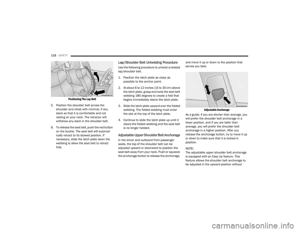
5. Position the shoulder belt across the shoulder and chest with minimal, if any
slack so that it is comfortable and not
resting on your neck. The retractor will
withdraw any slack in the shoulder belt.
6. To release the seat belt, push the red button on the buckle. The seat belt will automat -
ically retract to its stowed position. If
necessary, slide the latch plate down the
webbing to allow the seat belt to retract
fully.
Lap/Shoulder Belt Untwisting Procedure
Use the following procedure to untwist a twisted
lap/shoulder belt.
1. Position the latch plate as close as possible to the anchor point.
2. At about 6 to 12 inches (15 to 30 cm) above the latch plate, grasp and twist the seat belt
webbing 180 degrees to create a fold that
begins immediately above the latch plate.
3. Slide the latch plate upward over the folded webbing. The folded webbing must enter
the slot at the top of the latch plate.
4. Continue to slide the latch plate up until it clears the folded webbing and the seat belt
is no longer twisted.
Adjustable Upper Shoulder Belt Anchorage
In the driver and outboard front passenger
seats, the top of the shoulder belt can be
adjusted upward or downward to position the
seat belt away from your neck. Push or squeeze
the anchorage button to release the anchorage, and move it up or down to the position that
serves you best.
Adjustable Anchorage
As a guide, if you are shorter than average, you
will prefer the shoulder belt anchorage in a
lower position, and if you are taller than
average, you will prefer the shoulder belt
anchorage in a higher position. After you
release the anchorage button, try to move it up
or down to make sure that it is locked in
position.
NOTE:
The adjustable upper shoulder belt anchorage
is equipped with an Easy Up feature. This
feature allows the shoulder belt anchorage to
be adjusted in the upward position without
20_LX_OM_EN_USC_t.book Page 118
Page 140 of 328

138SAFETY
To Install A LATCH-Compatible Child
Restraint
If the selected seating position has a
Switchable Automatic Locking Retractor (ALR)
seat belt, stow the seat belt, following the
instructions below. See the section “Installing
Child Restraints Using the Vehicle Seat Belt” to
check what type of seat belt each seating
position has.
1. Loosen the adjusters on the lower straps
and on the tether strap of the child seat so
that you can more easily attach the hooks
or connectors to the vehicle anchorages.
2. Place the child seat between the lower anchorages for that seating position. If the
second row seat can be reclined, you may
recline the seat and/or raise the head
restraint (if adjustable) to get a better fit. If
the rear seat can be moved forward and
rearward in the vehicle, you may wish to
move it to its rear-most position to make
room for the child seat. You may also move
the front seat forward to allow more room
for the child seat. 3. Attach the lower hooks or connectors of the
child restraint to the lower anchorages in
the selected seating position.
4. If the child restraint has a tether strap, connect it to the top tether anchorage. See
the section “Installing Child Restraints
Using the Top Tether Anchorage” for
directions to attach a tether anchor.
5. Tighten all of the straps as you push the child restraint rearward and downward into
the seat. Remove slack in the straps
according to the child restraint
manufacturer’s instructions.
6. Test that the child restraint is installed tightly by pulling back and forth on the child seat at
the belt path. It should not move more than
1 inch (25.4 mm) in any direction.
How To Stow An Unused Switchable-ALR
(ALR) Seat Belt:
When using the LATCH attaching system to
install a child restraint, stow all ALR seat belts
that are not being used by other occupants or
being used to secure child restraints. An unused
belt could injure a child if they play with it and
accidentally lock the seat belt retractor. Before installing a child restraint using the
LATCH system, buckle the seat belt behind the
child restraint and out of the child’s reach. If the
buckled seat belt interferes with the child
restraint installation, instead of buckling it
behind the child restraint, route the seat belt
through the child restraint belt path and then
buckle it. Do not lock the seat belt. Remind all
children in the vehicle that the seat belts are not
toys and that they should not play with them.
WARNING!
Improper installation of a child restraint to
the LATCH anchorages can lead to failure of
the restraint. The child could be badly
injured or killed. Follow the child restraint
manufacturer’s directions exactly when
installing an infant or child restraint.
Child restraint anchorages are designed to
withstand only those loads imposed by
correctly-fitted child restraints. Under no
circumstances are they to be used for adult
seat belts, harnesses, or for attaching other
items or equipment to the vehicle.
20_LX_OM_EN_USC_t.book Page 138
Page 147 of 328

SAFETY145
(Continued)
PERIODIC SAFETY CHECKS YOU SHOULD
M
AKE OUTSIDE THE VEHICLE
Tires
Examine tires for excessive tread wear and
uneven wear patterns. Check for stones, nails,
glass, or other objects lodged in the tread or
sidewall. Inspect the tread for cuts and cracks.
Inspect sidewalls for cuts, cracks, and bulges.
Check the wheel nuts for tightness. Check the
tires (including spare) for proper cold inflation
pressure.
Lights
Have someone observe the operation of brake
lights and exterior lights while you work the
controls. Check turn signal and high beam
indicator lights on the instrument panel.
Door Latches
Check for proper closing, latching, and locking.
Fluid Leaks
Check area under the vehicle after overnight
parking for fuel, coolant, oil, or other fluid leaks.
Also, if gasoline fumes are detected or if fuel, or
brake fluid leaks are suspected, the cause
should be located and corrected immediately.
ONLY use the passenger’s side floor mat on
the passenger’s side floor area.
ALWAYS make sure objects cannot fall or
slide into the driver’s side floor area when
the vehicle is moving. Objects can become
trapped under accelerator, brake, or clutch
pedals and could cause a loss of vehicle
control.
NEVER place any objects under the floor
mat (e.g., towels, keys, etc.). These objects
could change the position of the floor mat
and may cause interference with the accel -
erator, brake, or clutch pedals.
If the vehicle carpet has been removed and
re-installed, always properly attach carpet
to the floor and check the floor mat
fasteners are secure to the vehicle carpet.
Fully depress each pedal to check for inter -
ference with the accelerator, brake, or
clutch pedals then re-install the floor mats.
WARNING! (Continued)
It is recommended to only use mild soap
and water to clean your floor mats. After
cleaning, always check your floor mat has
been properly installed and is secured to
your vehicle using the floor mat fasteners
by lightly pulling mat.
WARNING! (Continued)
4
20_LX_OM_EN_USC_t.book Page 145
Page 151 of 328

STARTING AND OPERATING149
selector. As an added precaution, always apply
the parking brake when exiting the vehicle.
COLD WEATHER OPERATION (BELOW
–22°F O
R −30°C)
To ensure reliable starting at these
temperatures, use of an externally powered
electric engine block heater (available from an
authorized dealer) is recommended.
IF ENGINE FAILS TO START
If the engine fails to start after you have
followed the "Normal Starting" or "Cold Weather
Operation" procedure, and has not experienced
an extended park condition as identified in
"Extended Park Starting" procedure it may be
flooded. Push the accelerator pedal all the way
to the floor and hold it there. Crank the engine
for no more than 15 seconds. This should clear
any excess fuel in case the engine is flooded.
Leave the ignition key in the RUN position,
release the accelerator pedal and repeat the
“Normal Starting” procedure.
AFTER STARTING
The idle speed is controlled automatically, and
it will decrease as the engine warms up.
ENGINE BLOCK HEATER — IF EQUIPPED
The engine block heater warms the engine, and
permits quicker starts in cold weather. Connect
the cord to a standard 110-115 Volt AC
electrical outlet with a grounded, three-wire
extension cord.
The engine block heater must be plugged in at
least one hour to have an adequate warming
effect on the engine.
The engine block heater cord is routed under
the hood on the driver side of the vehicle. It has
a removable cap that is located near the air box.
WARNING!
Never pour fuel or other flammable liquid
into the throttle body air inlet opening in an
attempt to start the vehicle. This could result
in flash fire causing serious personal injury.
Do not attempt to push or tow your vehicle
to get it started. Vehicles equipped with an
automatic transmission cannot be started
this way. Unburned fuel could enter the
catalytic converter and once the engine has
started, ignite and damage the converter
and vehicle.
If the vehicle has a discharged battery,
booster cables may be used to obtain a
start from a booster battery or the battery in
another vehicle. This type of start can be
dangerous if done improperly. Refer to
“Jump Starting Procedure” in “In Case Of
Emergency” for further information.
CAUTION!
To prevent damage to the starter, do not
continuously crank the engine for more than
25 seconds at a time. Wait 60 seconds
before trying again.
WARNING!
Remember to disconnect the engine block
heater cord before driving. Damage to the
110-115 Volt electrical cord could cause
electrocution.
5
20_LX_OM_EN_USC_t.book Page 149
Page 153 of 328

STARTING AND OPERATING151
(Continued)
(Continued)
When parking on a hill, it is important to turn the
front wheels toward the curb on a downhill
grade and away from the curb on an uphill
grade. Apply the parking brake before placing
the gear selector in PARK, otherwise the load on
the transmission locking mechanism may make
it difficult to move the gear selector out of PARK.
The parking brake should always be applied
whenever the driver is not in the vehicle.
AUTOMATIC TRANSMISSION
WARNING!
Never use the PARK position as a substi -
tute for the parking brake. Always apply the
parking brake fully when parked to guard
against vehicle movement and possible
injury or damage.
When exiting the vehicle, always remove
the key fob from the ignition and lock your
vehicle.
Never leave children alone in a vehicle, or
with access to an unlocked vehicle.
Allowing children to be in a vehicle unat -
tended is dangerous for a number of
reasons. A child or others could be seriously
or fatally injured. Children should be
warned not to touch the parking brake,
brake pedal or the gear selector.
When exiting the vehicle, always make sure
the keyless ignition node is in the OFF
mode, remove the key fob from the vehicle
and lock the vehicle.
Do not leave the key fob in or near the
vehicle or in a location accessible to chil -
dren, and do not leave the ignition of a
vehicle equipped with Keyless Enter-N-Go
in the ACC or ON/RUN mode. A child could
operate power windows, other controls, or
move the vehicle.
Be sure the parking brake is fully disen -
gaged before driving; failure to do so can
lead to brake failure and a collision.
Always fully apply the parking brake when
leaving your vehicle, or it may roll and
cause damage or injury. Also be certain to
leave the transmission in PARK. Failure to
do so may allow the vehicle to roll and
cause damage or injury.
WARNING! (Continued)CAUTION!
If the Brake Warning Light remains on with
the parking brake released, a brake system
malfunction is indicated. Have the brake
system serviced by an authorized dealer
immediately.
WARNING!
Never use the PARK position as a substi -
tute for the parking brake. Always apply the
parking brake fully when exiting the vehicle
to guard against vehicle movement and
possible injury or damage.
Your vehicle could move and injure you and
others if it is not in PARK. Check by trying to
move the transmission gear selector out of
PARK with the brake pedal released. Make
sure the transmission is in PARK before
exiting the vehicle.
5
20_LX_OM_EN_USC_t.book Page 151