Page 57 of 124
.
Compression damping force
To increase the compressio")
Instrument and control functions
4-37
1
2
345
6
7
8
9
10
11
12
en the rebound damping, turn the
adjusting bolt on each fork leg in direc-
tion (b).
Compression damping force
To increase the compression damping
force and thereby harden the compres-
sion damping, turn the adjusting bolt on
each fork leg in direction (a). To de-
crease the compression damping force and thereby soften the compression
damping, turn the adjusting bolt on
each fork leg in direction (b).
TIP
When turning a damping force ad-
juster in direction (a), the 0 click
position and the 1 click position
may be the same.
Although a damping force adjuster
may turn or click beyond the stated
minimum settings, such adjust-
ments are ineffective and may
damage the suspension.
1. Rebound damping force adjusting boltRebound damping setting:
Minimum (soft):
14 click(s) in direction (b)
Standard: 7 click(s) in direction (b)
Maximum (hard): 1 click(s) in direction (b)
after fully turning in direction (a)
1
(a) (b)
1. Compression damping force adjusting boltCompression damping setting:
Minimum (soft):
23 click(s) in direction (b)
Standard: 17 click(s) in direction (b)
Maximum (hard): 1 click(s) in direction (b)
after fully turning in direction (a)
1
(a) (b)
BX4-9-E2.book 37 ページ 2018年9月6日 木曜日 午後4時39分
Page 58 of 124

Instrument and control functions
4-38
1
2
34
5
6
7
8
9
10
11
12
EAU74242
Adjusting th e shock absorber
assemblyThis model is equipped with adjustable
suspension. The spring preload, re-
bound damping force, fast compres-
sion damping force, and slow
compression damping force can be ad-
justed.NOTICE
ECA10102
To avoid damaging the mechanism,
do not attempt to turn beyond themaximum or minimum settings.
Spring preload
1. Loosen the locknut.
2. To increase the spring preload and thereby harden the suspension,
turn the adjusting ring in direction
(a). To decrease the spring pre-
load and thereby soften the sus-
pension, turn the adjusting ring in
direction (b).
The spring preload setting is deter-
mined by measuring distance A.
The longer distance A is, the high-
er the spring preload; the shorter distance A is, the lower the spring
preload.
Use the special wrench includ-
ed in the tool kit to make the ad-
justment.
3. Tighten the locknut to the specifiedtorque. NOTICE: Always tighten
the locknut against the adjust-
ing ring, and then tighten the
locknut to the specified
torque.
[ECA22760]
Rebound damping force
To increase the rebound damping force
and thereby harden the rebound damp-
ing, turn the adjusting screw in direction
(a). To decrease the rebound damping
force and thereby soften the rebound
damping, turn the adjusting screw in di-
rection (b).
1. Spring preload adjusting ring
2. Locknut
1. Distance A
(a) (b)1
2
1
Spring preload:
Minimum (soft):Distance A = 77.5 mm (3.05 in)
Standard:
Distance A = 79.0 mm (3.11 in)
Maximum (hard): Distance A = 85.5 mm (3.37 in)
Tightening torque: Locknut:25 N·m (2.5 kgf·m, 18 lb·ft)
BX4-9-E2.book 38 ページ 2018年9月6日 木曜日 午後4時39分
Page 59 of 124

Instrument and control functions
4-39
1
2
345
6
7
8
9
10
11
12
Compression damping force
Fast compression damping force
To increase the compression damping
force and thereby harden the fast com-
pression damping, turn the adjusting
bolt in direction (a). To decrease the
compression damping force and there- by soften the compression damping,
turn the adjusting bolt in direction (b).
Slow compression damping force
To increase the compression damping
force and thereby harden the slow
compression damping, turn the adjust-
ing screw in direction (a). To decrease
the compression damping force and
thereby soften the compression damp-
ing, turn the adjusting screw in direction
(b).
TIP
When turning a damping force ad-
juster in direction (a), the 0 click
position and the 1 click position
1. Rebound damping force adjusting screwRebound damping setting:
Minimum (soft):
23 click(s) in direction (b)*
Standard: 12 click(s) in direction (b)*
Maximum (hard): 1 click(s) in direction (b)*
* With the adjusting screw fully turned
in direction (a)(a) (b)
1
1. Fast compression damping force
adjusting boltFast compression damping settingMinimum (soft):
5.5 turn(s) in direction (b)*
Standard: 3 turn(s) in direction (b)*
Maximum (hard): 0 turn(s) in direction (b)*
* With the adjusting bolt fully turned in
direction (a)
(a) (b)
1
1. Slow compression damping force
adjusting screwSlow compression damping settingMinimum (soft):
18 click(s) in direction (b)*
Standard: 10 click(s) in direction (b)*
Maximum (hard): 1 click(s) in direction (b)*
* With the adjusting screw fully turned
in direction (a)
(a) (b)
1
BX4-9-E2.book 39 ページ 2018年9月6日 木曜日 午後4時39分
Page 60 of 124

Instrument and control functions
4-40
1
2
34
5
6
7
8
9
10
11
12 may be the same.
Although a damping force adjuster
may turn or click beyond the stated
minimum settings, such adjust-
ments are ineffective and maydamage the suspension.WARNING
EWA10222
This shock absorber assembly con-
tains highly pressurized nitrogen
gas. Read and understand the fol-
lowing information before handling
the shock absorber assembly.
Do not tamper with or attempt to
open the cylinder assembly.
Do not subject the shock ab-
sorber assembly to an open
flame or other high heat source.
This may cause the unit to ex-
plode due to excessive gas
pressure.
Do not deform or damage the
cylinder in any way. Cylinder
damage will result in poor
damping performance.
Do not dispose of a damaged or
worn-out shock absorber as-
sembly yourself. Take the shock absorber assembly to a Yamaha
dealer for any service.
EAU67050
EXUP systemThis model is equipped with Yamaha’s
EXUP (EXhaust Ultimate Power valve)
system. This system boosts engine
power by means of a valve that controls
exhaust flow within the exhaust cham-
ber.NOTICE
ECA15611
The EXUP system has been set and
extensively tested at the Yamaha
factory. Changing these settings
without sufficient technical knowl-
edge may result in poor perfor-mance of or damage to the engine.
BX4-9-E2.book 40 ページ 2018年9月6日 木曜日 午後4時39分
Page 61 of 124

Instrument and control functions
4-41
1
2
345
6
7
8
9
10
11
12
EAU70641
Auxiliary DC connectorThis vehicle is equipped with an auxilia-
ry DC connector. Consult your Yamaha
dealer before installing any accesso-
ries.
EAU15306
SidestandThe sidestand is located on the left side
of the frame. Raise the sidestand or
lower it with your foot while holding the
vehicle upright.TIPThe built-in sidestand switch is part of
the ignition circuit cut-off system, which
cuts the ignition in certain situations.
(See the following section for an expla-
nation of the ignition circuit cut-off sys-tem.)
WARNING
EWA10242
The vehicle must not be ridden with
the sidestand down, or if the sides-
tand cannot be properly moved up
(or does not stay up), otherwise the
sidestand could contact the ground
and distract the operator, resulting
in a possible loss of control.
Yamaha’s ignition circuit cut-off
system has been designed to assist
the operator in fulfilling the respon-
sibility of raising the sidestand be-
fore starting off. Therefore, check
this system regularly and have a Yamaha dealer repair it if it does not
function properly.
BX4-9-E2.book 41 ページ 2018年9月6日 木曜日 午後4時39分
Page 62 of 124
Instrument and control functions
4-42
1
2
34
5
6
7
8
9
10
11
12
EAU57952
Ignition circuit cut-off systemThis system prevents in-gear engine
starts unless the clutch lever is pulled
and the sidestand is up. Also, it will stop
the running engine should the sides-
tand be lowered while the transmission
is in gear.
Periodically check this system via the
following procedure.TIP
This check is most reliable if per-
formed with a warmed-up engine.
See pages 4-2 and 4-3 for switchoperation information.
BX4-9-E2.book 42 ページ 2018年9月6日 木曜日 午後4時39分
Page 63 of 124

Instrument and control functions
4-43
1
2
345
6
7
8
9
10
11
12
With the engine turned off:
1. Move the sidestand down.
2. Set engine stop s witch to run position.
3. T urn m ain switch to on position.
4. Shift tr ansmission into neutr al.
5. Push the start switch.
Does the engine start?
With the engine still r unning:
6. Move the sidestand up.
7. Pull the clutch lever.
8. Shift tr ansmission into gear.
9. Move the sidestand down.
Does the en gine stall?
After the engine has stalled:
10.
Move the sidestand up.
11. Pull the clutch lever.
12. Push the start switch.
Does the engine start?
The system is OK. The motorcycle can be ridden.
YES NO
YES
NO
YES
NO
The neutral switch ma y not be working.
The motorcycle should not be ridden until
checked b y a Yamaha dealer.
The clutch s witch may not be working.
The motorcycle should not be ridden until
checked b y a Yamaha dealer.The sidestand s witch may not be working.
The motorcycle should not be ridden until
checked b y a Yamaha dealer.If a malfunction is found, have the vehicle
inspected before riding.
WARNING
BX4-9-E2.book 43 ページ 2018年9月6日 木曜日 午後4時39分
Page 64 of 124

5-1
1
2
3
45
6
7
8
9
10
11
12
For your safety – pre-operation checks
EAU15599
Inspect your vehicle each time you use it to make sure the vehi cle is in safe operating condition. Always follow the inspection
and maintenance procedures and schedules described in the Owner’s Manual.
WARNING
EWA11152
Failure to inspect or maintain the vehicle properly increases the possibility of an accident or equipment damage.
Do not operate the vehicle if you find any problem. If a problem cannot be corrected by the procedures provided inthis manual, have the vehicle inspected by a Yamaha dealer.
Before using this vehicle, check the following points:
ITEM CHECKS PAGE
Fuel Check fuel level in fuel tank.
Refuel if necessary.
Check fuel line for leakage.
Check fuel tank breather hose and overflow hose for obstructions, cracks or
damage, and check hose connections. 4-31, 4-32
Engine oil Check oil level in engine.
If necessary, add recommended oil to specified level.
Check vehicle for oil leakage. 7-12
Coolant Check coolant level in reservoir.
If necessary, add recommended coolant to specified level.
Check cooling system for leakage. 7-16
Front brake Check operation.
If soft or spongy, have Yamaha dealer bleed hydraulic system.
Check brake pads for wear.
Replace if necessary.
Check fluid level in reservoir.
If necessary, add specified brake fluid to specified level.
Check hydraulic system for leakage. 7-24
BX4-9-E2.book 1 ページ 2018年9月6日 木曜日 午後4時39分
 1
1 2
2 3
3 4
4 5
5 6
6 7
7 8
8 9
9 10
10 11
11 12
12 13
13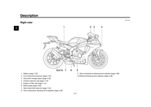 14
14 15
15 16
16 17
17 18
18 19
19 20
20 21
21 22
22 23
23 24
24 25
25 26
26 27
27 28
28 29
29 30
30 31
31 32
32 33
33 34
34 35
35 36
36 37
37 38
38 39
39 40
40 41
41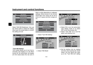 42
42 43
43 44
44 45
45 46
46 47
47 48
48 49
49 50
50 51
51 52
52 53
53 54
54 55
55 56
56 57
57 58
58 59
59 60
60 61
61 62
62 63
63 64
64 65
65 66
66 67
67 68
68 69
69 70
70 71
71 72
72 73
73 74
74 75
75 76
76 77
77 78
78 79
79 80
80 81
81 82
82 83
83 84
84 85
85 86
86 87
87 88
88 89
89 90
90 91
91 92
92 93
93 94
94 95
95 96
96 97
97 98
98 99
99 100
100 101
101 102
102 103
103 104
104 105
105 106
106 107
107 108
108 109
109 110
110 111
111 112
112 113
113 114
114 115
115 116
116 117
117 118
118 119
119 120
120 121
121 122
122 123
123