Page 17 of 124

Special features
3-2
1
234
5
6
7
8
9
10
11
12
cally adjusts accordin
g to the vehicle’s
lean angle. To maximize acceleration,
when the vehicle is upright a less
amount of traction control is applied.
When cornering, a greater amount of
traction control is applied.
TIP
The traction control system may
engage when the vehicle travels
over a bump.
You may notice slight changes in
engine and exhaust sounds when
the traction control or other YRC
systems engage.
When TCS is turned off, SCS,
LCS, and LIF are also turned offautomatically.
WARNING
EWA15432
The traction control system is not a
substitute for riding appropriately
for the conditions. Traction control
cannot prevent loss of traction due
to excessive speed when entering
turns, when accelerating hard at a
sharp lean angle, or while braking,
and cannot prevent front wheel slip-
ping. As with any motorcycle, ap-
proach surfaces that may be
slippery with caution and avoid es-pecially slippery surfaces.
When the key is turned to “ON”, the
traction control system automatically
turns on. The traction control system
can be turned on or off manually only
when the key is in the “ON” position and
the motorcycle is stopped.TIPTurn the traction control system off to
help free the rear wheel if the motorcy-
cle gets stuck in mud, sand, or othersoft surfaces.
NOTICE
ECA16801
Use only the specified tires. (See
page 7-19.) Using different sized
tires will prevent the traction control
system from controlling tire rotationaccurately.
SCS
The slide control system regulates en-
gine power output when a sideward
slide is detected in the rear wheel. It ad-
justs power output based on data from
the IMU. This system supports the TCS
to contribute to a smoother ride.
LCS
The launch control system helps the rid-
er achieve smooth and swift launches
from the starting grid. It keeps engine
speed from rising above 8,000 r/min
even when the throttle grip is fully
turned. The LCS regulates engine pow-
er output in conjunction with the TCS
and LIF systems for optimal traction and
reduced wheel lift.
TCS
BX4-9-E2.book 2 ページ 2018年9月6日 木曜日 午後4時39分
Page 18 of 124

Special features
3-3
1
23
4
5
6
7
8
9
10
11
12
NOTICE
ECA22950
Even when using LCS, the clutch le-
ver must be released gradually toavoid clutch damage.TIPLCS is intended for track use only.
QSS
The quick shift system allows for clutch
lever-less, electronically-assisted shift-
ing. When the sensor on the shift rod
detects the appropriate motion in the
shift pedal, engine power output is mo-
mentarily adjusted to allow for the gear
change to occur.
QSS does not operate when the clutch
lever is pulled, therefore normal shifting
can be done even when QSS is set to
on. Check the QS indicator for current
status and usability information. Upshifting conditions
Vehicle speed of at least 20 km/h
(12 mi/h)
Engine speed of at least 2200 r/min
Accelerating (open throttle)
Downshifting conditions
Vehicle speed of at least 20 km/h
(12 mi/h)
Engine speed of at least 2000 r/min
Engine speed sufficiently away
from red zone
Decelerating and throttle ful-
ly-closed
TIP
QS and QS can be individu-
ally set.
Shifting into or out of neutral mustbe done using the clutch lever.
LIF
The lift control system reduces the rate
at which the front wheel will continue to
rise during extreme acceleration, such
as during starts or out-of-corner exits.
When front-wheel lift is detected, en-
gine power is regulated to slow front-wheel lift while still providing good
acceleration.
QSS usability Indicator Situation
Upshifting OK Accelerating
Downshifting
OK Decelerating
QSS cannot be
used Stopped
QSS turned off Turned off
BX4-9-E2.book 3 ページ 2018年9月6日 木曜日 午後4時39分
Page 19 of 124
Special features
3-4
1
234
5
6
7
8
9
10
11
12
EAU85770
GlossaryABS - Anti-lock Brake System
ABS ECU - Anti-lock Brake System
Electronic Control Unit
ECU - Engine Control Unit
IMU - Inertial Measurement Unit
LCS - Launch Control System
LIF - Lift Control System
PWR - Power delivery mode
QS - Quick Shift
QSS - Quick Shift System
SC - Stability Control
SCS - Slide Control System
TCS - Traction Control System
UBS - Unified Brake System
YRC - Yamaha Ride Control
BX4-9-E2.book 4 ページ 2018年9月6日 木曜日 午後4時39分
Page 20 of 124
Special features
3-5
1
23
4
5
6
7
8
9
10
11
12
EAU66911
YRC functions visual guide1. Start
2. Acceleration
3. Braking
4. Apex
5. Exit 6. Straightaway
BX4-9-E2.book 5 ページ 2018年9月6日 木曜日 午後4時39分
Page 21 of 124

4-1
1
2
345
6
7
8
9
10
11
12
Instrument and control functions
EAU10979
Immobilizer systemThis vehicle is equipped with an immo-
bilizer system to help prevent theft by
re-registering codes in the standard
keys. This system consists of the fol-
lowing:
a code re-registering key
two standard keys
a transponder (in each key)
an immobilizer unit (on the vehicle)
an ECU (on the vehicle)
a system indicator light (page 4-7)
About the keys
The key with the red bow is used to reg-
ister codes in each standard key. Store the code re-registering key in a safe
place. When necessary, take the vehi-
cle along with all three keys to a
Yamaha dealer to have them re-regis-
tered.
Do not use the key with the red bow for
driving. It should only be used for
re-registering the standard keys. Al-
ways use a standard key for driving.
TIP
Keep the standard keys as well as
keys of other immobilizer systems
away from the code re-registering
key.
Keep other immobilizer system
keys away from the main switch as
they may cause signal interfer-ence.
NOTICE
ECA11823
DO NOT LOSE THE CODE RE-REG-
ISTERING KEY! CONTACT YOUR
DEALER IMMEDIATELY IF IT IS
LOST! If the code re-registering key
is lost, the existing standard keys
can still be used to start the vehicle.
However, registering a new stan-
dard key is impossible. If all keyshave been lost or damaged, the en-
tire immobilizer system must be re-
placed. Therefore, handle the keys
carefully.
Do not submerse in water.
Do not expose to high tempera-
tures.
Do not place near magnets.
Do not place near items that
transmit electrical signals.
Do not handle roughly.
Do not grind or alter.
Do not disassemble.
Do not put two keys of any im-
mobilizer system on the samekey ring.
1. Code re-registering key (red bow)
2. Standard keys (black bow)
BX4-9-E2.book 1 ページ 2018年9月6日 木曜日 午後4時39分
Page 22 of 124

Instrument and control functions
4-2
1
2
34
5
6
7
8
9
10
11
12
EAU10474
Main switch/steering lockThe main switch/steering lock controls
the ignition and lighting systems, and is
used to lock the steering. The various
positions are described below.TIPBe sure to use the standard key (black
bow) for regular use of the vehicle. To
minimize the risk of losing the code
re-registering key (red bow), keep it in a
safe place and only use it for codere-registering.
EAU85040
ON
All electrical circui ts are supplied with
power and the vehicle lights are turned on. The engine can be started. The key
cannot be removed.
TIP
To prevent battery discharge, do
not leave the key in the on position
without the engine running.
The headlight comes on automati-cally when the engine is started.
EAU10662
OFF
All electrical systems are off. The key
can be removed.
WARNING
EWA10062
Never turn the key to “OFF” or
“LOCK” while the vehicle is moving.
Otherwise the electrical systems will
be switched off, which may result inloss of control or an accident.
EAU1068B
LOCK
The steering is lock
ed and all electrical
systems are off. The key can be re-
moved. To lock the steering
1. Turn the handlebars all the way to
the left.
2. With the key in the “OFF” position, push the key in and turn it to
“LOCK”.
3. Remove the key.TIPIf the steering will not lock, try turningthe handlebars back to the right slightly.
P
ON
OFF
LOCK
1. Push.
2. Turn.12
BX4-9-E2.book 2 ページ 2018年9月6日 木曜日 午後4時39分
Page 23 of 124
Instrument and control functions
4-3
1
2
345
6
7
8
9
10
11
12
To unlock the steering
From the “LOCK” position, push the
key in and turn it to “OFF”.
EAU65680
(Parking)
The hazard lights can be turned on, but
all other electrical systems are off. The
key can be removed.
The steering must be locked before the
key can be turned to “ ”.NOTICE
ECA22330
Using the hazard lights for an ex-
tended length of time may cause thebattery to discharge.
EAU66055
Handlebar switchesLeft
Right
1. Push.
2. Turn.12
1. Pass/LAP switch “ /LAP”
2. Dimmer switch “ / ”
3. Hazard switch “ ”
4. Horn switch “ ”
5. Turn signal switch “ / ”
12543
1. Mode switch “MODE”
2. Up button
3. Center button
4. Down button
1. Stop/Run/Start switch “ / / ”
2. Wheel switch “ ”1
2
4 31
2
BX4-9-E2.book 3 ページ 2018年9月6日 木曜日 午後4時39分
Page 24 of 124

Instrument and control functions
4-4
1
2
34
5
6
7
8
9
10
11
12
EAU66091
Pass/LAP switch “ /LAP”
Press this switch to flash the headlights
and to mark the start of each lap when
using the lap timer.
EAU79872
Dimmer switch “ / ”
Set this switch to “ ” for the high
beam and to “ ” for the low beam.TIPWhen the switch is set to low beam,
only the left headlight comes on. When
the switch is set to high beam, bothheadlights come on.
EAU66040
Turn signal switch “ / ”
To signal a right-hand turn, push this
switch to “ ”. To signal a left-hand
turn, push this switch to “ ”. When re-
leased, the switch returns to the center
position. To cancel the turn signal
lights, push the switch in after it has re-
turned to the center position.
EAU66030
Horn switch “ ”
Press this switch to sound the horn.
EAU66060
Stop/Run/Start switch “ / / ”
To crank the engine with the starter, set
this switch to “ ”, and then push the
switch down towards “ ”. See page
6-1 for starting instructions prior to
starting the engine.
Set this switch to “ ” to stop the engine
in case of an emergency, such as when
the vehicle overturns or when the throt-
tle cable is stuck.
EAU66010
Hazard switch “ ”
With the key in the “ON” or “ ” posi-
tion, use this switch to turn on the haz-
ard lights (simultaneous flashing of all
turn signal lights).
The hazard lights are used in case of
an emergency or to warn other drivers
when your vehicle is stopped where it
might be a traffic hazard.NOTICE
ECA10062
Do not use the hazard lights for an
extended length of time with the en-
gine not running, otherwise the bat-tery may discharge.
EAU66111
Mode switch “MODE”
Use the mode switch to change YRC
modes or edit the PWR, TCS, and SCS
settings from the main screen. This
switch has three buttons.
Up button - push this button to change
the selected YRC setting upward.
Center button - push this button to
scroll left to right among the MODE,
PWR, TCS, and SCS items.
Down button - push this button to
change the selected YRC setting
downward.TIP
The center button is also used to
activate the launch control system.
When the LCS icon is grey, push
and hold the center button. The
LCS icon will flash and turn white
when the system has been activat-
ed.
The traction control system can
only be turned off from the main
screen. Select TCS with the center
button, then push and hold the up
button until TCS OFF is displayed.
To turn the traction control system
back on, use the down button.
BX4-9-E2.book 4 ページ 2018年9月6日 木曜日 午後4時39分
 1
1 2
2 3
3 4
4 5
5 6
6 7
7 8
8 9
9 10
10 11
11 12
12 13
13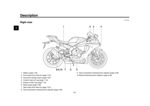 14
14 15
15 16
16 17
17 18
18 19
19 20
20 21
21 22
22 23
23 24
24 25
25 26
26 27
27 28
28 29
29 30
30 31
31 32
32 33
33 34
34 35
35 36
36 37
37 38
38 39
39 40
40 41
41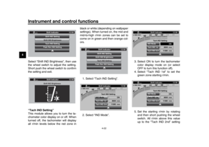 42
42 43
43 44
44 45
45 46
46 47
47 48
48 49
49 50
50 51
51 52
52 53
53 54
54 55
55 56
56 57
57 58
58 59
59 60
60 61
61 62
62 63
63 64
64 65
65 66
66 67
67 68
68 69
69 70
70 71
71 72
72 73
73 74
74 75
75 76
76 77
77 78
78 79
79 80
80 81
81 82
82 83
83 84
84 85
85 86
86 87
87 88
88 89
89 90
90 91
91 92
92 93
93 94
94 95
95 96
96 97
97 98
98 99
99 100
100 101
101 102
102 103
103 104
104 105
105 106
106 107
107 108
108 109
109 110
110 111
111 112
112 113
113 114
114 115
115 116
116 117
117 118
118 119
119 120
120 121
121 122
122 123
123


The hazard lights can b")