Page 33 of 124

Instrument and control functions
4-13
1
2
345
6
7
8
9
10
11
12
NOTICE
ECA10022
Do not continue to operate the en-gine if it is overheating.
Oil pressure warning “ ”
This icon appears when the engine oil
pressure is low. When the main switch
is first turned to ON, engine oil pressure
has yet to build, so this icon will come
on and stay on until the engine has
been started. NOTICE
ECA26410
Do not continue to operate the en-gine if the oil pressure is low.
Error mode warning “Err”
When an internal error occurs (e.g.,
communication with a system controller
has been cut off), the error mode warn-
ing will appear as follows.
“Err” and “ ” indicates an ECU error.
“Err” only indicates an HCU (hydraulic
control unit) error.TIPDepending on the nature of the error, the display may not function properly
and YRC settings may be impossible to
change. Additionally, ABS and UBS
may not function properly. Use extra
care when braking and have a Yamaha
dealer check the vehicle immediately.
EAU85790
MENU screenThe MENU screen contains the follow-
ing setting modules. Select a module to
make related setting changes. Al-
though some settings can be changed
or reset via the main screen, the MENU
screen offers access to all display and
control settings.
Module
Description
Switch the main screen
display between street and
track modes.
Adjust YRC settings.
View and reset lap times.
This function requires an
accessory part.
View and reset three
maintenance item
intervals.
YRC Setting
Lap TimeLogging
Maintenance
Unit
Display ModeMENU
km/h
GPS
12
:
00
Display ModeYRC SettingL ap TimeLoggingMaintenance
BX4-9-E2.book 13 ページ 2018年9月6日 木曜日 午後4時39分
Page 34 of 124

Instrument and control functions
4-14
1
2
34
5
6
7
8
9
10
11
12 MENU access and operation
The following wheel switch operations
are common operations for accessing,
selecting, and moving within the MENU
screen and its modules.
Long push - press and hold the wheel
switch for one second to access the
MENU screen or exit MENU entirely.
Select - rotate the wheel switch up or
down to highlight the desired module or
setting item and then short push the
wheel switch (briefly press the wheel
switch inward) to confirm the selection.
Triangle mark
- certain setting screens
have an upward pointing triangle mark
item. Select the triangle mark to exit
that screen and move back one screen
(or long push the wheel switch to exit MENU entirely).
TIPShould vehicle motion be detected, the
screen will automatically exit MENUand change to the main screen.
“Display Mode”
There are two main screen display
modes, STREET MODE and TRACK
MODE.
To set the main screen display mode1. Long push the wheel switch to en-
ter the MENU screen.
2. Select “Display Mode”. 3. Select STREET MODE or TRACK
MODE (or select the triangle mark
to exit).
4. Long push the wheel switch to exit the MENU screen or use the wheel
switch to select another module.
“YRC Setting”
This module allows you to customize
Set fuel consumption and
distance units.
Set background colors.
Turn the shift indicator on/
off and adjust tachometer
settings.
Set the multi-function
display window items.
Adjust screen brightness.
Adjust the clock.
Return all settings to
factory default settings.
Unit
WallpaperShift IndicatorDisplay SettingBrightnessCloc
k
All Reset
YRC Setting Lap TimeLogging
Maintenance
Unit
Display ModeMENU
km/h
GPS
12
:
00
YRC Setting
Lap TimeLogging
Maintenance
Unit
Display ModeMENU
km/h
GPS
12
:
00
km/h
12 :
00
TRACK MODE
STREET MODE
Display Mode
BX4-9-E2.book 14 ページ 2018年9月6日 木曜日 午後4時39分
Page 35 of 124
 of YRC items PWR,")
Instrument and control functions
4-15
1
2
345
6
7
8
9
10
11
12
the four YRC modes MODE-A,
MODE-B, MODE-C, MODE-D by ad-
justing the setting levels (or on/off sta-
tus as applicable) of YRC items PWR,
TCS, SCS, LCS, QSS, and LIF.
TIP
TCS has 9 setting levels.
Whenever there are more selec-
tions (setting levels or modes)
available than can be shown on
the screen at one time, a scroll bar
will appear to notify you that addi-
tional selections are available byscrolling.
PWR
Select PWR-1 for the most aggressive
throttle response, PWR-2 and PWR-3
for smoother throttle grip/engine re-
sponse, and use PWR-4 for rainy days
or whenever less engine power is desir-
able. TCS
This model uses a variable traction
control system. For each setting level,
the further the vehicle is leaned over,
the greater the amount of traction con-
trol (system intervention) is applied.
There are 9 setting levels available.
Setting level 1 applies the least amount
of overall system intervention, while
setting level 9 applies the greatest
amount of overall traction control.
TIP
TCS can only be turned on or off
via the main screen using the
mode switch.
When TCS has been turned off,
TCS, SCS, LCS, and LIF will be
set to OFF and cannot be adjust-
ed. When TCS is turned on again,
these related-traction control func-
tions will return to their previoussetting levels.
SCS
SCS can be set to OFF, 1, 2, and 3.
OFF turns the slide control system off,
setting level 1 provides the least
1. PWR 1
2. PWR 2
3. PWR 3
4. PWR 4
5. Throttle valve opening
6. Throttle grip operation
5 64
3 2
1
1. System intervention
2. Lean angle
1
TCS
2
1 5
4 3
2 6 9
8 7
BX4-9-E2.book 15 ページ 2018年9月6日 木曜日 午後4時39分
Page 36 of 124

Instrument and control functions
4-16
1
2
34
5
6
7
8
9
10
11
12 amount of system intervention, and set-
ting level 3 provides the greatest
amount of system intervention.
LCS
LCS can be set to 1, 2, or OFF. Setting
level 2 more strongly controls power
engine output, while setting level 1 ap-
plies less system intervention. OFF dis-
ables the LCS function from the
selected YRC mode (the LCS icon will
not appear and the launch control func-
tion cannot be activated).
When LCS has been set to level 1 or 2
for the selected YRC mode, the LCS in-
dicator on the main screen will appear
in a grey color to indicate that LCS is available. When the launch control sys-
tem has been activated (made ready
for use via the mode switch), the LCS
indicator will turn white.
TIPLCS works in conjunction with the LIF
system. LCS cannot be used if LIF isturned off.
QSS
The quick shift system is divided into
QS (upshift) and QS (downshift)
sections. QS and QS are not
linked and can be independently turned
on or off.
QS can be set to 1, 2, or OFF. Set-
ting level 1 is designed for maximum
acceleration, while setting level 2 is de-
signed to give smooth shifts at halfway
or less throttle openings. OFF turns the
respective upshift or downshift function
off, and the clutch lever must then be
used when shifting in that direction.TIP
Set QS to 1 for track or sporty
riding.
Set QS to 2 for touring or
around town-riding.
LIF
LIF can be set to 1, 2, 3, or OFF. Setting
level 3 most strongly reduces wheel lift,
and setting level 1 provides the least
amount of system intervention. OFF
turns LIF off and LCS will be disabled
for the selected YRC mode.
To customize a YRC mode or adjust a
YRC item1. From the MENU screen, select “YRC Setting”.
1. System intervention
2. Sideward slide
1 3
2
1
SCS
2
1. System intervention
2. Wheel lift
1 3
2
1
LIF
2
BX4-9-E2.book 16 ページ 2018年9月6日 木曜日 午後4時39分
Page 37 of 124

Instrument and control functions
4-17
1
2
345
6
7
8
9
10
11
12
2. The “YRC Setting” screen is dis-
played, and the YRC mode box
“YRC” is highlighted. Short push
the wheel switch to enter the box
and then select the YRC mode A,
B, C, D that you want to adjust. 3. Select the YRC item PWR, TCS,
SCS, LCS, QS , QS , or LIF
that you want to adjust.
TIP
When a YRC item is selected, the
current setting level is indicated by
a blue-framed square and the fac-
tory preset level is indicated in a
grey box.
Factory preset levels vary depend-ing on the selected YRC mode.
4. To customize other YRC modes or adjust individual YRC items, re-
peat from step 2. When finished, select the triangle mark on the far
left to return to the MENU screen.
“Lap Time”
This module allows you to view and de-
lete the lap time record. The fastest lap
and the average lap time stored in the
lap time record are displayed at the top
of the screen. Use the wheel switch to
scroll and see all lap times. The top
three fastest laps will be highlighted in
silver. Up to 40 laps can be stored in
memory. If more than 40 laps are re-
corded, the oldest laps (starting from
lap 1) will be overwritten.
This module has two options. “Display”
allows you to view the lap time record.
“Reset” allows you to delete the lap
time record data.
1. Triangle mark
2. YRC mode box
3. YRC item
YRC Setting Lap TimeLogging
Maintenance
Unit
Display ModeMENU
km/h
GPS
12
:
00
YRC
PWRTCS SCS LCS QS
LIF
12 :
00
YRC Setting
km/h
QS
A 1
5 2 1
111 1
ON
1
OFF
1
4 33 22
OFF
2OFF
3 2OFF
OFF
3
2
4
C B
D 1
13
2
1. YRC item
2. Current level setting
3. Factory preset level
4. YRC mode
YRC
PWRTCS SCS LCS QS
LIF
12
:
00
YRC Setting
QS
A 1
5 2 1
111 1
ON
1
OFF
1
4
km/h
33 22
OFF
2OFF
3 2OFF
OFF
3
2
4
C B
D 1
1
3 4
2
km/h
12
:
00
Reset
Display
Lap Time
BX4-9-E2.book 17 ページ 2018年9月6日 木曜日 午後4時39分
Page 38 of 124

Instrument and control functions
4-18
1
2
34
5
6
7
8
9
10
11
12 Use the wheel switch to select “Display”
and view the lap record.
To reset the lap time record data
1. When “Lap Time” is selected, both
“Display” and “Reset” are dis-
played. 2. Select “Reset”.
3. Select YES to delete all lap time
data. (Select NO to exit and return
to the previous screen without re-
setting the lap record.)
“Maintenance”
This module allows you to record dis-
tance traveled between engine oil
changes (use the OIL item), and for two other items of your choice (use INTER-
VAL 1 and INTERVAL 2).
To reset a maintenance item
1. From the MENU screen, select
“Maintenance”.
2. Select the item you want to reset.
3. Long push the wheel switch to re- set the item.
1. Fastest lap
2. Average lap time
3. Lap time record
LAP 1LAP 2LAP 3LAP 4 FA STEST / LAP 12
02:54.56
02:55.20
02:56.04
02:56.80 02:34.56
02:53.00
AVERAGE
Lap Time
km/h
GPGPS
12:
00
123
km/h
12 :
00
Reset
Display
Lap Time
km/h
12
:
00
Reset
Display
Lap TimeNO
Reset ?Lap Time
YES
km/h
GP GPS
12:
00
YRC Setting
Lap TimeLogging
Maintenance
Unit
Display ModeMENU
km/h
GPS
12
:
00
INTERVAL 2 OIL
INTERVAL 1
123456 km
123456 km
123456 km
Maintenance
km/h
GPS
12 :
00
BX4-9-E2.book 18 ページ 2018年9月6日 木曜日 午後4時39分
Page 39 of 124

Instrument and control functions
4-19
1
2
345
6
7
8
9
10
11
12
TIPMaintenance item names cannot bechanged.
“Unit”
This module allows you to switch the
display between kilometers and miles.
When using kilometers, the fuel con-
sumption units can be changed be-
tween km/L or L/100km. When using
miles, MPG will be available.
To set the distance or fuel consumptionunits1. From the MENU screen, select “Unit”. 2. “km or mile” and “km/L or L/100km”
are displayed.
3. Select the distance or consump- tion unit item you want to adjust. 4. Select the units you want to use.
5. Select the triangle symbol to exit.
“Wallpaper”
This module allows you to individually
set the STREET MODE and TRACK
MODE display background colors to
black or white for both day and night
settings. A photo sensor equipped in
INTERVAL 2 OIL
INTERVAL 1
0 km
123456 km
123456 km
Maintenance
km/h
GPS
12 :
00
YRC Setting
Lap TimeLogging
Maintenance
Unit
Display ModeMENU
km/h
GPS
12
:
00
km/L or L/100km km/Lkm or mile km
Unit
km/h
GP GPS
12:
00
km/L or L/100km km/Lkm or mile km
Unit
km/h
GPGPS
12:
00
km/L or L/100km km/Lkm or mile km
Unit
km/h
GP GPS
12:
00
BX4-9-E2.book 19 ページ 2018年9月6日 木曜日 午後4時39分
Page 40 of 124

Instrument and control functions
4-20
1
2
34
5
6
7
8
9
10
11
12 the instrument panel detects lighting
conditions and will automatically
change the display between its day and
night settings. The photo sensor also
controls a subtle automatic brightness
adjustment function within both day
and night modes to suit ambient light
conditions.
To set the wallpaper
1. From the MENU screen, select
“Wallpaper”. 2. Select the mode you want to adjust
(select DAY for daytime display
settings or NIGHT for nighttime
display settings).
3. Select the background color (se- lect BLACK for a black background
or WHITE for a white background).
4. Select the triangle symbol to exit.
5. To set another background color, repeat from step 2 or select the tri-
angle symbol to exit this module.
“Shift indicator”
The shift indicator module contains the
following modules.1. Photo sensor
1
GPGPS
TRACK MODE (day)
STREET MODE (night)
TRACK MODE (night) Wallpaper
STREET MODE (day)
km/h
12 :
00
WHITEBLACK
Wallpaper
STREET MODE (day)
km/h
GP GPS
12 :
00
Module Description
Set the shift indicator
pattern to “ON”, “Flash”,
or “OFF” and adjust at
what r/min the indicator
will come on and go off.
Adjust the brightness of
the shift indicator.
Set the tachometer color
display to “ON” or “OFF”
and adjust at what r/min
the tachometer will be
green and orange.
Set the tachometer peak
rev indicator to “ON” or
“OFF”.
GPGPS
TRACK MODE (day)
STREET MODE (night)
TRACK MODE (night) Wallpaper
STREET MODE (day)
km/h
12 :
00
Shift IND
SettingShift IND
BrightnessTach IND SettingPeak Rev IND Setting
BX4-9-E2.book 20 ページ 2018年9月6日 木曜日 午後4時39分
 1
1 2
2 3
3 4
4 5
5 6
6 7
7 8
8 9
9 10
10 11
11 12
12 13
13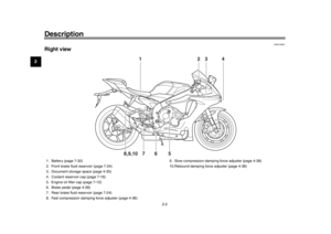 14
14 15
15 16
16 17
17 18
18 19
19 20
20 21
21 22
22 23
23 24
24 25
25 26
26 27
27 28
28 29
29 30
30 31
31 32
32 33
33 34
34 35
35 36
36 37
37 38
38 39
39 40
40 41
41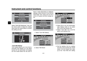 42
42 43
43 44
44 45
45 46
46 47
47 48
48 49
49 50
50 51
51 52
52 53
53 54
54 55
55 56
56 57
57 58
58 59
59 60
60 61
61 62
62 63
63 64
64 65
65 66
66 67
67 68
68 69
69 70
70 71
71 72
72 73
73 74
74 75
75 76
76 77
77 78
78 79
79 80
80 81
81 82
82 83
83 84
84 85
85 86
86 87
87 88
88 89
89 90
90 91
91 92
92 93
93 94
94 95
95 96
96 97
97 98
98 99
99 100
100 101
101 102
102 103
103 104
104 105
105 106
106 107
107 108
108 109
109 110
110 111
111 112
112 113
113 114
114 115
115 116
116 117
117 118
118 119
119 120
120 121
121 122
122 123
123