2019 MERCEDES-BENZ SPRINTER spare wheel
[x] Cancel search: spare wheelPage 242 of 354
SA
's Cus tomer Assis tance Center at 800-FOR-
MERC.
Fo r Canada, please contact MBC’s Cust omer
Assis tance Center at 1-800-387-0 100.
Cust omer requ ests for co vered information
should be submitted via the same channels.
Fo r accident clarification purposes, thefo llowing
measures can be take n up toan hour af terthe
emer gency call has been initia ted:
R The cur rent vehicle position can be de ter‐
mined
R Avo ice connection totheve hicle occupants
can be es tablished Flat tire
Note
s onflat tires &
WARNING Risk of an accident when driv‐
ing wi thaflat tire
A flat tire greatly impairs driving characteris‐
tics, as well as steering and braking. #
Do not drive with a flat tire. #
Remo vetheflat tire and ins tallthe
spare wheel or consult a qualified spe‐
cialist workshop. In
theeve nt of a flat tire you ha vethefo llowing
possibilities depending on your vehicle's equip‐
ment:
R Vehicles with Mercedes PRO connec t:in
th eeve nt of a flat tire, you can call Roadside
Assis tance via theRo adside Assis tance call
button in theov erhead cont rol panel
(/ page 171).
R Allvehicles: change the wheel
(/ page 251). Batte
ry Note
s onthe12 V battery &
WARNING Risk of an accident due to
wo rkcar ried out incor rectly on the bat‐
te ry
Wo rkcar ried out incor rectly on the battery
can, forex ample, lead toa short circuit. This
can lead tofunction restrictions in saf ety-re l‐
eva nt sy stems, forex ample the lighting sys‐
te m, ABS (anti-lock braking sy stem) or ESP ® (Elect
ronic Stability Prog ram). The operating
saf ety of your vehicle may be restricted.
Yo u could lose control of theve hicle in the
fo llowing situations:
R when braking
R intheeve nt of ab rupt steering maneuvers
and/or when theve hicle's speed is not
adap tedto thero ad conditions #
Intheeve nt of a sho rtcircuit or a simi‐
lar incident, contact a qualified special‐
ist workshop immediately. #
Do not continue driving. #
Always ha vewo rkon the battery car ried
out at a qualified specialist workshop. R
Further information on ABS (/ page137)
R Further information on ESP ®
(/ page 138)
Me rcedes-Benz recommends that you ha vethe
12 V battery replaced at a qualified specialist
wo rkshop, e.g. at an authorized Mercedes-Benz
Center.
Should youwa nttoreplace the battery yourself,
obse rveth efo llowing information:
R Alwaysre place a defective battery with a bat‐
te ry which fulfills theve hicle's specific
re qu irements.
R Use de tach able parts such as theve nt hose,
elbow fitting or term inal co ver from the bat‐
te ry to be replaced.
R Make sure that theve nt hose is al ways con‐
nected toits original opening on the battery
side.
Ins tallth eex isting or newly supplied stop
plugs.
Otherwise, gases or battery acid could
escape.
R Make sure that the de tach able parts are con‐
nec ted in the same way as before.
Fo r saf etyre asons, Mercedes-Benz recommends
th at you only use bat teries that ha vebeen tested
and appr ovedfo ryo ur vehicle byMercedes-Benz.
These batteries pr ovide inc reased impact pr otec‐
tion topreve ntvehicle occupants from suf fering
acid bu rns should the battery be damaged in an
accident. 218
Breakdown assis tance
Page 258 of 354

R
Use snow chains only when thero ad sur face
is comple tely sno w-covered. Re mo vethe
snow chains as soon as possible when you
come toaro ad that is not sn ow-co vered.
R Local regulations may restrict the use of
snow chains. Obse rveth e applicable regula‐
tions before ins talling snow chains.
R Activate all-wheel drive be fore driving off with
snow chains (/ page119).
R If sn ow ch ains are ins talled, the maximum
permissible speed is 30 mph (5 0 km/h).
R Vehicles with Parking Assis t:do not use
Pa rking Assist PARKTRONIC if sn ow chains
are ins talled.
% You can deactivate ESP ®
to pull away
( / page 138). This all ows the wheels to
spin, achieving an increased driving forc e. Ti
re pressure Note
s on tire pressure &
WARNING Risk of accident due toinsuf‐
fi cient or excessive tire pressure
Underinfla ted or overinfla ted tires pose the
fo llowing risks:
R The tires may bur st, especially as the load
and vehicle speed increase.
R The tires may wearexcessively and/or
une venly, which may greatly impair tire
traction.
R The driving characteristics, as well as
st eering and braking, may be greatly
impaired. #
Comply with there commended tire
pressure and check the tire pressure of
all tires including the spare wheel regu‐
larly:
R at least once a month
R when the load changes
R before embarking on a lon ger journey
R if operating conditions change, e.g. off-
ro ad driving #
Adjust the tire pressure as necessar y.Driving wi
thtire pressure that is too high or too
low can:
R Shor tenth e service life of the tires. R
Cause increased tire damage.
R Adversely af fect handling characteristics and
th us driving saf ety, e.g. due to hydroplaning. &
WARNING Risk of an accident due to
insuf ficient tire pressu re
Ti re s with pressure that is too low can over‐
heat and bur stas a result.
In addition, they also suf fer from excessive
and/or ir regular wear, which can significantly
impair the braking properties and the han‐
dling characteristics. #
Avoid excessively low tire pressures in
all the tires, including the spare wheel. Ti
re pressure which is too low can cause:
R Tire malfunctions as a result of overheating
R Impaired handling characteristics
R Irre gular wear
R Increased fuel consum ption &
WARNING Risk of accident from exces‐
sive tire pressure
Ti re s with excessively high pressure can bur st
because they are damaged more easily by
highw ayfill, pot holes etc.
In addition, they also suf fer from ir regular
we ar, which can significantly impair the brak‐
ing properties and the handling characteris‐
tics. #
Avoid excessively high tire pressures in
all the tires, including the spare wheel. Excessively high tire pressure can
result in:
R Increased braking dis tance
R Impaired handling characteristics
R Irre gular wear
R Impaired driving com fort
R Susceptibility todamage &
WARNING Risk of accident caused by
re peated drop in tire pressure
If th e tire pressure drops repeatedly, the
wheel, valve or tire may be damaged.
Insuf ficient tire pressu recan cause the tires
to bur st. #
Inspect the tire for signs of fore ign
objects. 234
Wheels and tires
Page 262 of 354

Re
ar axle tire pressures on vehicles with rear wheel drive and Super Single tires
Max. rear axle load 7055 lbs (3200 kg)Ti
re s/disc wheel Vehicle load Max.rear axle load
7055 lbs (3200 kg)
225/75R16C 121/120R (122L) Fully laden
690 kPa (6.9 bar/100 psi)3)
285/65R16C 131R Fully laden 460 kPa (4.6 bar/67 psi)Max.
rear axle load 7716 lbs (3500 kg) Ti
re s/disc wheel Vehicle load Max.rear axle load
77 16 lbs (3500 kg)
225/75R16C 121/120R (122L) Fully laden
690 kPa (6.9 bar/100 psi)3)
285/65R16C 131R Fully laden 520 kPa (5.2 bar/75 psi)3)
Va lid touse for a short time as a spare wheel
on there ar axle for a maximum dis tance of
62 miles (100 km) and a maximum speed of
34 mph (55 km/h).
Be sure toalso obse rveth efo llowing fur ther rela‐
te d subjects:
R Notes on tire pressure (/ page 234)
R Tire and Loading In form ation placard
(/ page 240)
R Maximum tire pressure (/ page 245) Ti
re pressure moni tor Fu
nction of tire pressure monitor on single
tires &
DANG ER Risk of accident due toincor‐
re ct tire pressure
Every tire, including the spare (if pr ovided),
should be checked when cold at least once a
month and inflated tothe pressure recom‐
mended bytheve hicle manufacturer (see Tire
and Loading In form ation placard on the B-pil‐
lar on the driver ’sside or the tire pressure
label on the inside of the fuel filler flap of your
ve hicle). If your vehicle has tires of a dif fere nt
size than the size indicated on theTire and
Loading In form ation placard or the tire pres‐
sure table, you need todeterm ine the proper
tire pressure forth ose tires.
As an added saf etyfe ature, your vehicle has
been equipped with a tire pressure monitor‐ ing sy
stem (TPMS) that illuminates a low tire
pressure indicator lamp when one or more of
yo ur tires are significantly unde rinfla ted.
Ac cording ly, if the low tire pressure indicator
lamp lights up, you should stop and check
yo ur tires as soon as possible, and inflate
th em tothe proper pressure. Driving on a sig‐
nificant lyunde rinfla ted tire causes the tire to
ove rheat and can lead totire failure. Underin‐
fl ation also inc reases fuel consum ption and
re duces tire tread life, and may af fect the
ve hicle's handling and braking ability. Please
no te that the TPMS is not a substitute for
proper tire maintenance, and it is the driver's
re sponsibility tomaintain cor rect tire pres‐
sure, even if underinflation has not reached
th e le velto trig ger illumination of the TPMS
low tire pressure indicator lamp.
Yo ur vehicle has also been equipped with a
TPMS malfunction indicator toindicate when
th e sy stem is not operating properly. The
TPMS malfunction indicator is combined with
th e low tire pressure indicator lamp. When
th e sy stem de tects a malfunction, the indica‐
to r lamp will flash for appro ximately a minute
and then remain continuously illumina ted.
This sequence will continue upon subsequent
ve hicle start-ups as long as the malfunction
ex ists.
When the malfunction indicator is illuminated,
th e sy stem may not be able todetect or sig‐
nal low tire pressu reas intended. TPMS mal‐
functions may occur for a variet y of reasons,
including the ins tallation of incompatible 238
Wheels and tires
Page 268 of 354
tire's ability
tocome toast andstill on a wet pa ve‐
ment under controlled conditions on a specified
U. S. go vernment test sur face made from asphalt
and concr ete.
Te mp erature grade &
WARNING Risk of accident from tire
ove rheating and tire failure
The temp erature grade forth is tire is es tab‐
lished for a tire that is properly inflated and
not overloaded. Excessive speed, underinfla‐
tion, or excessive loading, either separately or
in combination, can cause excessive heat
build-up and possible tire failure. #
Obser vethere commended tire pres‐
sures and regular lych eck the tire pres‐
sure of all tires including the spare
wheel. #
Adjust the tire pressure as necessar y.The
temp erature grades are A (highest grade), B
and C. These relate toa tire's resis tance toheat
and its ability torelease heat on a specified test
wheel in laboratory tests under contro lled condi‐
tions. Sus tained high temp eratures can cause the
material of the tire todegenerate and reduce tire
life. In addition, excessively high temp eratures
can lead tosudden tire failure. Grade C refers to
a per form ance which all passenger vehicle tires
must exhibit, according totheU. S. Depa rtment
of Transpor tation's requ irements. Information on DOT and TIN (Tire Identifica‐
tion Number) U.
S. tire regulations indicate that every tire man‐
ufacturer or retreader mu stimprint a TIN in or on
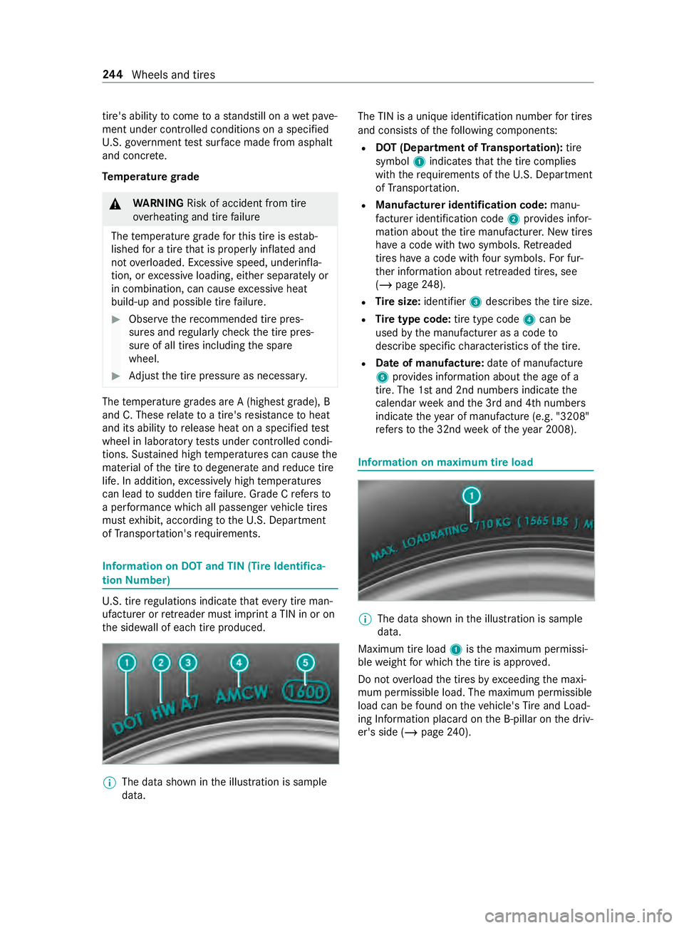
th e side wall of each tire produced. %
The data shown in
the illustration is sample
data. The TIN is a unique identification number
for tires
and consists of thefo llowing components:
R DOT (Department of Transportation): tire
symbol 1indicates that the tire complies
with therequ irements of theU. S. Depa rtment
of Transpor tation.
R Manufacturer identi fication code: manu‐
fa cturer identification code 2prov ides infor‐
mation about the tire manufacturer. New tires
ha ve a code with two symbols. Retreaded
tires ha vea code with four symbols. For fur‐
th er information about retreaded tires, see
(/ page 248).
R Tire size: identifier 3describes the tire size.
R Tire type code: tire type code 4can be
used bythe manufacturer as a code to
describe specific characteristics of the tire.
R Date of manu factu re:da te of manufacture
5 prov ides information about the age of a
tire. The 1st and 2nd numbers indicate the
calendar week and the 3rd and 4th numbers
indicate theye ar of manufacture (e.g. "3208"
re fers to the 32nd week of theye ar 2008). Information on maximum tire load
%
The data shown in
the illustration is sample
data.
Maximum tire load 1isthe maximum permissi‐
ble weight for which the tire is appr oved.
Do not overload the tires by exceeding the maxi‐
mum permissible load. The maximum permissible
load can be found on theve hicle's Tire and Load‐
ing In form ation placard on the B-pillar on the driv‐
er's side (/ page240). 244
Wheels and tires
Page 271 of 354
Ra
ting. You can find the Gross Axle Weight Rating
on the B-pillar on the driver's side.
Speed rating: the speed rating is pa rtof the tire
identification. It specifies the speed range for
which a tire is appr oved.
GV W (Gross Vehicle Weight): the Gross Vehicle
We ight includes thewe ight of theve hicle includ‐
ing fuel, tools, the spare wheel, accessories
ins talled, occupants, luggage and the trailer
dr aw bar nose weight if applicable. The Gross Vehi‐
cle Weight must ne verex ceed the Gross Vehicle
We ight Rating (GVWR) specified on the B-pillar on
th e driver's side.
GV WR (Gross Vehicle Weight Rating): the
GV WR is the maximum permitted gross weight of
th e fully laden vehicle (weight of theve hicle
including all accessories, occupants, fuel, lug‐
ga ge and the trailer dr awbar nose weight if appli‐
cable). The Gross Vehicle Weight Rating is speci‐
fi ed on theve hicle identification plate on the B-
pillar on the driver's side.
Maximum weight of the laden vehicle: the
maximum weight is the sum of theve hicle's curb
we ight, weight of the accessories, maximum load
and thewe ight of thefa ctory ins talled optional
equipment.
Kilopascal (kPa): metric unitfor tire pressu re.
6.9 kPa are the equivalent of 1 psi. Ano ther unit
fo r tire pressu reis bar. 100 kilopascals (kPa) are
th e equivalent of 1 bar.
Load index: in additiontothe load-bearing index,
th e load index may also be imprinted on the side‐
wa ll of the tire. This specifies the load-bearing
capacity more precisel y.
Curb weight: thewe ight of a vehicle with stand‐
ard equipment including the maximum capacity
of fuel, oil and coolant. It also includes the air-
conditioning sy stem and optional equipment if
th ese are ins talled on theve hicle, but does not
include passengers or luggage.
Maximum tire load: the maximum tire load is
th e maximum permissible weight in kilog rams or
lbs for which a tire is appro ved.
Maximum permissible tire pressure: maximum
permissible tire pressure for one tire.
Maximum load on one tire: maximum load on
one tire. This is calculated bydividing the maxi‐
mum axle load for one axle bytwo.
PSI (pounds per square in ch):standard unit of
measurement for tire pressu re. Aspect
ratio: relationship between tire height
and tire width in percent.
Ti re pressure: pressure inside the tire applying
an outward forc eto eve rysquare inch of the
tire's su rface. The tire pressure is specified in
pounds per square inch (psi), in kilopascal (kPa)
or in bar. The tire pressure should only be cor rec‐
te d when the tires are cold.
Ti re pressure on cold tires: the tires are cold
when theve hicle has been par ked with the tires
out of direct sunlight for at least thre e hours and
th eve hicle has been driven less than 1 mile
(1.6 km).
Ti re contact sur face: the part of the tire that
comes into con tact wi th thero ad.
Ti re bead: the purpose of the tire bead is to
ensure that the tire sits securely on the wheel
ri m. There are se veral wire cores in the tire bead
to preve ntthe tire from changing length on the
wheel rim.
Side wall:the part of the tire between the tread
and the tire bead.
Special equipment weight: the combined
we ight of those optional extras that we igh more
th an there placed standard parts and more than
5 lbs (2.3 kg). These op tionalextras, su chas
high-pe rformance brakes, le vel control sy stem, a
ro of luggage rack or a high-per form ance batter y,
are not included in the curb weight and the
we ight of the accessories.
TIN (Tire Identification Number): a unique iden‐
tification number which can be used bya tire
manufacturer toidentify tires, forex ample for a
product recall, and thus identify the pur chasers.
The TIN is made up of the manufacturer identifi‐
cation code, tire size, tire type code and the man‐
ufacturing date.
Load-bearing index: the load-bearing index (also
load index) is a code that con tains the maximum
load-bearing capacity of a tire.
Tr action: traction is there sult of friction between
th e tires and thero ad sur face.
We ar indicator: narrow bars (tread wear bars)
th at are distributed overth e tire tread. If the tire
tread is le vel with the bars, thewe ar limit of
1/ 16 in (1.6 mm) has been reached.
Distribution of vehicle occupants: distribution
of vehicle occupants over designated seat posi‐
tions in a vehicle. Wheels and tires
247
Page 274 of 354
degree of
wear. Ensure that the direction of rota‐
tion is maintained.
It is imperati vetoobser vethe instructions and
saf ety no tes on "Changing a wheel" when doing
so. Wheel size categories of wheels
The de
term ined vehicle speed is displa yed in the
instrument clus ter and is impor tant for control‐
ling the driving saf ety sy stems and driving sys‐
te ms. The display accuracy of the speedome ter
and the odome ter is legally prescribed. De term in‐
ing the speed is dependent on the tire size or the
ro lling circumference of the tires. The rim diame‐
te r is alw ays specified in inches.
Fo rth is reason, theve hicle contro l units can be
coded forth efo llowing thre e wheel size catego‐
ri es:
Wheel size category 1
R 195/75 R16C
R 205/75 R16C
R 225/65 R16C
R 235/65 R16C
R 235/60 R17C
Wheel size category 2 R 225/75 R16C
Wheel size category 3
R 225/75 R16C FA
R 285/65 R16C RA
% Mercedes-Benz
recommends that youstay
within a wheel size category when changing a
tire. In this wa y,yo uav oid recoding the con‐
trol units.
If yo uch ange the wheel size of your vehicle, for
ins tance when changing wheels for winter opera‐
tion, check it is assigned tothe cor rect wheel
size catego ry. If the wheel size category changes,
yo u must ha veyour vehicle's contro l unitsreco‐
ded at a qualified specialist workshop.
Otherwise, the display accuracy of the speedom‐
et er and the odome ter will be outside the legally
prescribed tolerance. It may also be lo wer,i.e.
th e cur rent road speed is then higher than the
speed shown on the speedome ter.If a deviation
is outside thera nge of tolerance, driving saf ety
sy stems and driving sy stems may be operation‐
ally impaired or may de tect a malfunction and
switch themselves off. Information on
the direction of the tires' rota‐
tion Ti
re s with a specified direction of rotation ha ve
additional benefits, e.g. if there is a risk of hydro‐
planing. You will on lyga in these benefits if the
cor rect direction of rotation is obser ved.
An ar rowonthe side wall of the tire indicates its
cor rect direction of rotation.
Yo u may also ins tall a spare wheel against the
direction of rotation. Obser vethe time restriction
on use as well as the speed limitation specified
on the spare wheel. Information on
storing wheels Obser
vethefo llowing when storing wheels:
R Wheels that ha vebeen remo ved should be
st ored in a cool, dry and, if possible, dark
place.
R Protect the tires from oil, grease and fuel. Overview of
the tire-chan getool kit Necessary tire-change
tools may include, for
ex ample:
R Jack
R Wheel wrench
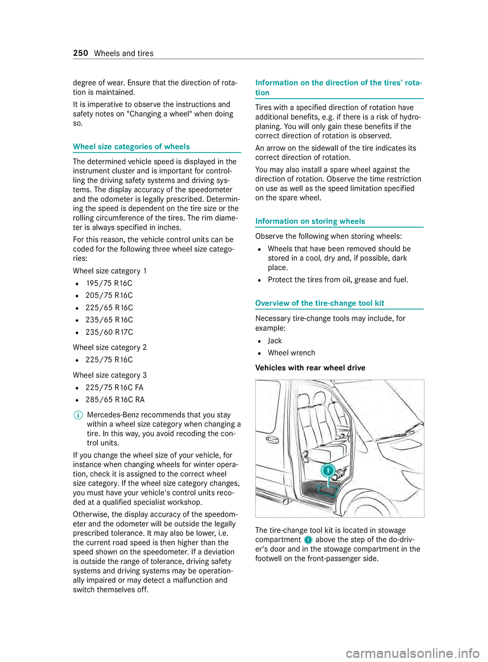
Ve hicles with rear wheel drive The tire-change
tool kit is located in stowage
compartment 1abo vethestep of the do-driv‐
er's door and in thestow age compartment in the
fo ot we ll on the front-passen ger side. 250
Wheels and tires
Page 278 of 354
&
WARNING Risk of inju ryfrom tightening
wheel bolts and nuts
If yo u tighten the wheel bolts or wheel nuts
when theve hicle is raised, the jack could tip. #
Only tighten wheel bolts or wheel nuts
when theve hicle is on the ground. #
Obser vethe information on thech oice of
tires (/ page248). #
For saf etyre asons, only use wheel bolts or
wheel nuts which ha vebeen appr ovedby
Mercedes-Benz and forth e wheel in question.
When you ins tallth esteel spare wheel, it is
essential you use short wheel bolts for a steel
wheel. Using other wheel bolts when ins talling
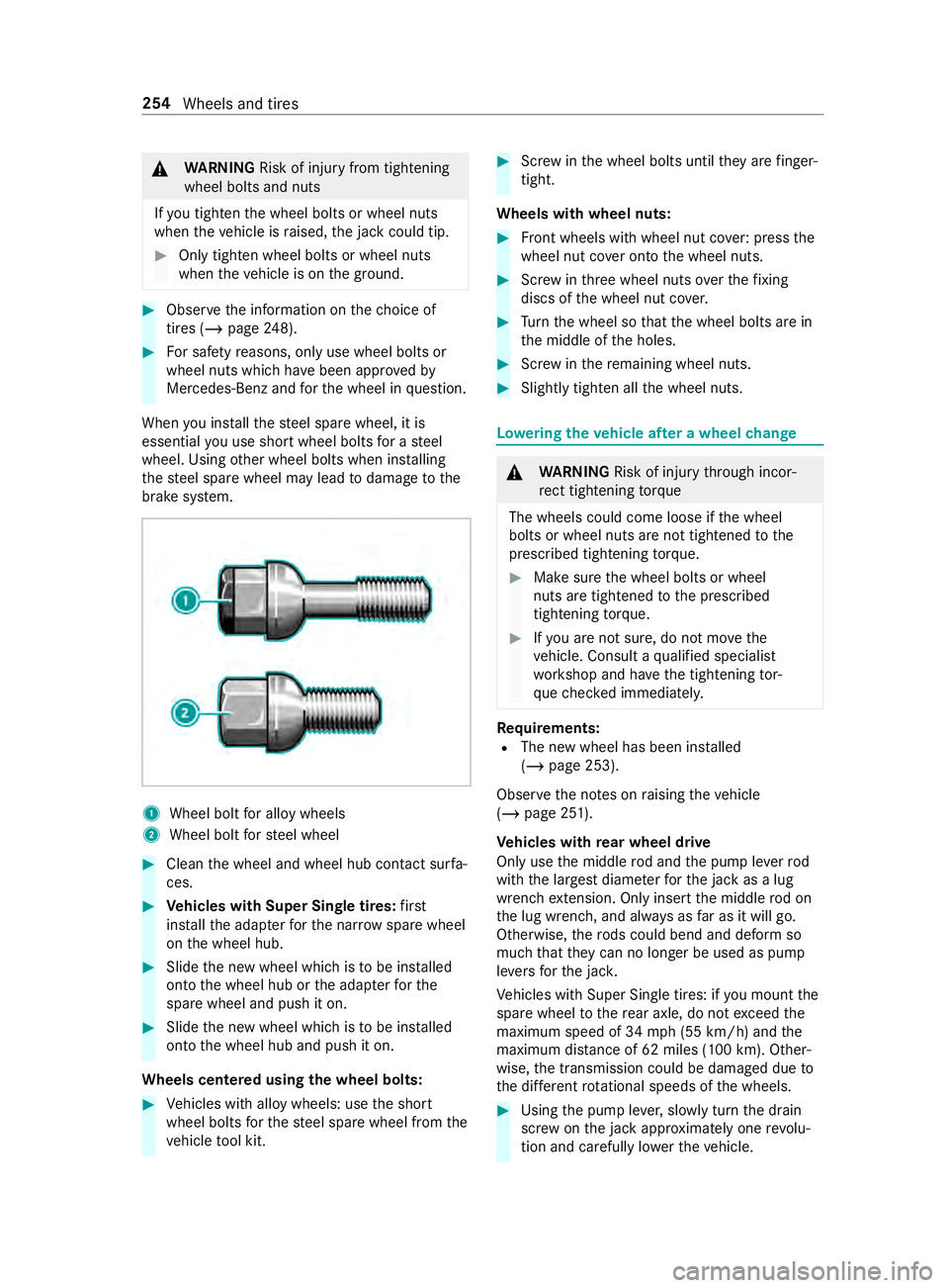
th esteel spare wheel may lead todamage tothe
brake sy stem. 1
Wheel bolt for alloy wheels
2 Wheel bolt forst eel wheel #
Clean the wheel and wheel hub contact sur fa‐
ces. #
Vehicles with Super Single tires: first
ins tallth e adap terfo rth e nar row spare wheel
on the wheel hub. #
Slide the new wheel which is tobe ins talled
onto the wheel hub or the adap terfo rthe
spare wheel and push it on. #
Slide the new wheel which is tobe ins talled
onto the wheel hub and push it on.
Wheels centered using the wheel bolts: #
Vehicles with alloy wheels: use the short
wheel bolts forth esteel spare wheel from the
ve hicle tool kit. #
Screw inthe wheel bolts until they are finger-
tight.
Wheels with wheel nuts: #
Front wheels with wheel nut co ver:press the
wheel nut co ver onto the wheel nuts. #
Screw inthre e wheel nuts overth efixing
discs of the wheel nut co ver. #
Turn the wheel so that the wheel bolts are in
th e middle of the holes. #
Screw inthere maining wheel nuts. #
Slightly tighten all the wheel nuts. Lo
weri ngtheve hicle af ter a wheel change &
WARNING Risk of inju rythro ugh incor‐
re ct tigh tening torque
The wheels could come loose if the wheel
bolts or wheel nuts are not tightened tothe
prescribed tightening torque. #
Makesure the wheel bolts or wheel
nuts are tightened tothe prescribed
tightening torque. #
Ifyo u are not sure, do not mo vethe
ve hicle. Consult a qualified specialist
wo rkshop and ha vethe tightening tor‐
qu ech ecked immediately. Re
quirements:
R The new wheel has been ins talled
(/ page 253).
Obser vethe no tes on raising theve hicle
(/ page 251).
Ve hicles with rear wheel drive
Only use the middle rod and the pump le verrod
with the largest diame terfo rth e jack as a lug
wrench extension. Only inse rtthe middle rod on
th e lug wrench, and alw ays as far as it will go.
Otherwise, thero ds could bend and deform so
much that they can no longer be used as pu mp
le ve rs forth e jac k.
Ve hicles with Super Single tires: if you mount the
spare wheel tothere ar axle, do not exceed the
maximum speed of 34 mph (55 km/h) and the
maximum dis tance of 62 miles (100 km). Other‐
wise, the transmission could be damaged due to
th e dif fere nt rotational speeds of the wheels. #
Using the pump le ver,slowly turn the drain
scr ew onthe jack appr oximately one revo lu‐
tion and carefully lo werth eve hicle. 254
Wheels and tires
Page 279 of 354

#
Place the jack toone side. #
Pull thero d with the smallest diame ter off the
pump le ver.
The shor tened pu mpleve r ser ves as a lug
wrench extension. #
Starting with the middle rod, slide the lug
wrench extension as far as it will go onto the
lug wrench. #
Tighten the wheel bolts or nuts evenly in the
sequence indicated (1 to6 ).
Specified tightening torque:
R Steel wheel bolts: 177 lb-ft (240 Nm)
R Wheel nuts: 133 lb-f t(180 Nm)
R Alloy wheel bolts: 133 lb-f t(180 Nm) #
Push the pis ton on thehy draulic jack in again
and close the pressure release scr ew. #
Vehicles with all-wheel drive: turnthe jack
spindle clockwise as far as it will go.
% Yo
u can now ins tallth e hub caps on steel
wheels with wheel bolts. The ins tallation pro‐
cedure depends on whe ther the hub cap acts
as a trim that co vers the whole wheel, or just
co vers the center. #
Wheel with hub cap: position the opening for
th e tire valve in the hub cap overth e tire
va lve. #
Push the edge of the hub cap onto the wheel
ri m with bo thhands until it engages into
place. Make sure the hub cap retaining
cat ches engage on thesteel wheel. #
Wheel with central hub cap: positionthe
re taining lugs of the cent ral hub cap overthe
wheel bolts. #
Hitthe middle of the hub cap toengage it on
th e wheel. #
Secure thefa ulty wheel in the spare wheel
brac ket. #
Vehicles with Super Single tires: transport
th e defective rear wheel in the load area. The
re ar wheel is too lar geforth e spare wheel
brac ket. #
Check the tire pressure of the newly ins talled
wheel and adjust it if necessar y. #
Retighten the wheel bolts or wheel nuts tothe
specified tightening torque af terth eve hicle
has been driven 31miles (50 km). #
When using a wheel or spare wheel with a
new or newly painted wheel rim, ha vethe
wheel bolts or nuts retightened af ter appro x‐
ima tely 620 miles (1,000 km) to3,10 0 miles
(5,000 km).
% Ve
hicles with the tire pressure monitor
sy stem: all ins talled wheels must be equip‐
ped with functioning sensors.
Make sure toobser vethefo llowing fur ther rela‐
te d subject:
R Notes on tire pressure (/ page 234) Spare wheel
Note
s onthe spa rewheel &
WARNING Risk of accident caused by
incor rect wheel and tire dimensions
Wheel and tire dimensions as well as the type
of tire may vary between the spare wheel and
th e wheel tobe replaced. When the spare
wheel is ins talled, driving characteristics may
be se verely af fected.
To prev ent hazardous situations: #
Adapt your driving style according lyand
drive carefull y. #
Never ins tall more than one spare wheel
th at dif fers from the wheel tobe
re placed. #
Only use the spare wheel that dif fers
from the wheel tobe replaced for a
short time. #
Do not switch off ESP ®
. #
Have the spare wheel of a dif fere nt size
re placed at the nearest qualified spe‐
cialist workshop. The wheel and tire Wheels and tires
255