2019 MERCEDES-BENZ GLE COUPE wheel
[x] Cancel search: wheelPage 257 of 697
wa
rning lamp appears in the multifunction
displa y.
Af terth e cooling phase, the sy stem is again
av ailable without restriction.
Setting the vehicle le vel &
WARNING Risk of accident because
ve hicle le vel is too high
If yo u drive at a higher vehicle le vel,th e driv‐
ing characteristics may be impaired due to
th e higher vehicle centre of gravity.
The vehicle can drift outwards, forex ample,
when steering or cornering. #
Alw aysch oose a vehicle le vel which is
suited tothe driving style and thero ad
sur face conditions. &
WARNING Risk of entrapment from vehi‐
cle lo wering
When lo wering theve hicle, other people
could become trapped if their limbs are
between theve hicle body and the tyres or
underneath theve hicle. #
Make sure no one is underneath the
ve hicle or in the immediate vicinity of
th e wheel ar ches when theve hicle is
being lo wered. &
WARNING Risk of becoming trapped
due totheve hicle lo wering
Ve hicles with AIRMATIC or le vel control:
when you unload luggage or lea vetheve hi‐
cle, theve hicle firs trises slightly and then
re turns tothe set le vel shortly af terw ards.
Yo u or an yone else in the vicinity of the
wheel ar ches or the underbody could thus
become trapped.
The vehicle can also be lo wered af ter being
loc ked. #
When leaving theve hicle, make sure
th at nobody is in the vicinity of the
wheel ar ches or the underbody. *
NO
TEDama gedue tovehicle lo wering Pa
rts of the body could be damaged when
th eve hicle is lo wered. #
Make sure that there are no obs tacles
su ch askerbs underneath or in the
immediate vicinity of the body when the
ve hicle is being lo wered. Re
quirements:
R The vehicle has been star ted.
R The vehicle is not moving fasterthan
65 km/h. 254
Driving and parking
Page 259 of 697
ro
ad sur face, vehicle load and the drive program
selected.
The ROAD SUR FACE SCAN function de tects
areas of une venness in thero ad before you drive
ove rth em bymeans of a multifunction camera.
This reduces chassis mo vements.
The damping is adju sted individually toeach
wheel and depends on thefo llowing factors:
R Driving style, e.g. sporty R
Road condition, e.g. bumps
R Drive program
E- AC TIVE BODY CONTROL is comprised of the
fo llowing functions and components:
R ROAD SUR FACE SCAN
R Cur veinclination function CURVE
R Recovery mode
R Individual wheel control R
Air suspension with auto matic level control
R Speed-dependent lo wering toreduce fuel
consum ption
R Manual le vel adjustment
R ADS PLUS (Adaptive Damping Sy stem with
const ant adjustment of damping characteris‐
tics)
R DYNA MIC SELECT switch and le vel button 256
Driving and parking
Page 262 of 697
Drive prog
ramS uspension settings and vehicle le vel
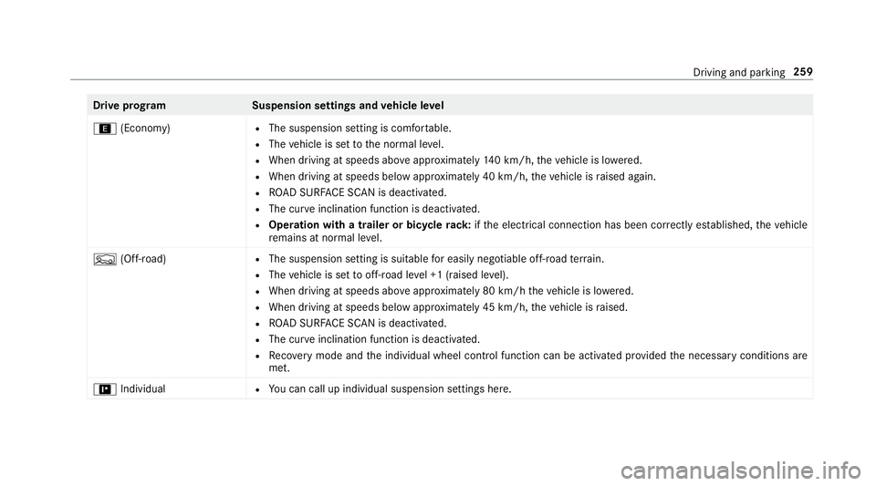
; (Economy) R
The suspension setting is comfor table.
R The vehicle is set tothe normal le vel.
R When driving at speeds abo veappr oximately 140 km/h, theve hicle is lo wered.
R When driving at speeds below appr oximately 40 km/h, theve hicle is raised again.
R ROAD SUR FACE SCAN is deactivated.
R The cur veinclination function is deactivated.
R Operation with a trailer or bicycle rack:ifth e electrical connection has been cor rectly es tablished, theve hicle
re mains at normal le vel.
F (Off-road) R
The suspension setting is suitable for easily negotiable off-road terrain.
R The vehicle is set tooff-road le vel +1 (raised le vel).
R When driving at speeds abo veappr oximately 80 km/h theve hicle is lo wered.
R When driving at speeds below appr oximately 45 km/h, theve hicle is raised.
R ROAD SUR FACE SCAN is deactivated.
R The cur veinclination function is deactivated.
R Recovery mode and the individual wheel control function can be activated pr ovided the necessary conditions are
met.
= Individual R
You can call up individual suspension settings here. Driving and parking
259
Page 264 of 697
R
If sections of thero ute ha veave ry small
ra dius of cur vature.
R During dynamic driving manoeuv res, e.g. if
yo u accelerate or brake theve hicle sharpl y.
Obser vethe no tes on cleaning the multifunction
camera (/ page 509).
Fu nction of reco very mode &
WARNING Risk of inju rydue totheve hi‐
cle moving up and down
When free driving mode is activated, the
ve hicle bounces up and down. Body parts
could become trapped if they are between
th eve hicle body and the tyres or underneath
th eve hicle. #
Make sure that nobody is under or in
th e immediate vicinity of theve hicle
when free driving mode is activated. *
NO
TERisk of dama gedue totheve hicle
moving up and down When free driving mode is activated,
the
ve hicle mo ves up and down. Vehicle parts
may be damaged if the underbody bottoms
out. #
Make sure that there is suf ficient
ground clearance when rocking free
mode is activated. Ro
cking free mode is a function of the suspen‐
sion which can assist the driver on loose sur fa‐
ces (e.g. sand, snow) when freeing a vehicle
which has become stuc k.
The vehicle body rock s in slo w,vertical motions
when reco very mode has been activated. This
te mp orarily puts the wheels under greater load,
which means they have inc reased traction and
th eve hicle is freed.
Yo u can activate free driving mode via Off- road
Assist (/ page 263). Fu
nction of individual wheel control &
WARNING Risk of becoming trapped
due totheve hicle lo wering
The vehicle can be lo wered when the individ‐
ual wheel control function has been activa‐
te d. Body parts could become trapped if they
are between theve hicle body and the tyres
or underneath theve hicle. #
Make sure that nobody is under the
ve hicle or in the immediate vicinity of
th e wheel ar ches when individual wheel
control is activated. *
NO
TERisk of dama gedue totheve hicle
moving up and down The
vehicle can be lo wered or raised on one
or more wheels when the individual wheel
control function has been activated. Vehicle
parts could be damaged due tocontact wi th
objects. #
Make sure that theve hicle has suf fi‐
cient room tomo vewhen the individual Driving and parking
261
Page 265 of 697
wheel control function has been activa‐
te
d. Individual wheel control is a function of
the sus‐
pension, which can be used toset theve hicle
le ve lfo r each wheel individually. This can help to
impr ove alignment of the body when driving off-
ro ad.
Yo u can activate individual wheel cont rol via Off-
ro ad Assist (/ page 263).
Setting theve hicle le vel &
WARNING Risk of accident because
ve hicle le vel is too high
If yo u drive at a higher vehicle le vel,th e driv‐
ing characteristics may be impaired due to
th e higher vehicle centre of gravity.
The vehicle can drift outwards, forex ample,
when steering or cornering. #
Alw aysch oose a vehicle le vel which is
suited tothe driving style and thero ad
sur face conditions. &
WARNING Risk of entrapment from vehi‐
cle lo wering
When lo wering theve hicle, other people
could become trapped if their limbs are
between theve hicle body and the tyres or
underneath theve hicle. #
Make sure no one is underneath the
ve hicle or in the immediate vicinity of
th e wheel ar ches when theve hicle is
being lo wered. &
WARNING Risk of becoming trapped
due totheve hicle lo wering
Ve hicles with AIRMATIC or le vel control:
when you unload luggage or lea vetheve hi‐
cle, theve hicle firs trises slightly and then
re turns tothe set le vel shortly af terw ards.
Yo u or an yone else in the vicinity of the
wheel ar ches or the underbody could thus
become trapped.
The vehicle can also be lo wered af ter being
loc ked. #
When leaving theve hicle, make sure
th at nobody is in the vicinity of the
wheel ar ches or the underbody. Re
quirements:
R The vehicle has been star ted.
R The vehicle is being driven no fasterthan
65 km/h. 262
Driving and parking
Page 267 of 697
R
theve hicle is outdoors
R the de tected la tera l inclination of theve hicle
must not exceed appr ox.15 °
R the sy stem is within its operating temp era‐
ture
R the on-board voltage is suf ficiently high
Multimedia sy stem:
4 © 5
Settings 5
Assistance
5 Offroad Assist
Re covery mode
Re covery mode assi ststh e driver when pulling
aw ay on rough terrain, such as sand or sn ow.#
Select Free driving mode. #
Select Start.
Re covery mode is activated. #
Select Stoptostop reco very mode.
Re covery mode is auto maticallydeactivated in
th efo llowing situations:
R you are actually tr avelling fasterthan
15 km/h
R afte r a running time of 30 seconds R
it is de tected that an object has hit the
underbody of theve hicle hard
R not all conditions are met
% Further information on reco very mode
(/ page 261).
Individual wheel control
Individual wheel control enables theve hicle le vel
to be set separately for each wheel. #
Select Individual wheel control. #
Set theve hicle le velfo rth e desired wheel.
% You can also use theto uch displ aytoset the
le ve lfo r two or more wheels at the same
time. #
Select Resettoset all wheels tothe default
setting.
Individual wheel control is automatically deacti‐
va ted in thefo llowing situations:
R you are tra velling fasterthan 15 km/h
R it is de tected that an object has hit the
underbody of theve hicle hard
R not all conditions are met %
Further information on individual wheel con‐
trol (/ page 261). Pa
rking Assist PARKTRONIC Fu
nction of Parking Assist PARKTRONIC
Pa rking Assist PARKTRONIC is an electronic
parking assi stance sy stem with ultrasound. It
monitors the area around your vehicle using six
sensors on the front bumper and six sensors on
th ere ar bumper. Parking Assist PARKTRONIC
sho wsyouth e dis tance between your vehicle
and a de tected obs tacle visually and audibly.
Pa rking Assist PARKTRONIC is on lyan aid. It is
not a substitute foryo ur attention tothe sur‐
ro undings. The responsibility for safe manoeu‐
vring and parking remains with you. Make sure
th at there are no persons, animals or objects in
th e manoeuvring area while manoeuvring and
parking in/exiting parking spaces.
In thest andard setting, an intermit tent wa rning
to ne sounds from a di stance of appr oximately
0.3 m toan obs tacle in front and appr oximately
1. 0 m toan obs tacle behind. A continuous warn‐ 264
Driving and parking
Page 274 of 697
R
The gradient is less than appr oximately 15%.
Ad justing the articulation angle of the trailer #
Select ¸.
The articulation angle can be changed on the
media display or on theto uchpad. #
Swipe left or right tochange the articulation
angle.
% The maximum articulation angle depends on
the length of the trailer. This is calculated by
th e sy stem bydriving theve hicle forw ards,
including cornering. Before the length of the
trailer has been calculated, the maximum
articulation angle is appr oximately 23°. The
longer the trailer is, the higher the maximum
articulation angle (max. appr oximately 60°). #
Set the desired articulation angle.
When the articulation angle entered has been
re ached, the dr awbar is loc kedby the sy stem so
th at the angle is maintained. Ac
tivating the stra ightening manoeuvre #
Select º.
The sy stem calculates the articulation angle
in such a wayth at the direction of the trailer
at the time of activation is maintained. There
is a short counter steering mo vement of the
trailer while theve hicle is reve rsed, which
th en guides it back tothe desired line. In this
wa y,theve hicle is aligned stra ight with the
trailer and, at the same time, the direction of
th e trailer is maintained. Re
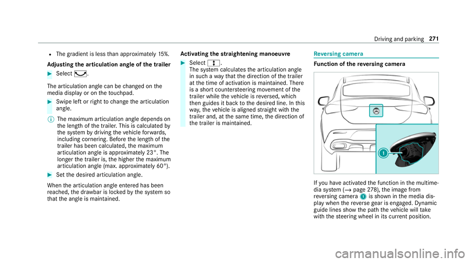
versing camera Fu
nction of there ve rsing camera If
yo u ha veactivated the function in the multime‐
dia sy stem (/ page278), the image from
re ve rsing camera 1is shown in the media dis‐
play when there ve rsege ar is engaged. Dynamic
guide lines show the path theve hicle will take
with thesteering wheel in its cur rent position. Driving and pa
rking 271
Page 275 of 697
This helps
youto orient yourself and to avoid
obs tacles when reve rsing.
The reve rsing camera is only an aid. It is not a
substitute foryo ur attention tothe sur roundings.
The responsibility for safe manoeuvring and
parking remains with you. Make sure that there
are no persons, animals or objects etc., in the
manoeuvring area while manoeuvring and park‐
ing.
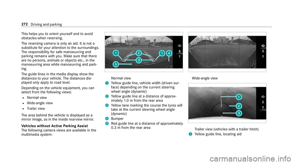
The guide lines in the media display show the
dis tances to yourvehicle. The dis tances dis‐
pl ay ed only apply toroad le vel.
Depending on theve hicle equipment, you can
select from thefo llowing vie ws:
R Normal view
R Wide-angle view
R Trailer view
The area behind theve hicle is displa yed as a
mir ror image, as in the inside rearview mir ror.
Ve hicles without Active Parking Assist
The following camera vie wsare available in the
multimedia sy stem: Normal view
1 Yellow guide line, vehicle width (driven sur‐
fa ce) depending on the cur rent steering
wheel angle (dynamic)
2 Yellow guide line at a dis tance of appr ox‐
imately 1.0 m from there ar area
3 Yellow lane marking the course the tyres will
ta ke atthe cur rent steering wheel angle
(dynamic)
4 Bumper
5 Red guide line at a dis tance of appr oximately
0.3 m from there ar area Wi
de-angle view Tr
ailer view (vehicles with a trailer hit ch)
1 Yellow guide line, locating aid 272
Driving and pa rking