2019 MERCEDES-BENZ GLE COUPE remove seats
[x] Cancel search: remove seatsPage 28 of 370

Protecting the environment
General notes
H
Environmental note
Daimler's declared policy is one of compre-
hensive environmental protection.
The objectives are for the natural resources
that form the basis of our existence on this
planet to be used sparingly and in a manner
that takes the requirements of both nature
and humanity into account.
You too can help to protect the environment
by operating your vehicle in an environmen-
tally responsible manner.
Fuel consumption and the rate of engine,
transmission, brake and tire wear are affected by these factors:
R operating conditions of your vehicle
R your personal driving style
You can influence both factors. You should
bear the following in mind:
Operating conditions:
R avoid short trips as these increase fuel con-
sumption.
R always make sure that the tire pressures
are correct.
R do not carry any unnecessary weight.
R remove roof racks once you no longer need
them.
R a regularly serviced vehicle will contribute
to environmental protection. You should
therefore adhere to the service intervals.
R always have service work carried out at a
qualified specialist workshop.
Personal driving style:
R do not depress the accelerator pedal when
starting the engine.
R do not warm up the engine when the vehicle
is stationary.
R drive carefully and maintain a safe distance
from the vehicle in front.
R avoid frequent, sudden acceleration and
braking. R
change gear in good time and use each gear
only up to 00C3of its maximum engine speed.
R switch off the engine in stationary traffic.
R keep an eye on the vehicle's fuel consump-
tion. Environmental concerns and recom-
mendations
Wherever the operating instructions require you to dispose of materials, first try to regenerate orre-use them. Observe the relevant environmen-
tal rules and regulations when disposing of
materials. In this way you will help to protect the environment. Genuine Mercedes-Benz parts
H
Environmental note
Daimler AG also supplies reconditioned major
assemblies and parts which are of the same
quality as new parts. They are covered by the same Limited Warranty entitlements as new
parts.
! Air bags and Emergency Tensioning Devi-
ces, as well as control units and sensors for
these restraint systems, may be installed in
the following areas of your vehicle:
R doors
R door pillars
R door sills
R seats
R cockpit
R instrument cluster
R center console
Do not install accessories such as audio sys-
tems in these areas. Do not carry out repairs or welding. You could impair the operating
efficiency of the restraint systems.
Have aftermarket accessories installed at a
qualified specialist workshop.
You could jeopardize the operating safety of
your vehicle if you use parts, tires and wheels as well as accessories relevant to safety which
have not been approved by Mercedes-Benz. This
could lead to malfunctions in safety-relevant 26
Genuine Mercedes-Benz partsIntroduction
Page 99 of 370
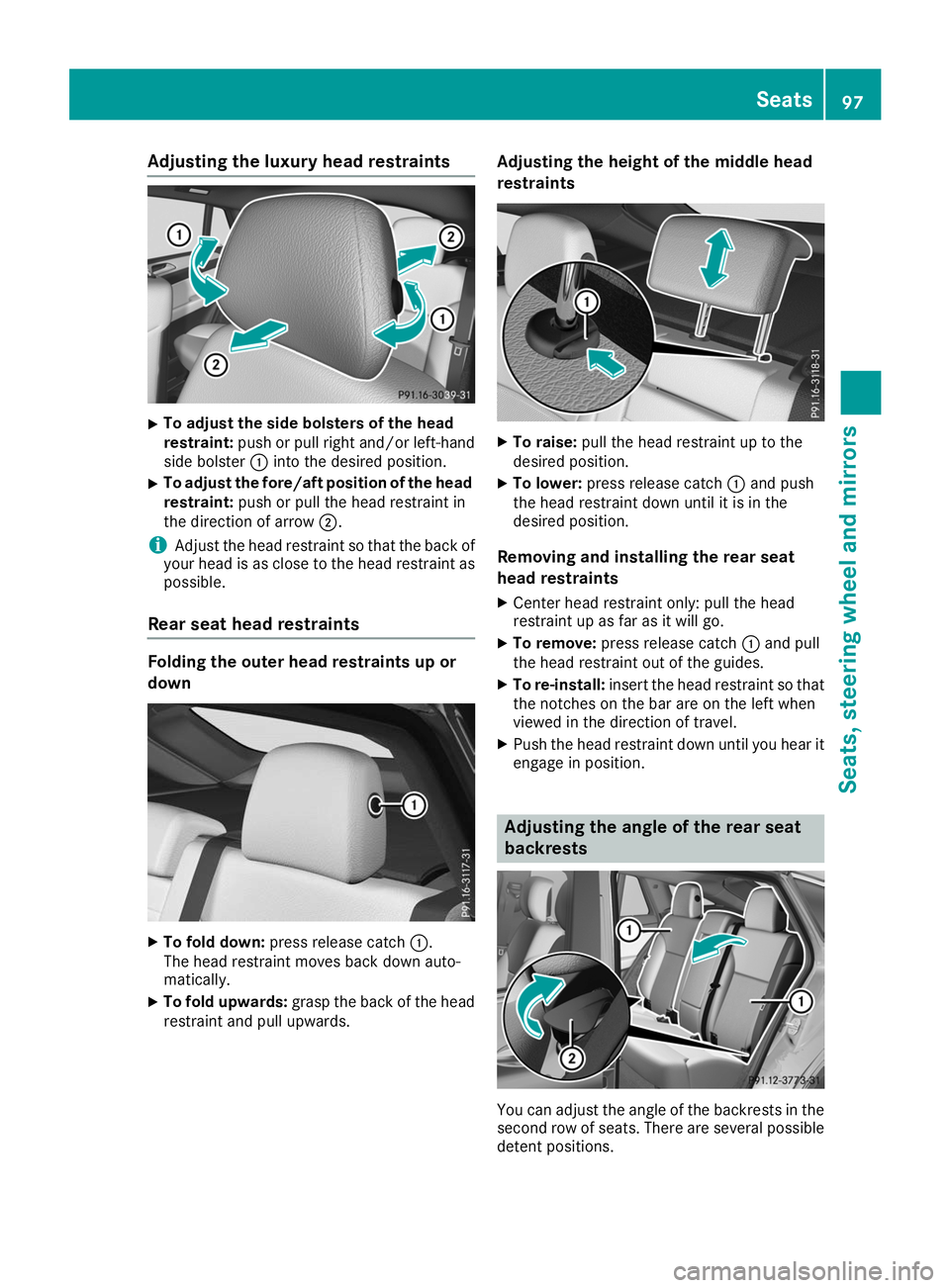
Adjusting the luxury head restraints
X
To adjust the side bolsters of the head
restraint:
push or pull right and/or left-hand
side bolster 0043into the desired position.
X To adjust the fore/aft position of the head
restraint: push or pull the head restraint in
the direction of arrow 0044.
i Adjust the head restraint so that the back of
your head is as close to the head restraint as possible.
Rear seat head restraints Folding the outer head restraints up or
down
X
To fold down: press release catch 0043.
The head restraint moves back down auto-
matically.
X To fold upwards: grasp the back of the head
restraint and pull upwards. Adjusting the height of the middle head
restraints
X
To raise: pull the head restraint up to the
desired position.
X To lower: press release catch 0043and push
the head restraint down until it is in the
desired position.
Removing and installing the rear seat
head restraints X Center head restraint only: pull the head
restraint up as far as it will go.
X To remove: press release catch 0043and pull
the head restraint out of the guides.
X To re-install: insert the head restraint so that
the notches on the bar are on the left when
viewed in the direction of travel.
X Push the head restraint down until you hear it
engage in position. Adjusting the angle of the rear seat
backrests
You can adjust the angle of the backrests in the
second row of seats. There are several possible
detent positions. Seats
97Seats, steering wheel and mirrors Z
Page 102 of 370
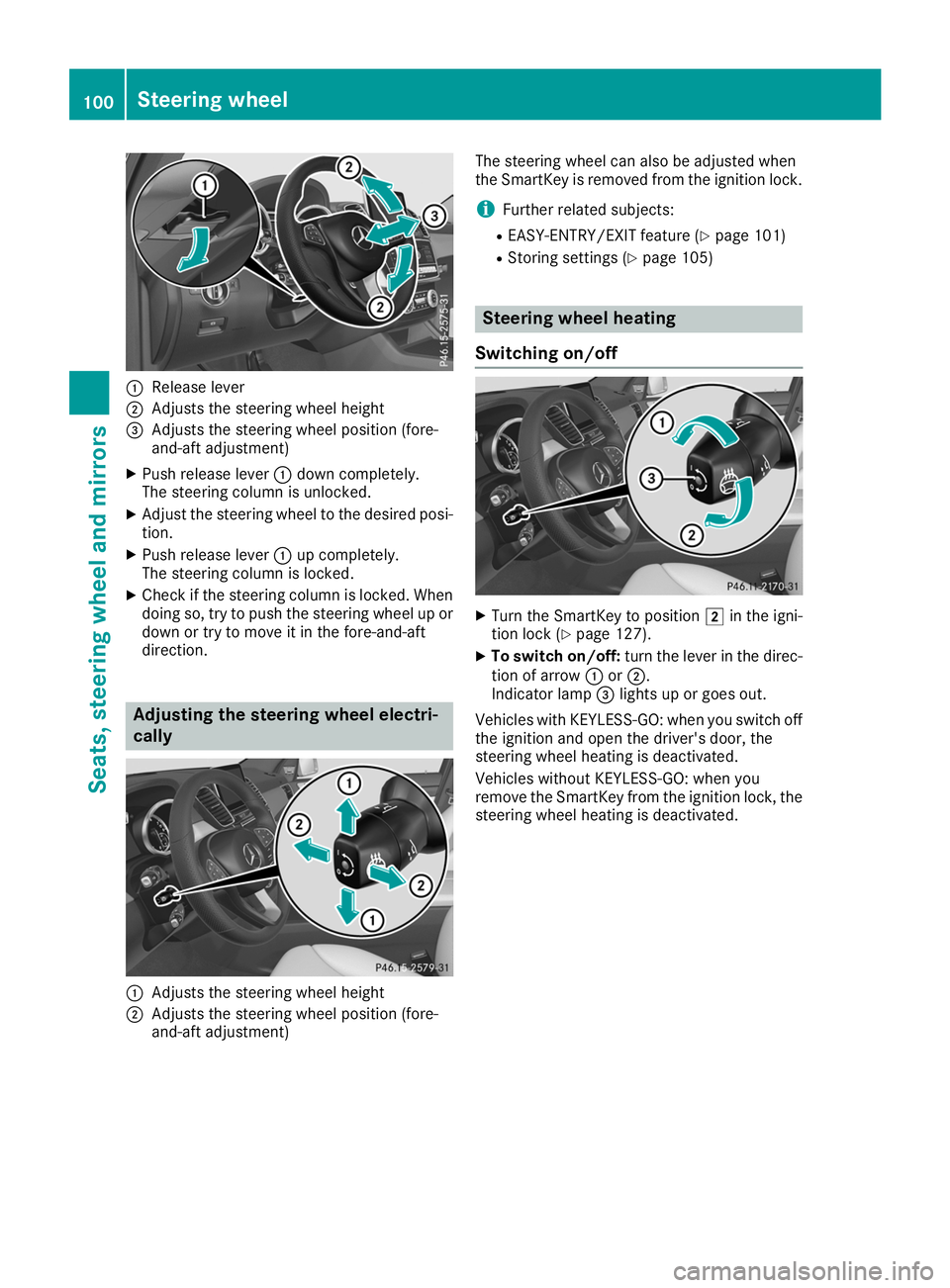
0043
Release lever
0044 Adjusts the steering wheel height
0087 Adjusts the steering wheel position (fore-
and-aft adjustment)
X Push release lever 0043down completely.
The steering column is unlocked.
X Adjust the steering wheel to the desired posi-
tion.
X Push release lever 0043up completely.
The steering column is locked.
X Check if the steering column is locked. When
doing so, try to push the steering wheel up or down or try to move it in the fore-and-aft
direction. Adjusting the steering wheel electri-
cally 0043
Adjusts the steering wheel height
0044 Adjusts the steering wheel position (fore-
and-aft adjustment) The steering wheel can also be adjusted when
the SmartKey is removed from the ignition lock.
i Further related subjects:
R EASY-ENTRY/EXIT feature (Y page 101)
R Storing settings (Y page 105) Steering wheel heating
Switching on/off X
Turn the SmartKey to position 0048in the igni-
tion lock (Y page 127).
X To switch on/off: turn the lever in the direc-
tion of arrow 0043or0044.
Indicator lamp 0087lights up or goes out.
Vehicles with KEYLESS-GO: when you switch off the ignition and open the driver's door, the
steering wheel heating is deactivated.
Vehicles without KEYLESS-GO: when you
remove the SmartKey from the ignition lock, the
steering wheel heating is deactivated. 100
Steering wheelSeats
, steering wheel and mirrors
Page 103 of 370
Problems with the steering wheel heating
Problem
Possible causes/consequences and
0050
0050Solutions The steering wheel heat-
ing has switched off pre-
maturely or cannot be
switched on. The on-board voltage is too low because too many electrical consum-
ers are switched on.
X Switch off electrical consumers that you do not need, such as the
rear window defroster or interior lighting. EASY-ENTRY/EXIT feature
Important safety notes G
WARNING
When the EASY-ENTRY/EXIT feature adjusts
the steering wheel, you and other vehicle
occupants – particularly children – could
become trapped. There is a risk of injury.
While the EASY-ENTRY/EXIT feature is mak-
ing adjustments, make sure that no one has
any body parts in the sweep of the steering
wheel.
Move the steering wheel adjustment lever if
there is a risk of entrapment by the steering
wheel. The adjustment process is stopped.
Press one of the memory function position but-
tons. This function is only available on vehicles
with memory function. G
WARNING
If children activate the EASY-ENTRY/EXIT fea- ture, they can become trapped, particularly
when unattended. There is a risk of injury.
When leaving the vehicle, always take the
SmartKey with you and lock the vehicle. Never leave children unsupervised in the vehicle. G
WARNING
If you drive off while the EASY-ENTRY/EXIT
feature is making adjustments, you could lose
control of the vehicle. There is a risk of an
accident.
Always wait until the adjustment process is
complete before driving off.
The EASY-ENTRY/EXIT feature makes getting in
and out of your vehicle easier. You can activate and deactivate the EASY-
ENTRY/EXIT feature in the on-board computer
(Y page 219).
Position of the steering wheel when the EASY-ENTRY/EXIT feature is active The steering wheel swings up when you:
R remove the SmartKey from the ignition lock.
R open the driver's door and KEYLESS-GO is in
position 0047.
R open the driver's door and the SmartKey is in
position 0092or0047 in the ignition lock.
i The steering wheel only moves up if it has
not already reached the upper stop.
Position of the steering wheel for driv-
ing The steering wheel is moved to the last selected
position when:
R the driver's door is closed
R you insert the SmartKey into the ignition lock
or
R you press the Start/Stop button once on vehi-
cles with KEYLESS-GO
When you close the driver's door with the igni-
tion switched on, the steering wheel is also
automatically moved to the previously set posi- tion.
The last position of the steering column is stored
when you:
R switch the ignition off
R save the setting with the memory function
(Y page 105).
Crash-responsive EASY-EXIT feature If the crash-responsive EASY-EXIT feature is trig-
gered in an accident, the steering column will
move upwards when the driver's door is opened. Steering wheel
101Seats, steering wheel and mirrors Z
Page 107 of 370
Memory function
Storing settings
G
WARNING
If you use the memory function on the driver's side while driving, you could lose control of
the vehicle as a result of the adjustments
being made. There is a risk of an accident.
Only use the memory function on the driver's
side when the vehicle is stationary. G
WARNING
When the memory function adjusts the seat or steering wheel, you and other vehicle occu-
pants – particularly children – could become
trapped. There is a risk of injury.
While the memory function is making adjust-
ments, make sure that no one has any body
parts in the sweep of the seat or steering
wheel. If somebody becomes trapped, imme-
diately release the memory function position
button. The adjustment process is stopped. G
WARNING
Children could become trapped if they acti-
vate the memory function, particularly when
unattended. There is a risk of injury.
When leaving the vehicle, always take the
SmartKey with you and lock the vehicle. Never leave children unsupervised in the vehicle.
The memory function can be used at any time,
e.g. even when the SmartKey isn't in the ignition
lock.
With the memory function, you can store up to
three different settings, e.g. for three different
people.
The following settings are stored as a single
memory preset:
R position of the seat, backrest and head
restraint
R driver's side: steering wheel position
R driver's side: position of the exterior mirrors
on the driver's and front-passenger sides X
Adjust the seat (Y page 95).
X On the driver's side, adjust the steering wheel
(Y page 100) and the exterior mirrors
(Y page 102).
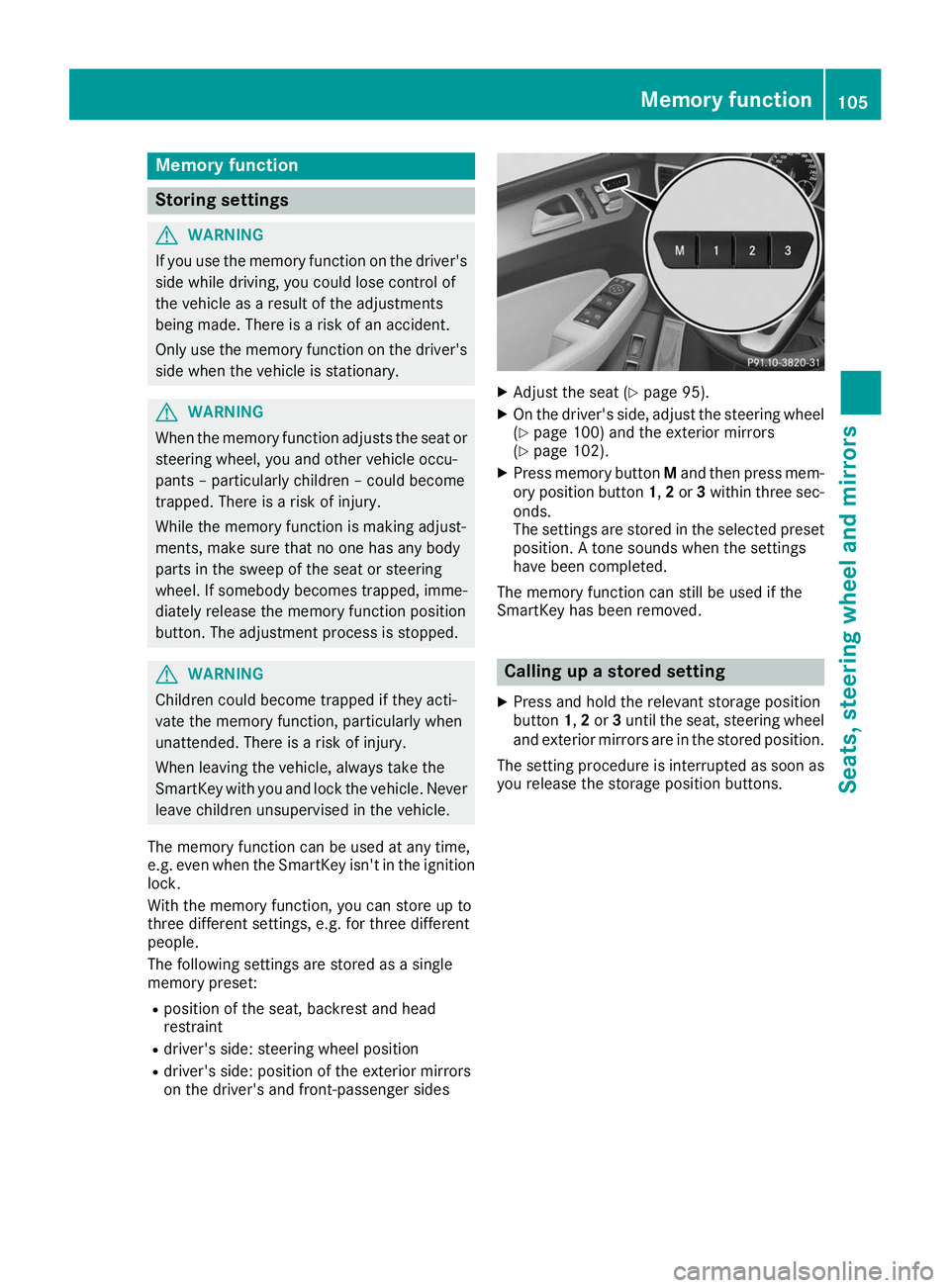
X Press memory button Mand then press mem-
ory position button 1,2or 3within three sec-
onds.
The settings are stored in the selected preset position. A tone sounds when the settings
have been completed.
The memory function can still be used if the
SmartKey has been removed. Calling up a stored setting
X Press and hold the relevant storage position
button 1,2or 3until the seat, steering wheel
and exterior mirrors are in the stored position.
The setting procedure is interrupted as soon as you release the storage position buttons. Memory function
105Seats, steering wheel and mirrors Z
Page 208 of 370
Important safety notes
G
WARNING
The bicycle rack can detach from the vehicle if
you
R exceed the permissible payload of the
trailer tow hitch
R use the bicycle rack incorrectly
R attach the bicycle rack to the ball coupling
beneath the ball head
There is a risk of an accident.
For your safety and that of other road users,
observe the following:
R Always observe the permissible payload of
the trailer tow hitch.
R Use the bicycle rack only to transport bicy-
cles.
R Always attach the bicycle rack correctly by
clamping onto the ball head and, if possible, to the guide pin on the ball coupling as well.
R To transport four bicycles, always use bicy-
cle racks with additional support on the ball
coupling's guide pin. R
Use only bicycle racks approved by
Mercedes-Benz.
R Always comply with the bicycle rack's oper-
ating manual.
! Using unsuitable bicycle racks or using
them incorrectly can cause damage to and
fractures in the trailer tow hitch.
Use only bicycle racks approved by
Mercedes-Benz.
Bicycle racks cause your vehicle's driving char-
acteristics to change. The vehicle:
R is heavier
R is restricted in its acceleration and gradient-
climbing capability
R has an increased braking distance
This could impair the handling characteristics.
Adapt your driving style accordingly. Maintain a safe distance and drive carefully.
When using bicycle racks, set the tire pressure
on the rear axle of the vehicle for the maximum
load. Further information on tire pressure can be
found on the tire pressure table (Y page 330).Loading instructions
The greater the distance between the load's center of gravity and the ball head, the higher the load exerted on the trailer tow hitch.
Therefore, observe the following notes:
R Attach heavy bicycles as close as possible to the vehicle.
R Always distribute the load on the bicycle rack as symmetrically as possible to the vehicle longi-
tudinal axis.
Before loading the bicycle rack, Mercedes-Benz advises you to remove all add-on parts from the
bicycles, e.g. bicycle baskets, child seats or batteries. This will allow you to improve the aerody-
namic resistance and the bicycle rack's center of gravity.
Always secure bicycles against slipping and check that they are firmly seated at regular intervals.
Do not use tarpaulins or other covers. This could impair the driving characteristics and rear visibility. The aerodynamic resistance would also rise, and so would the load exerted on the trailer tow hitchas a result. 206
Bicycle rackDriving and pa
rking
Page 284 of 370
blinded by incident light. There is a risk of an
accident.
Always keep the mirror cover folded down
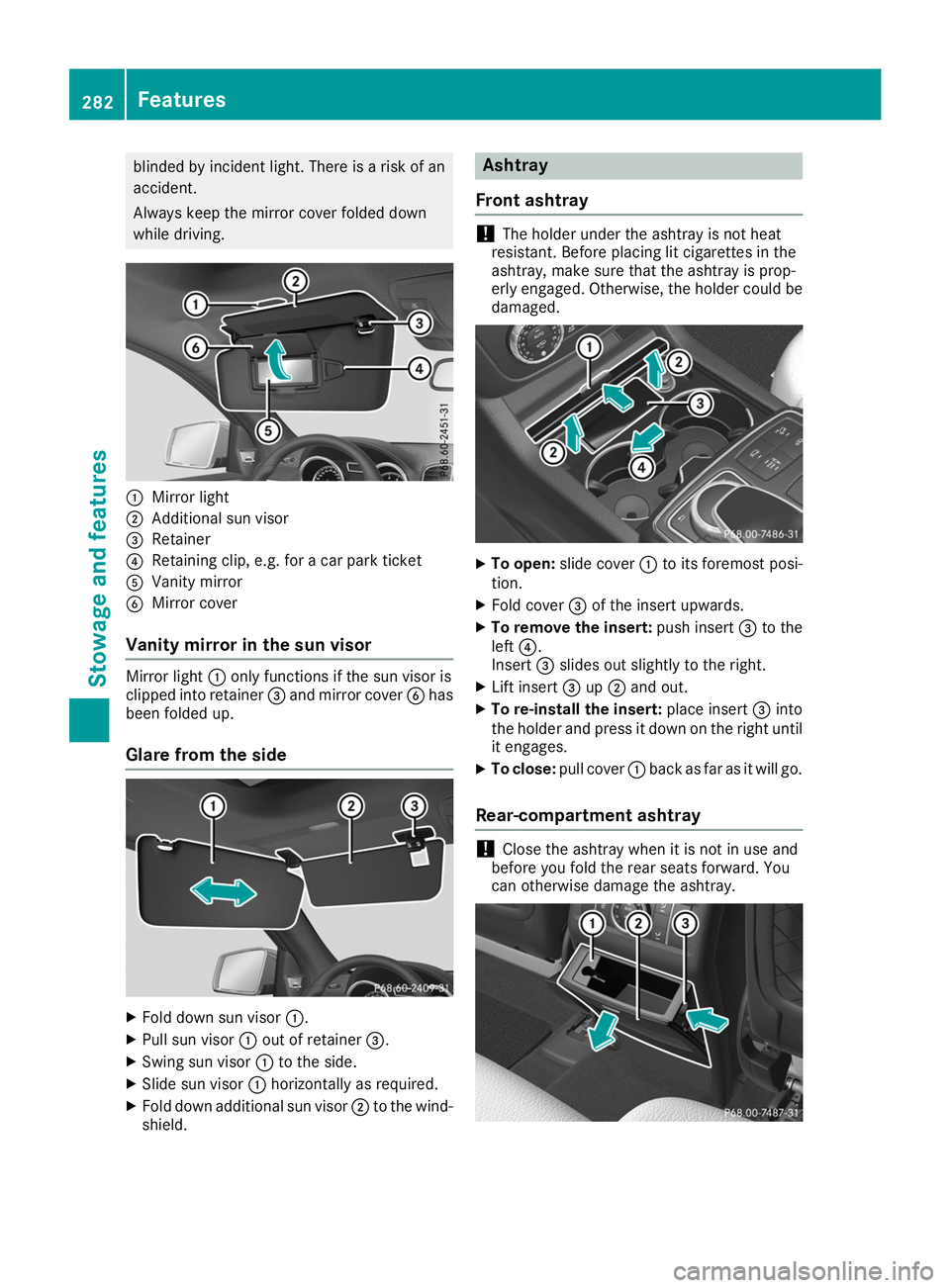
while driving. 0043
Mirror light
0044 Additional sun visor
0087 Retainer
0085 Retaining clip, e.g. for a car park ticket
0083 Vanity mirror
0084 Mirror cover
Vanity mirror in the sun visor Mirror light
0043only functions if the sun visor is
clipped into retainer 0087and mirror cover 0084has
been folded up.
Glare from the side X
Fold down sun visor 0043.
X Pull sun visor 0043out of retainer 0087.
X Swing sun visor 0043to the side.
X Slide sun visor 0043horizontally as required.
X Fold down additional sun visor 0044to the wind-
shield. Ashtray
Front ashtray !
The holder under the ashtray is not heat
resistant. Before placing lit cigarettes in the
ashtray, make sure that the ashtray is prop-
erly engaged. Otherwise, the holder could be
damaged. X
To open: slide cover 0043to its foremost posi-
tion.
X Fold cover 0087of the insert upwards.
X To remove the insert: push insert0087to the
left 0085.
Insert 0087slides out slightly to the right.
X Lift insert 0087up0044 and out.
X To re-install the insert: place insert0087into
the holder and press it down on the right until
it engages.
X To close: pull cover 0043back as far as it will go.
Rear-compartment ashtray !
Close the ashtray when it is not in use and
before you fold the rear seats forward. You
can otherwise damage the ashtray. 282
FeaturesStowage and features
Page 297 of 370
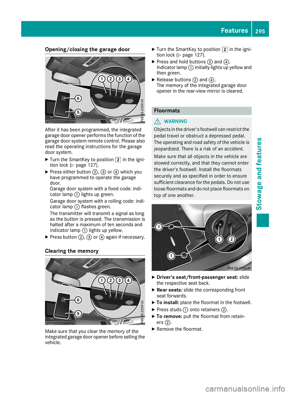
Opening/closing the garage door
After it has been programmed, the integrated
garage door opener performs the function of the
garage door system remote control. Please also
read the operating instructions for the garage
door system.
X Turn the SmartKey to position 0048in the igni-
tion lock (Y page 127).
X Press either button 0044,0087or0085 which you
have programmed to operate the garage
door.
Garage door system with a fixed code: indi-
cator lamp 0043lights up green.
Garage door system with a rolling code: indi-
cator lamp 0043flashes green.
The transmitter will transmit a signal as long
as the button is pressed. The transmission is
halted after a maximum of ten seconds and
indicator lamp 0043lights up yellow.
X Press button 0044,0087or0085 again if necessary.
Clearing the memory Make sure that you clear the memory of the
integrated garage door opener before selling the vehicle. X
Turn the SmartKey to position 0048in the igni-
tion lock (Y page 127).
X Press and hold buttons 0044and 0085.
Indicator lamp 0043initially lights up yellow and
then green.
X Release buttons 0044and 0085.
The memory of the integrated garage door
opener in the rear-view mirror is cleared. Floormats
G
WARNING
Objects in the driver's footwell can restrict the pedal travel or obstruct a depressed pedal.
The operating and road safety of the vehicle is
jeopardized. There is a risk of an accident.
Make sure that all objects in the vehicle are
stowed correctly, and that they cannot enter
the driver's footwell. Install the floormats
securely and as specified in order to ensure
sufficient clearance for the pedals. Do not use loose floormats and do not place floormats on
top of one another. X
Driver's seat/front-passenger seat: slide
the respective seat back.
X Rear seats: slide the corresponding front
seat forwards.
X To install: place the floormat in the footwell.
X Press studs 0043onto retainers 0044.
X To remove: pull the floormat from retain-
ers 0044.
X Remove the floormat. Features
295Stowage and features Z