2019 MERCEDES-BENZ GLE COUPE technical data
[x] Cancel search: technical dataPage 5 of 370
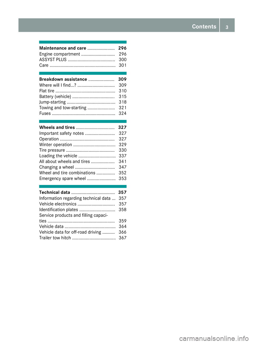
Maintenance and care
......................296
Engine compartment ........................... 296
ASSYST PLUS ...................................... 300
Care ..................................................... 301 Breakdown assistance
.....................309
Where will I find...? .............................. 309
Flat tire ................................................ 310
Battery (vehicle) .................................. 315
Jump-starting ....................................... 318
Towing and tow-starting ...................... 321
Fuses .................................................. .324 Wheels and tires
............................... 327
Important safety notes ........................ 327
Operation ............................................ 327
Winter operation .................................. 329
Tire pressure ....................................... 330
Loading the vehicle .............................. 337
All about wheels and tires ................... 341
Changing a wheel ................................ 347
Wheel and tire combinations .............. .352
Emergency spare wheel ....................... 353 Technical data
................................... 357
Information regarding technical data ... 357
Vehicle electronics .............................. 357
Identification plates ............................ .358
Service products and filling capaci-
ties ...................................................... 359
Vehicle data ......................................... 364
Vehicle data for off-road driving .......... 366
Trailer tow hitch ................................... 367 Contents
3
Page 10 of 370

Setting the climate mode (AIR
FLOW) ............................................ 120
Setting the temperature ................ 120
Switching air-recirculation mode
on/of f............................................ 123
Switching on/of f........................... 119
Switching residual heat on/off ...... 123
Switching the rear window
defroster on/of f............................ 122
Switching the ZONE function
on/of f............................................ 121
Coat hooks ......................................... 278
Cockpit
Overview .......................................... 35
see Instrument cluster
Collapsible spare wheel
Inflating ......................................... 356
see Emergency spare wheel
COMAND display
Cleaning ......................................... 307
Combination switch .......................... 107
Connecting a USB device
see also Digital Operator's Man-
ual .................................................. 264
Consumption statistics (on-board
computer) .......................................... 211
Controller ........................................... 265
Convenience closing feature .............. 87
Convenience opening feature ............ 87
Coolant (engine)
Checking the level ......................... 299
Display message ............................ 236
Filling capacity ............................... 363
Important safety notes .................. 362
Temperature (on-board computer, Mercedes-AMG vehicles) ............... 220
Temperature gaug e........................ 209
Warning lamp ................................. 260
Cooling
see Climate control
Copyright ............................................. 34
Cornering light function
Display message ............................ 235
Crash-responsive emergency light-
ing ....................................................... 110
Crosswind Assist ................................. 69
Crosswind driving assistance ............ 69Cruise control
Activating ....................................... 157
Activation conditions ..................... 156
Cruise control lever ....................... 156
Deactivating ................................... 157
Display message ............................ 244
Driving system ............................... 156
Function/note s............................. 156
Important safety notes .................. 156
Storing and maintaining current
speed ............................................. 157
Cup holder
Center console .............................. 281
Important safety notes .................. 280
Rear compartment ......................... 281
Temperature controlled ................. 281
Customer Assistance Center
(CAC) ..................................................... 31
Customer Relations Department ....... 31 D
Data see Technical data
Data carrier
Selecting ........................................ 214
Daytime running lamps
Display message ............................ 235
Function/note s............................. 106
Switching on/off (on-board com-
puter) ............................................. 218
Declarations of conformity ................. 29
Decorative film
Cleaning instructions ..................... 303
Diagnostics connection ...................... 30
Digital Operator's Manual
Help ................................................. 25
Introduction ..................................... 25
Digital speedometer ......................... 212
DIRECT SELECT lever
Automatic transmission ................. 135
Display messages
ASSYST PLU S................................ 300
Calling up (on-board computer) ..... 223
Driving systems ............................. 239
Engine ............................................ 236
General notes ................................ 222
Hiding (on-board computer) ........... 223 8
Index
Page 22 of 370
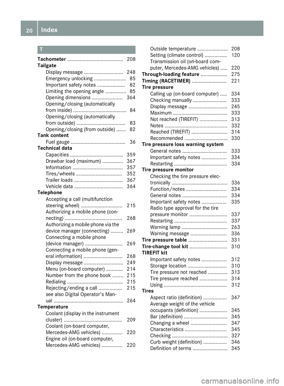
T
Tachometer ........................................ 208
Tailgate
Display message ............................ 248
Emergency unlocking ....................... 85
Important safety notes .................... 82
Limiting the opening angle ............... 85
Opening dimensions ...................... 364
Opening/closing (automatically
from inside) ...................................... 84
Opening/closing (automatically
from outside) ................................... 83
Opening/closing (from outside) ....... 82
Tank content
Fuel gauge ....................................... 36
Technical data
Capacities ...................................... 359
Drawbar load (maximum) ............... 367
Information .................................... 357
Tires/wheels ................................. 352
Trailer load s................................... 367
Vehicle data ................................... 364
Telephone
Accepting a call (multifunction
steering wheel) .............................. 215
Authorizing a mobile phone (con-
necting) ......................................... 268
Authorizing a mobile phone via the device manager (connecting )......... 269
Connecting a mobile phone
(device manager) ........................... 269
Connecting a mobile phone (gen-
eral information) ............................ 268
Display message ............................ 249
Menu (on-board computer) ............ 214
Number from the phone book ........ 215
Redialing ........................................ 215
Rejecting/ending a call ................. 215
see also Digital Operator's Man-
ual .................................................. 264
Temperature
Coolant (display in the instrumentcluster) .......................................... 209
Coolant (on-board computer,
Mercedes-AMG vehicles) ............... 220
Engine oil (on-board computer,
Mercedes-AMG vehicles) ............... 220 Outside temperature ...................... 208
Setting (climate control )................ 120
Transmission oil (on-board com-
puter, Mercedes-AMG vehicles) ..... 220
Through-loading feature ................... 275
Timing (RACETIMER) ......................... 221
Tire pressure
Calling up (on-board computer) ..... 334
Checking manually ........................ 333
Display message ............................ 245
Maximum ....................................... 333
Not reached (TIREFIT) .................... 313
Notes ............................................. 332
Reached (TIREFIT) .......................... 314
Recommended ............................... 330
Tire pressure loss warning system
General notes ................................ 333
Important safety notes .................. 334
Restarting ...................................... 334
Tire pressure monitor
Checking the tire pressure elec-
tronically ........................................ 336
Function/note s............................. 334
General notes ................................ 334
Important safety notes .................. 335
Radio type approval for the tire
pressure monitor ........................... 337
Restarting ...................................... 337
Warning lamp ................................. 263
Warning message .......................... 336
Tire pressure table ............................ 331
Tire-change tool kit ........................... 310
TIREFIT kit
Important safety notes .................. 312
Storage location ............................ 310
Tire pressure not reached .............. 313
Tire pressure reached .................... 314
Using ............................................. 312
Tires
Aspect ratio (definition) ................. 347
Average weight of the vehicle
occupants (definition) .................... 345
Bar (definition) ............................... 345
Changing a whee l.......................... 347
Characteristics .............................. 345
Checking ........................................ 327
Curb weight (definition) ................. 346
Definition of terms ......................... 345 20
Index
Page 32 of 370
These devices may not cause harmful interfer-
ence, and 2) These devices must accept any
interference received, including interference
that may cause undesired operation. Changes
or modifications not expressly approved by the
party responsible for compliance could void the
user’s authority to operate the equipment."
Canada: "The wireless devices of this vehicle
comply with Industry Canada license-exempt
RSS standard(s). Operation is subject to the fol-
lowing two conditions: (1) These devices may
not cause interference, and (2) These devices
must accept any interference, including inter-
ference that may cause undesired operation of
the device." Diagnostics connection
The diagnostics connection is only intended for
the connection of diagnostic equipment at a
qualified specialist workshop. G
WARNING
If you connect equipment to a diagnostics
connection in the vehicle, it may affect the
operation of vehicle systems. As a result, the operating safety of the vehicle could be affec-
ted. There is a risk of an accident.
Only connect equipment to a diagnostics con-
nection in the vehicle, which is approved for
your vehicle by Mercedes-Benz. G
WARNING
Objects in the driver's footwell can restrict the pedal travel or obstruct a depressed pedal.
The operating and road safety of the vehicle is
jeopardized. There is a risk of an accident.
Make sure that all objects in the vehicle are
stowed correctly, and that they cannot enter
the driver's footwell. Install the floormats
securely and as specified in order to ensure
sufficient clearance for the pedals. Do not use loose floormats and do not place floormats on
top of one another.
! If the engine is switched off and equipment
on the diagnostics connection is used, the
starter battery may discharge.
Connecting equipment to the diagnostics con-
nection can lead to emissions monitoring infor- mation being reset, for example. This may lead
to the vehicle failing to meet the requirements of
the next emissions test during the main inspec-
tion. Qualified specialist workshop
An authorized Mercedes-Benz Center is a quali-
fied specialist workshop. It has the necessary
specialist knowledge, tools and qualifications to correctly carry out the work required on your
vehicle. This is especially the case for work rel-
evant to safety.
Always have the following work carried out at an authorized Mercedes-Benz Center:
R work relevant to safety
R service and maintenance work
R repair work
R alterations, installation work and modifica-
tions
R work on electronic components Correct use
If you remove any warning stickers, you or oth-
ers could fail to recognize certain dangers.
Leave warning stickers in position.
Observe the following information when driving your vehicle:
R the safety notes in this manual
R the vehicle technical data
R traffic rules and regulations
R laws and safety standards pertaining to motor
vehicles Information about the REACH decree
The REACH regulation (Regulation (EC) no.
1907/2006, Article 33) lays down an informa-
tion obligation for substances of very high con-
cern (SVHC).
Daimler AG acts in good faith to avoid using
these SVHCs and to allow the customer to han- dle these substances safely. In accordance with
supplier information and internal product infor-
mation from Daimler AG, SVHCs that account
for more than 0.1 percent by weight of individual products in this vehicle are known. 30
Operating safetyIntroduction
Page 33 of 370
More detailed information can be found at the
following addresses:
R http://www.daimler.com/reach (German
version)
R http://www.daimler.com/reach/en (Eng-
lish version) Problems with your vehicle
If you should experience a problem with your
vehicle, particularly one that you believe may
affect its safe operation, we urge you to contact
an authorized Mercedes-Benz Center immedi-
ately to have the problem diagnosed and recti-
fied. If the problem is not resolved to your sat-
isfaction, please discuss the problem again with
the authorized Mercedes-Benz Center or, if nec- essary, contact us at one of the following
addresses.
In the USA
Customer Assistance Center
Mercedes-Benz USA, LLC
One Mercedes-Benz
Sandy Springs, GA 30328
In Canada
Customer Relations Department
Mercedes-Benz Canada, Inc.
98 Vanderhoof Avenue
Toronto, Ontario M4G 4C9 Reporting safety defects
USA only:
The following text is reproduced as required of
all manufacturers under Title 49, Code of U.S.
Federal Regulations, Part 575 pursuant to the
National Traffic and Motor Vehicle Safety Act of 1966.
If you believe that your vehicle has a defect
which could cause a crash or could cause injury or death, you should immediately inform the
National Highway Traffic Safety Administration
(NHTSA) in addition to notifying Mercedes-Benz
USA, LLC.
If NHTSA receives similar complaints, it may
open an investigation, and if it finds that a safety
defect exists in a group of vehicles, it may order a recall and remedy campaign. However, NHTSA cannot become involved in individual problems between you, your dealer, or Mercedes-Benz
USA, LLC.
To contact NHTSA, you may call the Vehicle
Safety Hotline toll-free at 1-888-327-4236
(TTY: 1-800-424-9153); go to http://
www.safercar.gov; or write to: Administrator,
NHTSA, 400 Seventh Street, SW., Washington,
DC 20590.
You can also obtain other information about
motor vehicle safety from
http://www.safercar.gov Limited Warranty
! Observe the notes in this Operator's Manual
regarding the correct operation of your vehi-
cle and possible damage to the vehicle. Dam-
age to the vehicle which is caused by violation
of these notes is not covered by the
Mercedes-Benz implied warranty or the new
or used-vehicle warranty. QR code for rescue card
The QR codes are secured in the fuel filler flap
and on the opposite side on the B-pillar. In the
event of an accident, rescue services can use
the QR code to quickly find the appropriate res-
cue card for your vehicle. The current rescue
card contains the most important information
about your vehicle in a compact form, e.g. the
routing of the electric cables.
You can find more information at
www.mercedes-benz.de/qr-code . Data stored in the vehicle
Electronic control units
There are electronic control units installed in
your vehicle. Some of these are necessary for
your vehicle to operate safely, while some offer
support during driving (driver assistance sys-
tems). In addition, your vehicle offers comfort
and entertainment functions that are also made possible by electronic control units.
Electronic control units contain data storage
systems that can temporarily or permanently
save technical information concerning the vehi-cle's condition, component stress and mainte- Data stored in the vehicle
31Introduction Z
Page 34 of 370

nance requirements as well as technical events
and malfunctions.
This information generally documents the con-
dition of a component, a module, a system or the
surroundings, such as:
R Operating states of system components (e.g.
fill levels, battery status, tire pressure)
R Status messages concerning the vehicle or its
individual components (e.g. wheel rpm/
speed, deceleration, lateral acceleration, indi- cation of whether seat belts are fastened)
R Malfunctions and defects in important system
components (e.g. lights, brakes)
R Information about events leading to vehicle
damage
R System responses in special driving situa-
tions (e.g. air bag deployment, intervention of
stability control systems)
R Ambient conditions (e.g. temperature, rain
sensor)
In addition to performing the actual control unit
function, this data is used by manufacturers to
detect and rectify malfunctions and to optimize vehicle functions. Most of this data is volatile
and processed only in the vehicle itself. Only a
small part of the data is stored in event or mal-
function memories.
When you use services, the technical data from
the vehicle can be read out by service network
employees (e.g. workshops, manufacturers) or
third parties (e.g. breakdown services). Services
can include repair services, maintenance pro-
cesses, warranty cases and quality assurance
measures. The data are read out via the con-
nection for the diagnostics connection in the
vehicle, which is required by law. The relevant
offices in the service network or third parties
collect, process and use the data. This data
documents the vehicle's technical states, is
used to help in finding malfunctions and improv-
ing quality and is sent to the manufacturer
where necessary. In addition, the manufacturer is subject to product liability. The manufacturerneeds technical data from vehicles for this pur-
pose.
Malfunction memories in the vehicle can be
reset by a service center during repair or service
work.
You can incorporate data into the vehicle's com- fort and infotainment functions yourself as part
of the selected equipment. These include, for example:
R Multimedia data such as music, films or pho-
tos for playback in an integrated multimedia
system
R Address book data for use in conjunction with
an integrated hands-free system or an inte-
grated navigation system
R Navigation destinations that have been
entered
R Data about using Internet services
This data can be saved locally in the vehicle or
located on a device that you have connected to
the vehicle (e.g. smartphone, USB memory stick or MP3 player). If this data is saved in the vehi-
cle, you can delete it at any time. This data is
sent to third parties only at your request, par-
ticularly when you use online services in accord- ance with the settings that you have selected.
You can save and change comfort settings/
customizations in the vehicle at any time.
Depending on the equipment in question, these can include:
R Seat and steering wheel position settings
R Suspension and climate control settings
R Custom settings such as interior lighting
If your vehicle is equipped appropriately, you
can connect your smartphone or another mobile end device to the vehicle. You can control this by
means of the control elements integrated in the vehicle. The smartphone's picture and sound
can be output via the multimedia system. Spe-
cific items of information are also sent to your
smartphone.
Depending on the type of integration, this can
include:
R General vehicle information
R Position data
This allows the use of selected smartphone
apps, such as navigation or music player apps.
There is no additional interaction between the
smartphone and the vehicle, particularly active
access to vehicle data. The type of additional
data processing is determined by the provider of the app being used. Whether you can configure
settings for it and, if so, which ones, depends on
the app and your smartphone's operating sys-
tem. 32
Data stored in the vehicleIntroduction
Page 57 of 370
repaired. This will help to make sure the air bags
continue to perform their protective function for the vehicle occupants in the event of a crash. G
WARNING
Emergency Tensioning Devices that have
deployed pyrotechnically are no longer opera- tional and are unable to perform their inten-
ded protective function. This poses an
increased risk of injury or even fatal injury.
Have pyrotechnically triggered Emergency
Tensioning Devices replaced immediately at a qualified specialist workshop.
An electric motor is used by PRE-SAFE ®
to trig-
ger the tightening of the seat belt in hazardous
situations. This procedure is reversible.
If Emergency Tensioning Devices are triggered
or air bags are deployed, you will hear a bang,
and some powder may also be released. The
0075 restraint system warning lamp lights up.
Only in rare cases will the bang affect your hear-
ing. The powder that is released generally does
not constitute a health hazard, but it may cause short-term breathing difficulties in people with
asthma or other respiratory problems. Provided
it is safe to do so, you should leave the vehicle
immediately or open the window in order to pre- vent breathing difficulties.
Air bags and pyrotechnic Emergency Tensioning
Devices (ETDs) contain perchlorate material,
which may require special handling and regard
for the environment. National guidelines must
be observed during disposal. In California, see
www.dtsc.ca.gov/HazardousWaste/
Perchlorate/index.cfm.
Method of operation During the first stage of a collision, the restraint
system control unit evaluates important physi-
cal data relating to vehicle deceleration or accel-
eration, such as:
R duration
R direction
R intensity
Based on the evaluation of this data, the
restraint system control unit triggers the Emer-
gency Tensioning Devices during a head-on or
rear-end collision. An Emergency Tensioning Device can only be
triggered, if:
R the ignition is switched on
R the components of the restraint system are
operational. You can find further information
under "Restraint system warning lamp"
(Y page 43)
R the seat belt buckle tongue has engaged in
the belt buckle of the respective front seat
The Emergency Tensioning Devices in the rear
passenger compartment are triggered inde-
pendently of the lock status of the seat belts.
If the restraint system control unit detects a
more severe accident, further components of
the restraint system are activated independ-
ently of each other in certain frontal collision
situations:
R Front air bags and driver's knee bag
R Window curtain air bag, if the system deter-
mines that deployment can offer additional
protection to that provided by the seat belt
Depending on the person in the front-passenger seat, the front-passenger front air bag is either
enabled or disabled. The front-passenger front
air bag can be deployed in an accident only if the PASSENGER AIR BAG OFF indicator lamp is off.
Observe the information on the PASSENGER AIR BAG indicator lamps (Y page 43).
Your vehicle has two-stage front air bags.
The activation threshold of the Emergency Ten- sioning Devices and the air bags is determined
by evaluating the rate of vehicle deceleration or
acceleration which occurs at various points in
the vehicle. This process is pre-emptive in
nature. Deployment should take place in good
time at the start of the collision.
The rate of vehicle deceleration or acceleration
and the direction of the force are essentially
determined by:
R the distribution of forces during the collision
R the collision angle
R the deformation characteristics of the vehicle
R the characteristics of the object with which
the vehicle has collided
Factors which can only be seen and measured
after a collision has occurred do not play a deci-
sive role in the deployment of an air bag. Nor do
they provide an indication of air bag deploy-
ment.
The vehicle can be deformed considerably, with- out an air bag being deployed. This is the case if Occupant safety
55Safety Z
Page 201 of 370
R
an obstacle has been detected in the lane in
which you are driving
R when a loss of tire pressure or a defective tire
has been detected and displayed
There is a possibility that the Active Lane Keep- ing Assist could misjudge the given traffic sit-
uation. An inappropriate brake application may
be interrupted at any time if you:
R steer slightly in the opposite direction
R switch on the turn signal
R clearly brake or accelerate
A lane-correcting brake application is interrup-
ted automatically if:
R a driving safety system intervenes, e.g. ESP ®
,
PRE-SAFE ®
Brake or Active Blind Spot Assist
R lane markings are no longer detected
Switching on Active Lane Keeping Assist X Switch on Active Lane Keeping Assist using
the on-board computer; to do so, select
Standard
Standard orAdaptive Adaptive (Ypage 217).
If you drive at speeds above 40 mph
(60 km/h) and lane markings are detected,
the lines in the assistance graphic are shown in green (Y page 216). Active Lane Keeping
Assist is ready for use.
If Standard Standard is selected, no warning vibration
occurs if:
R you switch on the turn signals. In this event,
the warnings are suppressed for a certain
period of time.
R a driving safety system intervenes, such as
ABS, BAS or ESP ®
.
When Adaptive
Adaptive is selected, no warning vibra-
tion occurs if:
R you switch on the turn signals. In this event,
the warnings are suppressed for a certain
period of time.
R a driving safety system intervenes, e.g.
ABS, BAS or ESP ®
.
R you accelerate hard, e.g. kickdown.
R you brake hard.
R you steer actively, e.g. swerve to avoid an
obstacle or change lanes quickly.
R you cut the corner on a sharp bend.
Towing a trailer
When you attach a trailer, make sure you have
correctly established the electrical connection.
This can be accomplished by checking the trailer lighting. Lane-correcting brake application does
not take place when towing a trailer. Active Lane
Keeping Assist is not activated and the lines in
the assistance graphic are gray. Towing a trailer
Important safety notes
G
WARNING
Installing an unsuitable ball coupling may
overload the trailer tow hitch and the rear
axle. This is particularly likely in the case of
longer or differently angled ball couplings.
Consequently, the driving characteristics may
be significantly impaired and the trailer may
detach. This presents the risk of an accident
or even fatal injuries!
Install only a ball coupling that adheres to the permissible dimensions and is designed for
your intended purpose for towing a trailer. Do
not make any changes to the ball coupling or the trailer tow hitch.
You will find the values approved by the manu-
facturer on the vehicle identification plates and
those for the towing vehicle under "Technical
data" (Y page 367). G
WARNING
If the ball coupling is not installed correctly or not secured with the bolt provided and the
corresponding spring cotter, the trailer may
come loose. There is a risk of an accident.
Always install and secure the ball coupling as
described. Before every journey, ensure that
the ball coupling is secured with the bolt and
the corresponding spring cotter. G
WARNING
When the vehicle/trailer combination begins
to lurch, you could lose control of it. The vehi- cle/trailer combination could even rollover.
There is a risk of an accident.
On no account should you attempt to
straighten up the vehicle/trailer combination
by increasing the speed. Reduce vehicle Towing a trailer
199Driving and parking
Z