2019 MERCEDES-BENZ EQC SUV manual transmission
[x] Cancel search: manual transmissionPage 162 of 629

The component parts in
theve hicle's high-
vo ltage on-board elect rical sy stem may be
damaged in an accident, although the dam‐
age is not visible. #
Never car ryout changes on the high-
vo ltage on-board elect rical sy stem. #
Neverto uch co mponent parts in the
high-voltage on-board electrical sy stem. #
After an accident, do not touch any
high-voltage co mponents. #
After an accident, ha vetheve hicle
transpor tedaw ay. #
Have the high-voltage on-board electri‐
cal sy stem checked at a qualified spe‐
cialist workshop. Re
quirements:
R The 6 restra int sy stem warning lamp
lights up in the instrument clus ter,e.g. af ter
an accident.
R The vehicle is badly damaged, e.g. af ter an
accident, and there stra int sy stem compo‐
nents ha venot been trig gered. Operating
the high-voltage disconnect
device
On lydisconnect the drive sy stem manually in
th e abo ve-mentioned situations. #
Switch off the ignition. #
Shift the transmission toposition j. #
Apply the electric parking brake. #
Secure theve hicle against rolling away. #
Open the bonn et. 1
High-voltage disconnect device label on the
engine compartment co ver #
Using bo thhands, reach into there cesses of
th e engine compartment co ver. #
Lift the engine compartment co ver and pull it
out of the engine compartment in the direc‐
tion of the ar row. #
Place the engine compartment co verto one
side. Driving and parking
15 9
Page 164 of 629
R
copper: driving at con stant speed or with
mode rate acceleration
R blue: recuperation (cha rging the high-voltage
battery) or overrun mode Re
generative brake sy stem Fu
nction of there ge nerative brake sy stem
Depending on the selected recuperation le vel,
th e electric mo tor is operated as an alternator
when in overru n mode and du ring braking in
order tocharge the high-voltage battery while
driving. As soon as youre lease the accelera tor
pedal when theve hicle is in motion, recupera‐
tion in overru n mode is initia ted.
The rege nerati vebrake sy stem has thefo llowing
ch aracteristics:
R suppo rts braking with an electronically con‐
trolled brake forc e boosting
R con verts th e kinetic energy of theve hicle
into electric energy
In the drive program, you can use thesteering
wheel gearshift paddles tomanually adju st theintensity of
recuperation in overru n mode
(/ page 161).
Sy stem limits
The braking ef fect of the electric mo tor during
re cuperation in overru n mode may be reduced or
may not be available at all in thefo llowing situa‐
tions:
R when the high-voltage battery charge level
inc reases
R ifth e high-voltage battery is not yet at a nor‐
mal operating temp erature
R when driving at speeds close tozero
R in transmission position i
R during and af ter ESP ®
inter venes
In these cases, the desired deceleration is set by
th e brake control sy stem. Also brake with the
service brake if necessar y.
Manually setting recuperative deceleration
Yo u can use thesteering wheel gearshift paddles
to manually adju stthe intensity of recuperation
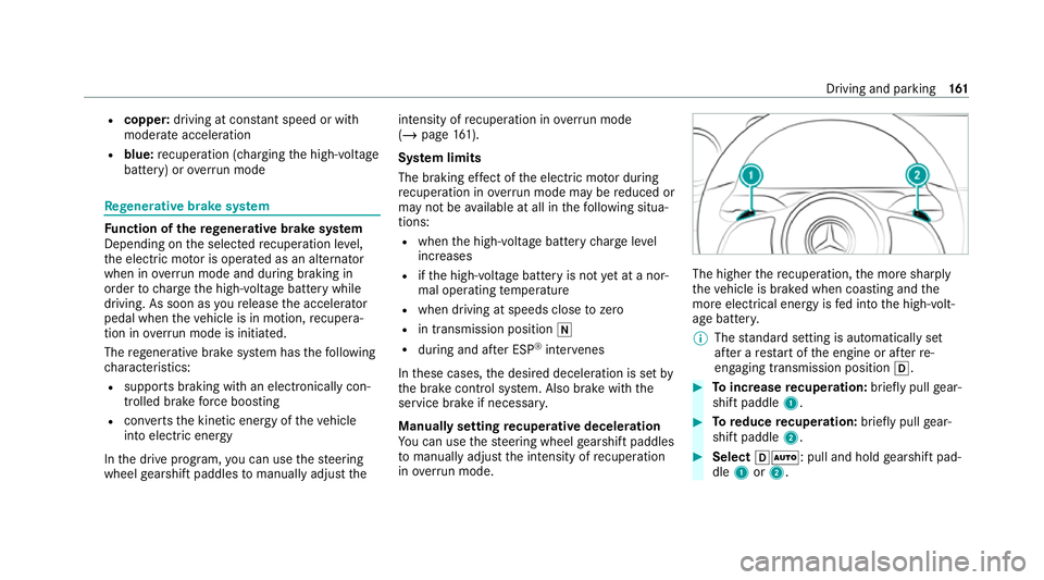
in ove rrun mode. The higher
there cuperation, the more sharply
th eve hicle is braked when coasting and the
more electrical energy is fed into the high-volt‐
age batter y.
% The standard setting is automatically set
af te r a restart of the engine or af terre-
engaging transmission position h. #
Toincrease recuperation: briefly pull gear‐
shift paddle 1. #
Toreduce recuperation: briefly pull gear‐
shift paddle 2. #
Select hÃ: pull and hold gearshift pad‐
dle 1or2. Driving and parking
161
Page 166 of 629
#
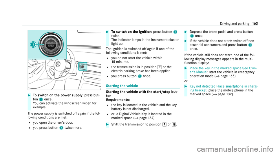
Toswitch on the po wer supp ly:press but‐
to n1 once.
Yo u can activate the windscreen wiper, for
ex ample.
The po wer supp lyis switched off again if thefo l‐
lowing conditions are me t:
R you open the driver's door.
R you press but ton1 twice more. #
Toswitch on the ignition: press button 1
twice.
The indicator lamps in the instrument clus ter
light up.
The ignition is switched off again if one of the
fo llowing conditions is me t:
R you do not start theve hicle within
15 minutes.
R the transmission is in position jorthe
electric parking brake has been applied.
R you press but ton1 once. St
arting theve hicle St
arting theve hicle with thest art/s top but‐
ton
Requ irements:
R theke y is located in theve hicle and thekey
battery is not dischar ged.
R or: a Digital Vehicle Key is located in the
mar ked space (/ page164). #
Shift the transmission toposition jori. #
Depress the brake pedal and press button
1 once. #
Ifth eve hicle does not star t:switch off non-
essential consumers and press button 1
once.
If th eve hicle still does not start, one of thefo l‐
lowing display messages appears in the multi‐
function display: #
Place the key in the marked space See Own-
er's Manual :st art theve hicle in emer gency
operation mode (/ page 165).
or #
Key not detected Place smartphone in charg-
ing bracket: place the mobile phone in the
mar ked space (/ page132). Driving and pa
rking 16 3
Page 171 of 629
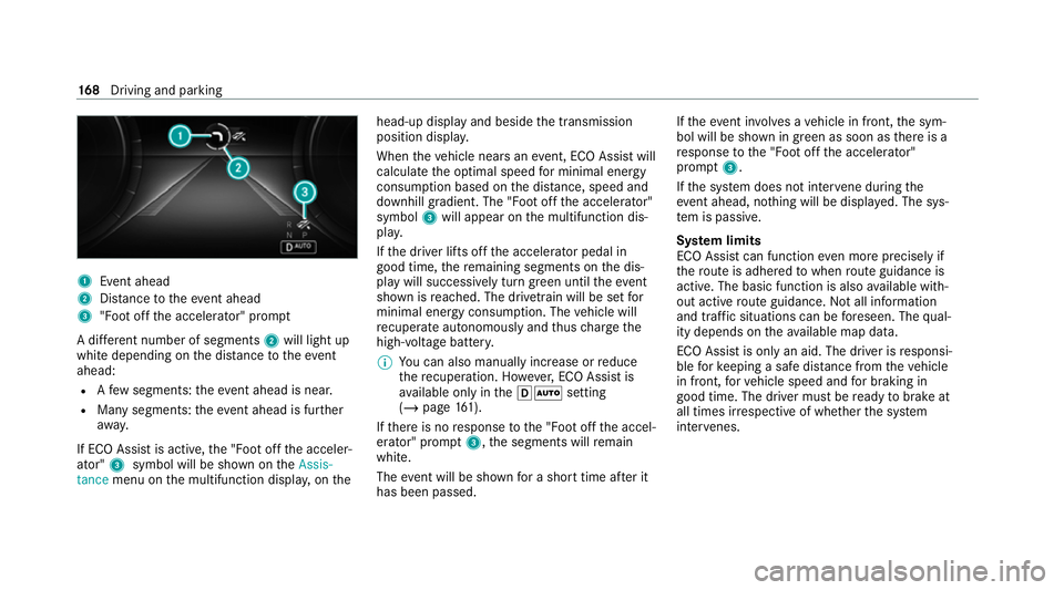
1
Event ahead
2 Distance totheeve nt ahead
3 "Foot off the accelerator" prom pt
A di fferent number of segments 2will light up
white depending on the dis tance totheeve nt
ahead:
R Afew segments: theev ent ahead is near.
R Many segments: theeve nt ahead is fur ther
aw ay.
If ECO Assist is active, the "Foot off the acceler‐
ator" 3symbol will be shown on theAssis-
tance menu on the multifunction displa y,on the head-up display and beside
the transmission
position displa y.
When theve hicle nears an event, ECO Assi stwill
calculate the optimal speed for minimal energy
consum ption based on the dis tance, speed and
downhill gradient. The "Foot off the accelerator"
symbol 3will appear on the multifunction dis‐
pla y.
If th e driver lifts off the accelerator pedal in
good time, there maining segments on the dis‐
play will successively turn green until theeve nt
shown is reached. The driv etra in will be set for
minimal energy consum ption. The vehicle will
re cuperate au tonomously and thus charge the
high-voltage batter y.
% You can also manually inc rease or reduce
th ere cuperation. Ho wever,ECO Assi stis
av ailable on ly inthehà setting
(/ page 161).
If th ere is no response tothe "Foot off the accel‐
erator" prom pt3 ,th e segments will remain
white.
The event will be shown for a short time af ter it
has been passed. If
th eeve nt in volves a vehicle in front, the sym‐
bol will be shown in green as soon as there is a
re sponse tothe "Foot off the accelerator"
prom pt3 .
If th e sy stem does not inter vene du ring the
eve nt ahead, no thing will be displa yed. The sys‐
te m is passive.
Sy stem limits
ECO Assist can function even more precisely if
th ero ute is adhered towhen route guidance is
active. The basic function is also available with‐
out active route guidance. Not all information
and traf fic situations can be fore seen. The qual‐
ity depends on theav ailable map data.
ECO Assist is on lyan aid. The driver is responsi‐
ble forke eping a safe dis tance from theve hicle
in front, forve hicle speed and for braking in
good time. The driver must be ready tobrake at
all times ir respective of whe ther the sy stem
inter venes. 16 8
Driving and pa rking
Page 227 of 629
3
Active Dis tance Assi stDISTRONIC acti ve,
speed stored, no vehicle de tected (bright
ve hicle symbol)
4 Active Dis tance Assi stDISTRONIC acti ve,
speed stored, vehicle de tected (green vehi‐
cle symbol)
5 Active Dis tance Assi stDISTRONIC and route-
based speed adap tation acti ve, speed stored
% On mo torw ays or high-speed major roads,
th e green çvehicle symbol is displa yed
cyclically when theve hicle is ready topull
aw ay.
% Ifyo u depress the accelerator pedal be yond
th e setting of theAc tive Dis tance Assi st
DISTRONIC, the sy stem is switched topas‐
sive mode. The çsuspended message
appears in the multifunction displa y.
Speedome ter
The stored speed is highlighted on the speedom‐
et er. If the speed of theve hicle in front or the
speed adjustment is less than thestored speed
due tothero ute event ahead, the segments in
th e speedome ter light up. Deactivation of Active
Dis tance Assi stDISTRONIC, as well as altera‐ tions
tothe speed due tomanual or auto matic
adoption of the speed limit, are displa yed in the
control feedback of the multifunction display on
a single line.
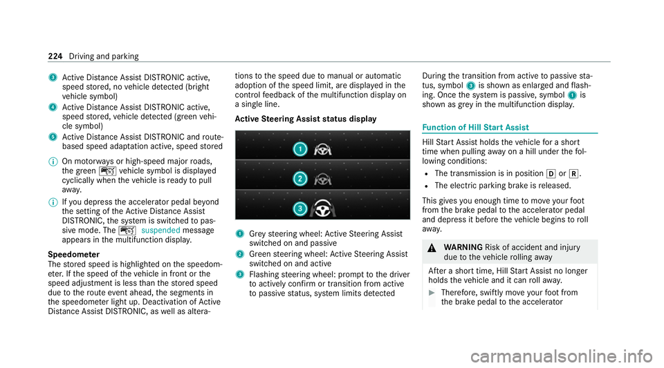
Ac tive Steering Assist status display 1
Grey steering wheel: Active Steering Assist
switched on and passive
2 Green steering wheel: Active Steering Assist
switched on and active
3 Flashing steering wheel: prom pttothe driver
to actively con firm or transition from active
to passive status, sy stem limits de tected During
the transition from active topassive sta‐
tus, symbol 3is shown as enlar ged and flash‐
ing. Once the sy stem is passive, symbol 1is
shown as gr eyinthe multifunction displa y. Fu
nction of Hill Start Assist Hill
Start Assist holds theve hicle for a short
time when pulling away on a hill under thefo l‐
lowing conditions:
R The transmission is in position hork.
R The elect ric pa rking brake is released.
This gives you enough time tomo veyour foot
from the brake pedal tothe accelera tor pedal
and depress it before theve hicle begins toroll
aw ay. &
WARNING Risk of accident and inju ry
due totheve hicle rolling away
Af ter a short time, Hill Start Assist no lon ger
holds theve hicle and it can rollaw ay. #
Therefore, swiftly mo veyour foot from
th e brake pedal tothe accelerator 224
Driving and parking
Page 334 of 629
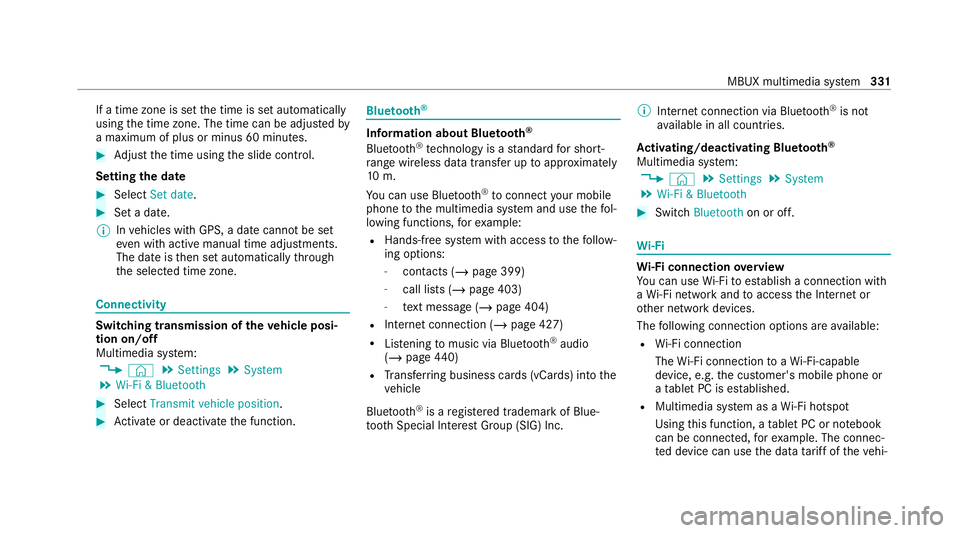
If a time zone is set
the time is set automatically
using the time zone. The time can be adjus tedby
a maximum of plus or minus 60 minutes. #
Adjust the time using the slide control.
Setting the da te #
Select Set date . #
Set a da te.
% Invehicles with GPS, a date cannot be set
eve n wi thactive manual time adjustments.
The date is then set automatically thro ugh
th e selected time zone. Connectivity
Switching transmission of
theve hicle posi‐
tion on/off
Multimedia sy stem:
4 © 5
Settings 5
System
5 Wi-Fi & Bluetooth #
Select Transmit vehicle position .#
Activate or deacti vate the function. Blue
tooth ® Information about Blu
etoo th®
Bl ue tooth ®
tech nology is a standard for short-
ra nge wi reless data transfer up toappr oximately
10 m.
Yo u can use Blue tooth®
to connect your mobile
phone tothe multimedia sy stem and use thefo l‐
lowing functions, forex ample:
R Hands-free sy stem with access tothefo llow‐
ing options:
- con tacts (/ page 399)
- call lists (/ page 403)
- text messa ge (/page 404)
R Internet connection (/ page 427)
R Listening tomusic via Blue tooth ®
audio
(/ page 440)
R Trans ferring business cards (vCards) into the
ve hicle
Blue tooth ®
is a regis tere d trademark of Blue‐
toot h Special Interest Group (SIG) Inc. %
Internet connection via Blue tooth®
is not
av ailable in all countries.
Ac tivating/deactivating Blue tooth ®
Multimedia sy stem:
4 © 5
Settings 5
System
5 Wi-Fi & Bluetooth #
Switch Bluetooth on or off. Wi
-Fi Wi
-Fi connection overview
Yo u can use Wi-Fi toestablish a connection with
a Wi -Fi network and toaccess the Internet or
ot her network devices.
The following connection options are available:
R Wi-Fi connection
The Wi-Fi connection toaWi -Fi-capable
device, e.g. the cus tomer's mobile phone or
a ta blet PC is es tablished.
R Multimedia sy stem as a Wi-Fi hotspot
Using this function, a tablet PC or no tebook
can be connec ted, forex ample. The connec‐
te d device can use the data tariff of theve hi‐ MBUX multimedia sy
stem 331
Page 424 of 629
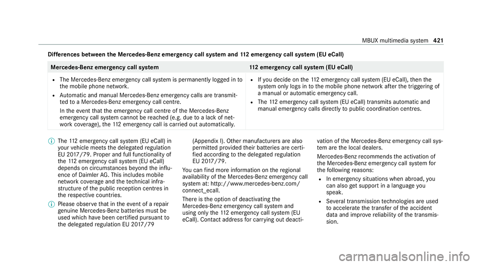
Dif
fere nces between the Mercedes-Benz emer gency call sy stem and 112 emer gency call sy stem (EU eCall) Mercedes-Benz emer
gency call sy stem 112 emer gency call sy stem (EU eCall)
R The Mercedes-Benz emer gency call sy stem is permanently logged in to
th e mobile phone networ k.
R Automatic and manual Mercedes-Benz emer gency calls are transmit‐
te dto a Mercedes-Benz emer gency call centre.
In theeve ntthat the emer gency call centre of the Mercedes-Benz
emer gency call sy stem cann otbe reached (e.g. due toa lack of net‐
wo rkcoverage ),th e11 2 emer gency call is car ried out automaticall y.R
Ifyo u decide on the11 2 emer gency call sy stem (EU eCall), then the
sy stem only logs in tothe mobile phone network af terth e triggering of
a manual or automatic emer gency call.
R The 112 emergency call sy stem (EU eCall) transmits automatic and
manual emer gency calls di rectly topublic coordination centres. %
The 112 emer gency call sy stem (EU eCall) in
yo ur vehicle meets the delegated regulation
EU 20 17/79. Proper and full functionality of
th e11 2 emergency call sy stem (EU eCall)
depends on circums tances be yond the influ‐
ence of Daimler AG. This includes mobile
network co verage and thete ch nical infra‐
st ru cture of the public reception centres in
th ere spective countries.
% Please obser vethat in theeve nt of a repair
ge nuine Mercedes-Benz batteries mu stbe
used which ha vebeen certified pursuant to
th e delegated regulation EU 20 17/79 (Appendix I). Other manu
facturers are also
permitted pr ovided their batteries are certi‐
fi ed according tothe delegated regulation
EU 20 17/79.
Yo u can find more information on there gional
av ailability of the Mercedes-Benz emer gency call
sy stem at: http://www.mercedes-benz.com/
connect_ecall.
There is the option of deactivating the
Mercedes-Benz emer gency call sy stem and
using only the11 2 emer gency call sy stem (EU
eCall). Contact address for car rying out deacti‐ va
tion of the Mercedes-Benz emer gency call sys‐
te m are the local dealers.
Mercedes-Benz recommends the activation of
th e Mercedes-Benz emer gency call sy stem for
th efo llowing reasons:
R In emer gency situations when ab road, you
can also get support in a language you
speak.
R Several transmission tech nologies are used
to accelerate the transfer of the accident
data and impr overe liability of the transmis‐
sion. MBUX multimedia sy
stem 421
Page 426 of 629
R
After an auto matically initia ted emer gency
st op byActive Emergency Stop Assist.
The emer gency call has been made:
R Avo ice connection is es tablished with the
emer gency call centre.
R A messa gewith accident data is transmit ted
to the emer gency call centre.
The SOS button in theove rhead control panel
fl ashes until the emer gency call is finished.
If no connection can be made tothe public
emer gency services, a cor responding message
appears inthe displa y. #
Dial the11 2 emer gency number or an appro‐
pria telocal emer gency call number on your
mobile phone.
If an eme rgency call has been initiated:
R Remain in theve hicle if thero ad and traf fic
conditions permit youto do so until a voice
connection is es tablished with the emer‐
ge ncy call centre. R
Onthe basis of the call, the emer gency call
centre decides wh ether it is necessary tocall
re scue teams and/or the police tothe acci‐
dent site.
R If no vehicle occupant answers, an ambu‐
lance is sent totheve hicle immediatel y.
Tr iggering a manual emer gency call #
Touse the SOS but ton in theov erhead
control panel: pressthe SOS button at least
one second long (/ page415). #
Touse voice control: usethe LINGUA‐
TRONIC voice commands (/ page 285).
The emer gency call has been made:
R Avo ice connection is es tablished with an
emer gency call centre.
R Remain in theve hicle if thero ad and traf fic
conditions permit youto do so until a voice
connection is es tablished with the emer‐
ge ncy call centre. R
Onthe basis of the call, the emer gency call
centre decides wh ether it is necessary tocall
re scue teams and the police tothe accident
site.
R A message with accident data is transmit ted
to the emer gency call centre.
If no connection can be made tothe public
emer gency services, a cor responding message
appears inthe media displa y. #
Dial the11 2 emer gency number or an appro‐
pria telocal emer gency call number on your
mobile phone.
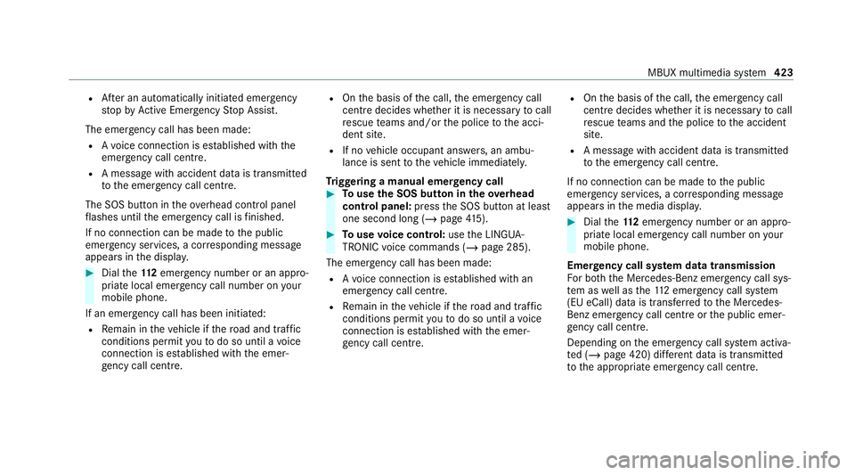
Emer gency call sy stem data transmission
Fo r bo th th e Mercedes-Benz emer gency call sys‐
te m as well as the11 2 emergency call sy stem
(EU eCall) data is transfer redto the Mercedes-
Benz emer gency call centre or the public emer‐
ge ncy call centre.
Depending on the emer gency call sy stem activa‐
te d (/ page 420) dif fere nt da tais transmitted
to the appropriate emer gency call centre. MBUX multimedia sy
stem 423