2019 MERCEDES-BENZ AMG GT ROADSTER run flat
[x] Cancel search: run flatPage 12 of 298
Electronic Traction System
see ETS (Electronic Traction System)
Emergency
Automatic measures after an acci-
dent ................................................ .55
Emergency braking
see BAS (Brake Assist System)
Emergency release
Driver's door .................................... 73
Trunk .............................................. .76
Vehicle .............................................73
Emergency Tensioning Devices
Activation ........................................ .52
Emissions control
Service and warranty information .... 25
Engine
Check Engine warning lamp .......... .204
Display message ............................ 187
ECO start/stop function ................ 113
Engine number ............................... 288
Irregular running ............................ 115
Jump-starting ................................. 256
Starting problems .......................... 115
Starting the engine with the
SmartKey ....................................... 112
Starting with the Start/Stop but-
ton ................................................. 112
Switching off .................................. 128
Tow-starting (vehicle) ..................... 261
Engine electronics
Notes ............................................. 287
Problem (malfunction) ................... 115
Engine oil
Adding .......................................... .238
Additives ........................................ 291
Checking the oil level ..................... 236
Checking the oil level using the
dipstick .......................................... 236
Checking the oil level using the
on-board computer ........................ 237
Display message ............................ 188
Filling capacity ............................... 291
Notes about oil grades ................... 291
Notes on oil level/consumption .... 236
Temperature (on-board com-
puter) ............................................. 170
Engine oil additives
see Additives (engine oil) Entering an address
see also Digital Operator's Man-
ual ................................................. .209
ESC (Electronic Stability Control)
see ESP ®
(Electronic Stability Program)
ESP ®
(Electronic Stability Pro-
gram)
AMG menu (on-board computer) ... 171
Characteristics ................................. 62
Deactivating/activating ................... 62
Deactivating/activating (button
in AMG vehicles) .............................. 63
Display message ............................ 175
Function/notes ................................ 62
General notes .................................. 62
Important safety information ........... 62
Warning lamp ................................. 201
ETS (Electronic Traction System) ....... 62
Exhaust check ................................... 131
Exhaust pipe (cleaning instruc-
tions) ................................................. .247
Exterior lighting
Cleaning ......................................... 246
see Lights
Exterior mirror
Calling up a stored setting (mem-
ory function) ................................... .95
Exterior mirrors
Adjusting ........................................ .92
Dipping (automatic) ........................ .93
Folding in/out (automatically )......... 92
Folding in/out (electrically) ............. 92
Out of position (troubleshooting) ..... 93
Setting ............................................. 92
Storing settings (memory func-
tion) ................................................. 94
Storing the parking position ............. 93 F
Favorites Overview ........................................ 212
Features ............................................. 220
Filler cap
see Refueling
Flat tire
Changing a wheel/mounting the
spare wheel ................................... 281 10
Index
Page 22 of 298
PSI (pounds per square inch) (def-
inition) ...........................................2 80
Replacing ....................................... 281
Service life ..................................... 264
Sidewall (definition) ....................... 280
Speed rating (definition) ................ 280
Storing .......................................... .282
Structure and characteristics
(definition) ..................................... 279
Summer tires in winter .................. 265
Temperature .................................. 275
TIN (Tire Identification Number)
(definition) ..................................... 281
Tire bead (definition) ..................... .280
Tire pressure (definition) ................ 280
Tire pressures (recommended) ...... 279
Tire size (data) ............................... 285
Tire size designation, load-bearing capacity, speed rating .................... 276
Tire tread ....................................... 264
Tire tread (definition) ..................... 280
Total load limit (definition) ............. 281
Traction ......................................... 275
Traction (definition) ....................... 281
Tread wea r..................................... 275
Uniform Tire Quality Grading
Standards ...................................... 274
Uniform Tire Quality Grading
Standards (definition) .................... 279
Wear indicator (definition) ............. 281
Wheel and tire combination ........... 285
Wheel rim (definition) .................... 279
see Flat tire
Tool
see Vehicle tool kit
Touchpad
Changing the station/music
track .............................................. 212
Character suggestions ................... 211
Deleting characters ....................... 211
Entering a space ............................ 211
Entering characters ....................... 211
Gesture control .............................. 211
Handwriting recognition ................ 211
Operating the touchpad ................. 211
Overview ........................................ 211
Quick access for Audio .................. 212
Switching ....................................... 211 Switching input line ....................... 211
Tow-starting
Emergency engine starting ............ 261
Towing
Permitted towing methods ............ 259
Towing away
Important safety guidelines ........... 258
Installing the towing eye ................ 259
Removing the towing eye ............... 260
Transporting the vehicle ................ 260
With both axles on the ground ....... 260
Towing eye ......................................... 249
Traction system
see ETS (Electronic Traction System)
Traffic reports
see also Digital Operator's Man-
ual .................................................. 209
Transmission
Driving tips .................................... 120
Selector lever ................................ 117
see Automatic transmission
Transmission position display ......... 119
Transmission positions
General notes ................................ 117
Overview ........................................ 118
Transporting the vehicle .................. 260
Trim pieces (cleaning instruc-
tions) .................................................. 247
Trip computer (on-board com-
puter) .................................................. 162
Trip odometer
Calling up ....................................... 161
Resetting (on-board computer) ...... 162
Trunk lid
Display message ............................ 196
Important safety notes .................... 74
Locking separately ........................... 76
Opening (automatically from
inside) .............................................. 75
Opening dimensions ...................... 293
Opening/closing (from the out-
side) ................................................. 74
Unlocking with KEYLESS-GO ............ 74
Trunk load (maximum) ...................... 293
Turn signals
Display message ............................ 186
Switching on/of f.............................. 97 20
Index
Page 133 of 298
X
Connect the cable provided in the trunk to the
trickle charger.
X Connect the trickle charger to 12 V socket 0043.
Consult the manufacturer's operating instruc- tions on how to do so.
The trunk lid can be closed, even if a trickle
charger is connected. Make sure that the con-
nector for both the connector cables is outside
of the vehicle.
The connector can then separate if the vehicle is moved, even if you forget to disconnect the con-
nector cables. This prevents damaging the
cables and the trickle charger.
A trickle charger connected to 12 V socket 0043
only maintains the current charge level of the
vehicle's electrical system battery. If the vehi-
cle's electrical system battery is discharged, it
needs to be charged with a battery charger. Driving tips
General driving tips
Important safety notes G
WARNING
If you switch off the ignition while driving,
safety-relevant functions are only available
with limitations, or not at all. This could affect, for example, the power steering and the brake
boosting effect. You will require considerably
more effort to steer and brake. There is a risk of an accident.
Do not switch off the ignition while driving. G
WARNING
If you operate mobile communication equip-
ment when driving, you may be distracted
from the traffic situation. You could also lose
control of the vehicle. There is a risk of an
accident.
Only operate this equipment when the vehicle is stationary.
Observe the legal requirements for the country
in which you are driving. Some jurisdictions pro-
hibit the driver from using a mobile phone while driving a vehicle. If you make a call while driving, always use
hands-free mode. Only operate the telephone
when the traffic situation permits. If you are
unsure, pull over to a safe location and stop
before operating the telephone.
Bear in mind that at a speed of only 30 mph
(approximately 50 km/h), the vehicle covers a
distance of 44 ft (approximately 14
m)per sec-
ond.
Drive sensibly – save fuel Observe the following tips to save fuel:
X The tires should always be inflated to the rec-
ommended tire pressure.
X Remove unnecessary loads.
X Warm up the engine at low engine speeds.
X Avoid frequent acceleration or braking.
X Have all service and maintenance work car-
ried out at the specified intervals.
Fuel consumption also increases when driving in
cold weather, in stop-start traffic and in hilly ter- rain.
Drinking and driving G
WARNING
Drinking and driving and/or taking drugs and driving are very dangerous combinations.
Even a small amount of alcohol or drugs can
affect your reflexes, perceptions and judg-
ment.
The possibility of a serious or even fatal acci-
dent is greatly increased when you drink or
take drugs and drive.
Do not drink or take drugs and drive or allow
anyone to drive who has been drinking or tak-
ing drugs.
Emission control G
DANGER
Combustion engines emit poisonous exhaust
gases such as carbon monoxide. Inhaling
these exhaust gases is hazardous to health
and can result in poisoning. There is a risk of
fatal injury. Therefore, never leave the engine Driving tips
131Driving and parking
Z
Page 252 of 298
R
lug wrench
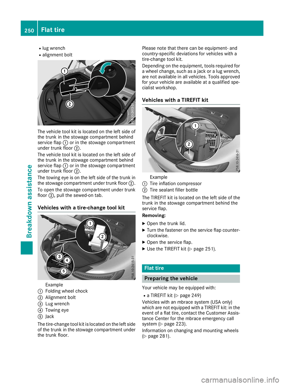
R alignment bolt The vehicle tool kit is located on the left side of
the trunk in the stowage compartment behind
service flap 0043or in the stowage compartment
under trunk floor 0044.
The vehicle tool kit is located on the left side of the trunk in the stowage compartment behind
service flap 0043or in the stowage compartment
under trunk floor 0044.
The towing eye is on the left side of the trunk in
the stowage compartment under trunk floor 0044.
To open the stowage compartment under trunk floor 0044, pull the sewed-on tab.
Vehicles with a tire-change tool kit Example
0043 Folding wheel chock
0044 Alignment bolt
0087 Lug wrench
0085 Towing eye
0083 Jack
The tire-change tool kit is located on the left side of the trunk in the stowage compartment under the trunk floor. Please note that there can be equipment- and
country-specific deviations for vehicles with a
tire-change tool kit.
Depending on the equipment, tools required for
a wheel change, such as a jack or a lug wrench, are not available in all vehicles. Tools approved
for your vehicle are available at a qualified spe-
cialist workshop.
Vehicles with a TIREFIT kit Example
0043 Tire inflation compressor
0044 Tire sealant filler bottle
The TIREFIT kit is located on the left side of the
trunk in the stowage compartment behind the
service flap.
Removing:
X Open the trunk lid.
X Turn the fastener on the service flap counter-
clockwise.
X Open the service flap.
X Use the TIREFIT kit (Y page 251). Flat tire
Preparing the vehicle
Your vehicle may be equipped with: R a TIREFIT kit (Y page 249)
Vehicles with an mbrace system (USA only)
which are not equipped with a TIREFIT kit: in the event of a flat tire, contact the Customer Assis-
tance Center for the mbrace emergency call
system (Y page 223).
Information on changing and mounting wheels
(Y page 281). 250
Flat tireBreakdown assistance
Page 253 of 298
X
Stop the vehicle on solid, non-slippery and
level ground, as far away as possible from
traffic.
X Switch on the hazard warning lamps.
X Secure the vehicle against rolling away
(Y page 127).
X If possible, bring the front wheels into the
straight-ahead position.
X Switch off the engine.
X With KEYLESS-GO start function or vehi-
cles with KEYLESS-GO: open the driver's
door.
The vehicle electronics are now in key posi-
tion 0092. This is the same as the key having
been removed.
or X Remove the SmartKey from the ignition lock.
X Make sure that the passengers are not endan-
gered as they do so. Make sure that no one is
near the danger area while a wheel is being
changed. Anyone who is not directly assisting in the wheel change should, for example,
stand behind the barrier.
X Get out of the vehicle. Pay attention to traffic
conditions when doing so.
X Close the driver's door. TIREFIT kit
Important safety notes TIREFIT is a tire sealant.
You can use TIREFIT to seal punctures of up to
0.16 in (4 mm), particularly those in the tire
tread. You can use TIREFIT at outside tempera-
tures down to 00F84 ‡ (00F820 †). G
WARNING
In the following situations, the tire sealant is
unable to provide sufficient breakdown assis- tance, as it is unable to seal the tire properly:
R there are cuts or punctures in the tire larger
than those mentioned above.
R the wheel rim is damaged.
R you have driven at very low tire pressures or
on a flat tire.
There is a risk of an accident.
Do not drive the vehicle. Contact a qualified
specialist workshop. G
WARNING
The tire sealant is harmful and causes irrita-
tion. It must not come into contact with your
skin, eyes or clothing or be swallowed. Do not inhale TIREFIT fumes. Keep tire sealant away
from children. There is a risk of injury.
If you come into contact with the tire sealant,
observe the following:
R Rinse off the tire sealant from your skin
immediately with water.
R If the tire sealant comes into contact with
your eyes, immediately rinse them thor-
oughly with clean water.
R If tire sealant is swallowed, immediately
rinse your mouth out thoroughly and drink
plenty of water. Do not induce vomiting,
and seek medical attention immediately.
R Immediately change out of clothing which
has come into contact with tire sealant.
R If an allergic reaction occurs, seek medical
attention immediately.
! Do not operate the tire inflation compressor
for longer than ten minutes at a time without a break. It may otherwise overheat.
The tire inflation compressor can be operatedagain once it has cooled down.
Comply with the manufacturer's safety instruc-
tions on the tire inflation compressor label and
on the tire sealant bottle.
Using the TIREFIT kit X
Do not remove any foreign objects which have
penetrated the tire, e.g. screws or nails.
X Remove the tire sealant bottle, the accompa-
nying TIREFIT sticker and the tire inflation
compressor from the stowage compartment
in the trunk (Y page 249). Flat tire
251Breakdown assistance Z
Page 254 of 298
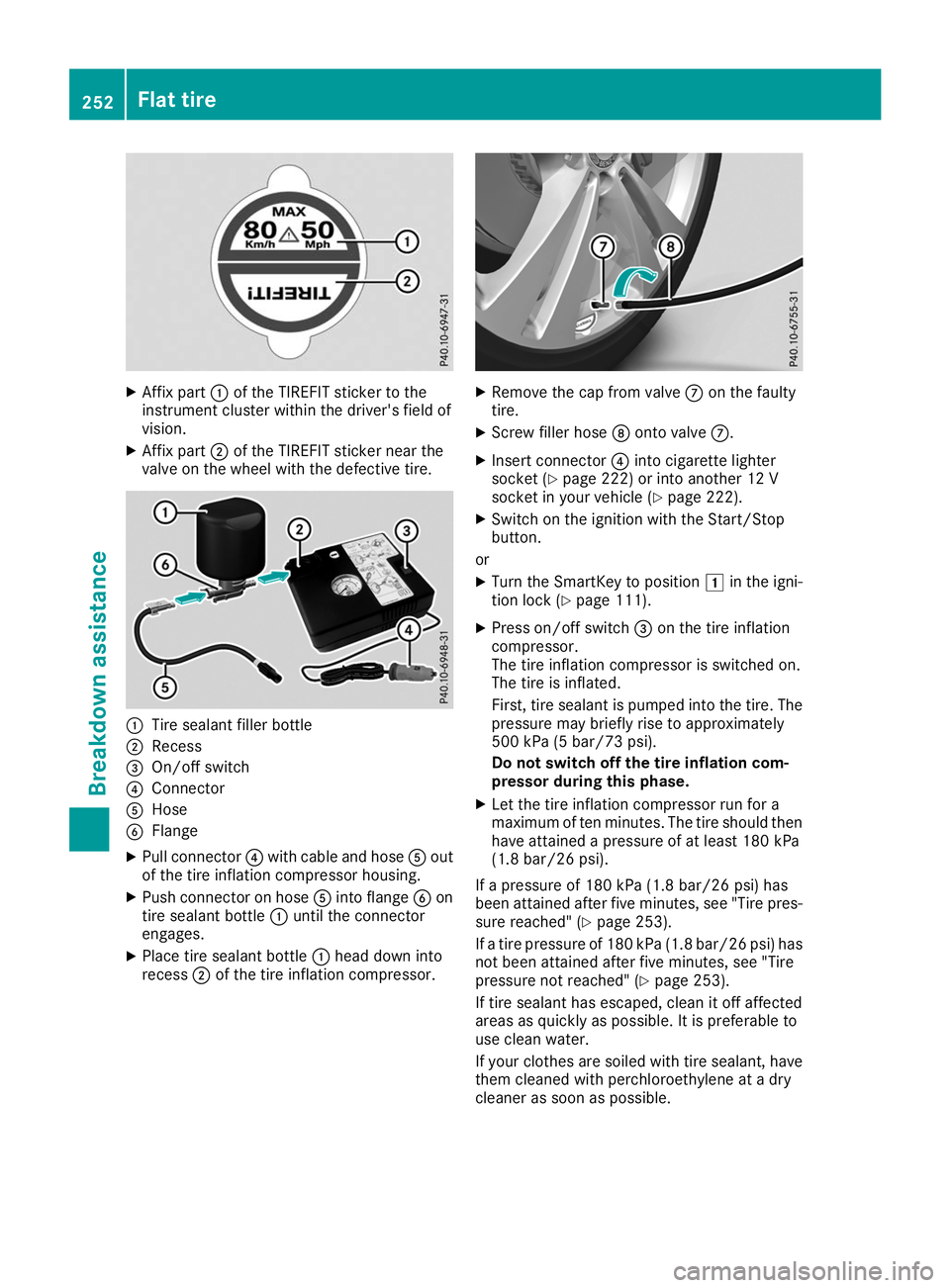
X
Affix part 0043of the TIREFIT sticker to the
instrument cluster within the driver's field of
vision.
X Affix part 0044of the TIREFIT sticker near the
valve on the wheel with the defective tire. 0043
Tire sealant filler bottle
0044 Recess
0087 On/off switch
0085 Connector
0083 Hose
0084 Flange
X Pull connector 0085with cable and hose 0083out
of the tire inflation compressor housing.
X Push connector on hose 0083into flange 0084on
tire sealant bottle 0043until the connector
engages.
X Place tire sealant bottle 0043head down into
recess 0044of the tire inflation compressor. X
Remove the cap from valve 006Bon the faulty
tire.
X Screw filler hose 006Conto valve 006B.
X Insert connector 0085into cigarette lighter
socket (Y page 222) or into another 12 V
socket in your vehicle (Y page 222).
X Switch on the ignition with the Start/Stop
button.
or X Turn the SmartKey to position 0047in the igni-
tion lock (Y page 111).
X Press on/off switch 0087on the tire inflation
compressor.
The tire inflation compressor is switched on.
The tire is inflated.
First, tire sealant is pumped into the tire. The
pressure may briefly rise to approximately
500 kPa (5 bar/73 psi).
Do not switch off the tire inflation com-
pressor during this phase.
X Let the tire inflation compressor run for a
maximum of ten minutes. The tire should then have attained a pressure of at least 180 kPa
(1.8 bar/26 psi).
If a pressure of 180 kPa (1.8 ba r/26 psi) has
been at tained after five minutes, see "Tire pres-
sure reached" (Y page 253).
If a tire pressure of 180 kPa (1.8 bar/26 psi) has not been attained after five minutes, see "Tire
pressure not reached" (Y page 253).
If tire sealant has escaped, clean it off affected
areas as quickly as possible. It is preferable to
use clean water.
If your clothes are soiled with tire sealant, have them cleaned with perchloroethylene at a dry
cleaner as soon as possible. 252
Flat tireBreakdown assistance
Page 265 of 298
Important safety notes
G
WARNING
If wheels and tires of the wrong size are used, the wheel brakes or suspension components
may be damaged. There is a risk of an acci-
dent.
Always replace wheels and tires with those
that fulfill the specifications of the original
part.
When replacing wheels, make sure to use the
correct:
R designation
R model
When replacing tires, make sure to use the
correct:
R designation
R manufacturer
R model G
WARNING
A flat tire severely impairs the driving, steer-
ing and braking characteristics of the vehicle.
There is a risk of accident.
Tires without run-flat characteristics:
R do not drive with a flat tire.
R immediately replace the flat tire with your
emergency spare wheel or spare wheel, or
consult a qualified specialist workshop.
Tires with run-flat characteristics:
R pay attention to the information and warn-
ing notices on MOExtended tires (tires with
run-flat characteristics).
Accessories that are not approved for your vehi-
cle by Mercedes-Benz or are not being used cor- rectly can impair the operating safety.
Before purchasing and using non-approved
accessories, visit a qualified specialist work-
shop and inquire about:
R suitability
R legal stipulations
R factory recommendations Information on the sizes and types of wheels and
tires for your vehicle can be found under
"Wheel/tire combinations" (Y page 285).
Tire pressure information can be found:
R on the Tire and Loading Information placard
on the B-pillar on the driver's side
(Y page 271)
R in the tire pressure table in the fuel filler flap
(Y page 126)
R in the "Tire pressure" section Operation
Information on driving
Check the tire pressure when the vehicle is
heavily laden and adjust prior to a trip.
While driving, pay attention to vibrations, noises
and unusual handling characteristics, e.g. pull-
ing to one side. This may indicate that the
wheels or tires are damaged. If you suspect that a tire is defective, reduce your speed immedi-
ately. Stop the vehicle as soon as possible to
check the wheels and tires for damage. Hidden
tire damage could also be causing the unusual
handling characteristics. If you find no signs of
damage, have the tires and wheels checked at a
qualified specialist workshop.
When parking your vehicle, make sure that the
tires do not get deformed by the curb or other
obstacles. If they cannot be avoided, drive over obstacles such as curbs slowly and at an obtuse
angle. Otherwise, you may damage the wheels
or tires. Notes on high performance tires
G
WARNING
Due to the special tire tread in combination
with the optimized rubber compound, there is an increased risk of hydroplaning and skid-
ding on damp or wet road surfaces. In addi-
tion, tire traction is significantly reduced at
low outside temperatures and low tire-oper-
ating temperatures. There is a risk of an acci-
dent.
Activate ESP ®
and adapt your driving style. At
outside temperatures below 50 ‡(10 †), use
M+S tires. Operation
263Wheels and tires Z
Page 285 of 298
R
Before raising the vehicle, secure it from roll-
ing away by applying the parking brake and
inserting wheel chocks. Do not disengage the parking brake while the vehicle is raised.
R The jack must be placed on a firm, flat and
non-slip surface. On a loose surface, a large,
flat, load-bearing underlay must be used. On a slippery surface, a non-slip underlay must be
used, e.g. rubber mats.
R Do not use wooden blocks or similar objects
as a jack underlay. Otherwise, the jack will not
be able to achieve its load-bearing capacity
due to the restricted height.
R Make sure that the distance between the
underside of the tires and the ground does not
exceed 1.2 in (3 cm).
R Do not place your hands or feet under the
raised vehicle.
R Do not lie under the vehicle.
R Do not start the engine when the vehicle is
raised.
R Do not open or close a door or the trunk lid
when the vehicle is raised.
R Make sure that no persons are present in the
vehicle when the vehicle is raised.
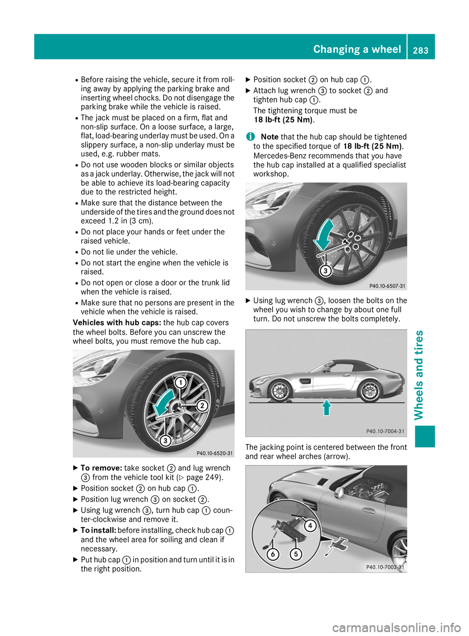
Vehicles with hub caps: the hub cap covers
the wheel bolts. Before you can unscrew the
wheel bolts, you must remove the hub cap. X
To remove: take socket0044and lug wrench
0087 from the vehicle tool kit (Y page 249).
X Position socket 0044on hub cap 0043.
X Position lug wrench 0087on socket 0044.
X Using lug wrench 0087, turn hub cap0043coun-
ter-clockwise and remove it.
X To install: before installing, check hub cap 0043
and the wheel area for soiling and clean if
necessary.
X Put hub cap 0043in position and turn until it is in
the right position. X
Position socket 0044on hub cap 0043.
X Attach lug wrench 0087to socket 0044and
tighten hub cap 0043.
The tightening torque must be
18 lb-ft (25 Nm).
i Note
that the hub cap should be tightened
to the specified torque of 18 lb-ft (25 Nm).
Mercedes-Benz recommends that you have
the hub cap installed at a qualified specialist
workshop. X
Using lug wrench 0087, loosen the bolts on the
wheel you wish to change by about one full
turn. Do not unscrew the bolts completely. The jacking point is centered between the front
and rear wheel arches (arrow). Changing a wheel
283Wheels and tires Z