2019 MERCEDES-BENZ AMG GT ROADSTER steering
[x] Cancel search: steeringPage 228 of 298
The system was unable to initiate an Info call if:
R the indicator lamp in the 00D9Info call button
is flashing continuously.
R no voice connection to the Mercedes-Benz
Customer Assistance Center has been estab-
lished.
This can occur if the relevant mobile phone net-
work is not available, for example.
The Call Failed
Call Failed message appears in the mul-
tifunction display.
X To end a call: press the0076button on the
multifunction steering wheel.
or X Press the corresponding multimedia system
button for ending a phone call.
Call priority When service calls are active, e.g. Roadside
Assistance or Info calls, an emergency call can
still be initiated. In this case, an emergency call
will take priority and override all other active
calls.
The indicator lamp of the respective button
flashes until the call is ended.
An emergency call can only be terminated by the
Mercedes-Benz Customer Assistance Center.
All other calls can be ended by pressing:
R the 0076 button on the multifunction steering
wheel
R the corresponding button in the multimedia
system to end the voice call
When a call is initiated, the audio system is
muted.
The mobile phone is no longer connected to the multimedia system.
However, if you want to use your mobile phone,
do so only when the vehicle is stationary and in a safe location.
Downloading destinations in COMAND Downloading destinations
Downloading destinations gives you access to a database with over 15 million points of interest
(POIs). These can be downloaded on the navi-
gation system in your vehicle. If you know the
destination, the address can be downloaded.
Alternatively, you can obtain the location of
Points of Interest (POIs)/important destinations in the vicinity. Furthermore, you can download routes with up
to four way points.
You are prompted to confirm route guidance to
the address entered.
X SelectYes Yesby turning 3or sliding 1
the controller and confirm with 7.
The system calculates the route and subse-
quently starts the route guidance with the
address entered.
If you select No Nothe address can be stored in
the address book.
The destination download function is available
if: R the vehicle is equipped with a navigation sys-
tem.
R the relevant mobile phone network is availa-
ble and data transfer is possible.
Route Assistance This service is part of the mbrace PLUS Packageand cannot be purchased separately.
You can use the Route Assistance function even
if the vehicle is not equipped with a navigation
system.
Within the framework of this service, you receive a professional and reliable form of navigation
support without having to leave your vehicle.
The customer service representative finds a
suitable route depending on your vehicle's cur-
rent position and the desired destination. You
will then be guided live through the current route section.
Search and Send General notes
To use "Search & Send", your vehicle must be
equipped with mbrace and a navigation system. Additionally, an mbrace service subscription
must be completed.
"Search & Send" is a service for entering desti-
nations in the navigation system. A destination
address which is found on Google Maps ®
can be
transferred via mbrace directly to your vehicle's navigation system. 226
FeaturesStowage and features
Page 239 of 298
X
Pull oil dipstick 0043out of the dipstick guide
tube.
X Wipe off oil dipstick 0043. X
Slowly slide oil dipstick 0043into the guide tube
to the stop, and take it out again.
If the level is between MIN mark 0087and MAX
mark 0044, the oil level is correct.
X If the oil level has dropped to MIN mark 0087or
below, add 1.1 US qt (1.0 liter) engine oil.
Checking the oil level using the on-board computer Calling up the oil level measurement
X Select key position 0048with the Start/Stop button.
X Use 00E2 on the steering wheel to call up the list of menus.
X Press the 0064or0063 button on the steering wheel to select the Service
Service menu.
X Confirm by pressing 0076on the steering wheel.
X Use 0064 or0063 to select the Engine Oil Level
Engine Oil Level submenu.
X Press 0076to confirm the selection.
The Measuring Engine Oil Level Accurate Only When Vehicle Is Level
Measuring Engine Oil Level Accurate Only When Vehicle Is Level message
appears in the multifunction display.
The measurement takes a few seconds. You will see a message in the multifunction display. The
messages are explained in the following chapter.
Engine oil level display messages Display messages
Possible causes/consequences and
0050 0050Solutions Engine Oil Level OK
Engine Oil Level OK The engine oil level is correct.
Check Engine Oil
Check Engine Oil
Level (Add 1 Liter) Level (Add 1 Liter) The engine oil level is too low.
X Add 1.1 US qt (1.0 liter) of engine oil. Reduce Engine Oil
Reduce Engine Oil
Level Level The engine oil level is too high.
X Have excess engine oil siphoned off. For Engine Oil
For Engine Oil
Level Level
Ignition
Ignition Must
Must
Be On
Be On The ignition is switched off.
X Select key position 0048with the Start/Stop button. Need More Time to
Need More Time to
Check Engine Oil Check Engine Oil
Level Level The required waiting period was not observed.
X The engine must be at regular operating temperature.
Measurements can only be taken within the first four minutes after
the engine has been switched off. Engine Oil Level
Engine Oil Level
Not Not
Measurable
Measurable with
with
Engine Running
Engine Running The engine is running; oil level measurement is not possible.
X Switch off the engine.
X Repeat the measurement. Observe the required waiting period. Engine compartment
237Maintenance and care Z
Page 243 of 298
Hiding a service message
X Press the 0076or0038 button on the steering
wheel. Displaying service messages
X Switch on the ignition.
X Use 00E2 on the steering wheel to call up the
list of menus.
X Press 0063or0064 on the steering wheel to
select the Service Servicemenu and confirm with
0076.
X Press 0063or0064 on the steering wheel to
select the ASSYST PLUS
ASSYST PLUS submenu and con-
firm with 0076.
The service due date appears in the multi-
function display. Information about Service
Resetting the ASSYST PLUS service
interval display !
If the ASSYST PLUS service interval display
has been inadvertently reset, this setting can
be corrected at a qualified specialist work-
shop.
Have service work carried out as described in the Maintenance Booklet. This may otherwise
lead to increased wear and damage to the
major assemblies or the vehicle.
A qualified specialist workshop, e.g. an author-
ized Mercedes-Benz Service Center, will reset
the ASSYST PLUS service interval display after
the service work has been carried out. You can
also obtain further information on maintenance work, for example.
Special service requirements The specified maintenance interval takes only
the normal operation of the vehicle into
account. Under arduous operating conditions or
increased load on the vehicle, maintenance
work must be carried out more frequently, for
example:
R Regular city driving with frequent intermedi-
ate stops
R If the vehicle is primarily used to travel short
distances R
Use in mountainous terrain or on poor road
surfaces
R If the engine is often left idling for long periods
R In racetrack mode
Under these or similar conditions, have, for
example, the air filter, engine oil and oil filter
replaced or changed more frequently. Under
arduous operating conditions, the tires must be
checked more often. Further information can be
obtained at a qualified specialist workshop, e.g. an authorized Mercedes-Benz Service Center.
i In racetrack mode, the vehicle is subject to
higher loads, meaning that additional main-
tenance work is required. If you plan race-
track use, consult a qualified specialist work-
shop first. Mercedes-Benz recommends that
you use an authorized Mercedes-Benz Ser-
vice Center for this purpose.
Driving abroad An extensive Mercedes-Benz Service network is
also available in other countries. You can obtain further information from any authorized
Mercedes-Benz Service Center. Care
General notes
H
Environmental note
Dispose of empty packaging and cleaning
cloths in an environmentally responsible man-
ner.
! When cleaning your car, do not use:
R dry, coarse or hard cloths
R abrasive cleaning agents
R solvents
R cleaning agents containing solvents
Do not scrub.
Do not touch the surfaces and films with hard
objects, e.g. rings or ice scrapers. Otherwise,
you may scratch or damage the surfaces and films.
! Do not park your vehicle for a long period of
time directly after cleaning, particularly after
cleaning the wheel rim with wheel cleaner.
Wheel cleaner can lead to the increased cor-
rosion of the brake discs and pads. Therefore, Care
241Maintenance and care Z
Page 249 of 298
Cleaning the exhaust pipe
G
WARNING
The exhaust tail pipe and tail pipe trim can
become very hot. If you come into contact
with these parts of the vehicle, you could burn
yourself. There is a risk of injury.
Always be particularly careful around the
exhaust tail pipe and the tail pipe trim. Allow
these components to cool down before touch-
ing them.
! Do not clean the exhaust pipe with acid-
based cleaning agents, such as bathroom
cleaner or wheel cleaner.
! Vehicles with black exhaust pipes: black
chromed screens should not be polished with
a chrome polish. They will otherwise lose their black shine. For optimal care, the screens
should be rubbed with a lightly oiled cloth
after every car wash. Commercially available
engine and care oils are suitable for this.
For heavier soiling, you can apply a fine paint- work polish with a microfiber cloth. Remove
the excess polish residue after polishing.
X Clean the exhaust pipe with a chrome care
product tested and approved by Mercedes-
Benz.
Impurities combined with the effects of road grit
and corrosive environmental factors may cause flash rust to form on the surface. You can
restore the original shine of the exhaust pipe by
cleaning it regularly, especially in winter and
after washing. Interior care
Cleaning the display !
For cleaning, do not use any of the following:
R alcohol-based thinner or gasoline
R abrasive cleaning agents
R commercially-available household cleaning
agents
These may damage the display surface. Do
not put pressure on the display surface when
cleaning. This could lead to irreparable dam-
age to the display. X
Before cleaning the display, make sure that it
is switched off and has cooled down.
X Clean the display surface using a commer-
cially available microfiber cloth and TFT/LCD
display cleaner.
X Dry the display surface using a dry microfiber
cloth.
Cleaning the plastic trim G
WARNING
Care products and cleaning agents containing solvents cause surfaces in the cockpit to
become porous. As a result, plastic parts may
come loose in the event of air bag deploy-
ment. There is a risk of injury.
Do not use any care products and cleaning
agents to clean the cockpit.
! Never attach the following to plastic surfa-
ces:
R stickers
R films
R perfume oil container or similar
You could otherwise damage the plastic.
! Do not allow cosmetics, insect repellent or
sunscreen to come into contact with the plas-
tic trim. This maintains the high-quality look of the surfaces.
X Wipe the plastic trim with a damp, lint-free
cloth, e.g. a microfiber cloth.
X Heavy soiling: use care and cleaning prod-
ucts recommended and approved by
Mercedes-Benz.
The surface may change color temporarily.
Wait until the surface is dry again.
Cleaning the steering wheel and gear or selector lever X
Thoroughly wipe with a damp cloth or use
leather care agents that have been recom-
mended and approved by Mercedes-Benz.
Cleaning the trim elements !
Do not use solvent-based cleaning agents
such as tar remover, wheel cleaners, polishes
or waxes. There is otherwise a risk of damag- ing the surface. Care
247Maintenance and care Z
Page 256 of 298
X
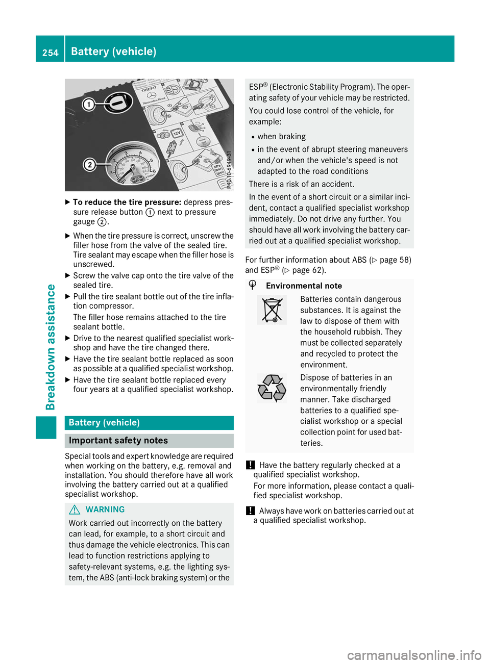
To reduce the tire pressure: depress pres-
sure release button 0043next to pressure
gauge 0044.
X When the tire pressure is correct, unscrew the
filler hose from the valve of the sealed tire.
Tire sealant may escape when the filler hose is unscrewed.
X Screw the valve cap onto the tire valve of the
sealed tire.
X Pull the tire sealant bottle out of the tire infla-
tion compressor.
The filler hose remains attached to the tire
sealant bottle.
X Drive to the nearest qualified specialist work-
shop and have the tire changed there.
X Have the tire sealant bottle replaced as soon
as possible at a qualified specialist workshop.
X Have the tire sealant bottle replaced every
four years at a qualified specialist workshop. Battery (vehicle)
Important safety notes
Special tools and expert knowledge are required
when working on the battery, e.g. removal and
installation. You should therefore have all work
involving the battery carried out at a qualified
specialist workshop. G
WARNING
Work carried out incorrectly on the battery
can lead, for example, to a short circuit and
thus damage the vehicle electronics. This can lead to function restrictions applying to
safety-relevant systems, e.g. the lighting sys- tem, the ABS (anti-lock braking system) or the ESP
®
(Electronic Stability Program). The oper-
ating safety of your vehicle may be restricted.
You could lose control of the vehicle, for
example:
R when braking
R in the event of abrupt steering maneuvers
and/or when the vehicle's speed is not
adapted to the road conditions
There is a risk of an accident.
In the event of a short circuit or a similar inci-
dent, contact a qualified specialist workshop
immediately. Do not drive any further. You
should have all work involving the battery car- ried out at a qualified specialist workshop.
For further information about ABS (Y page 58)
and ESP ®
(Y page 62). H
Environmental note Batteries contain dangerous
substances. It is against the
law to dispose of them with
the household rubbish. They
must be collected separately
and recycled to protect the
environment. Dispose of batteries in an
environmentally friendly
manner. Take discharged
batteries to a qualified spe-
cialist workshop or a special
collection point for used bat-
teries.
! Have the battery regularly checked at a
qualified specialist workshop.
For more information, please contact a quali- fied specialist workshop.
! Always have work on batteries carried out at
a qualified specialist workshop. 254
Battery (vehicle)Breakdo
wn assis tance
Page 260 of 298
X
Start the engine of your own vehicle.
X Let the engines run for several minutes.
X Before disconnecting the jumper cables, switch on an electrical consumer in your own vehicle,
e.g. the rear window heating or the lighting.
X When the jump-starting procedure is finished: first, remove the jumper cables from ground
point 0085and from negative terminal 0087of the donor battery, and then from positive terminal 0043
and positive terminal 0044of the donor battery. Begin each time at the contacts on your own vehicle
first.
X After removing the jumper cables, close cover 0083of positive terminal 0043.
X Only for vehicles with a carbon-fiber engine cover: insert the cover of the jump-starting
connection point. Make sure all mountings for the fasteners are positioned precisely behind the corresponding recesses in the cover.
Press the fasteners into the mountings. Turn the fasteners by 00C4of a turn to engage.
X Have the battery checked at a qualified specialist workshop.
Jump-starting is not considered to be a normal operating condition.
i Jumper cables and further information regarding jump-starting can be obtained at a qualified
specialist workshop. Towing and tow-starting
Important safety notes
G
WARNING
The rear axle locks when:
R the engine is not running
R the engine stalls while the vehicle is being
towed
R there is a malfunction in the power supply
or the vehicle's electrical system
There is a risk of an accident.
In the event of a breakdown, you should
always have the vehicle transported. G
WARNING
If the brake system or power steering is mal-
functioning and your vehicle is then towed
away, significantly more effort may be
required to steer and brake than is normally
required. There is a risk of an accident.
In such cases, use a tow bar. Before towing,
make sure that the steering moves freely. G
WARNING
When towing or tow-starting another vehicle
and its weight is greater than the permissible gross weight of your vehicle, the:
R the towing eye could detach itself
R the vehicle/trailer combination could roll-
over.
There is a risk of an accident.
When towing or tow-starting another vehicle,
its weight should not be greater than the per- missible gross weight of your vehicle.
Details on the permissible gross vehicle weight
of your vehicle can be found on the vehicle iden-
tification plate (Y page 287).
! Use the SmartKey instead of the Start/Stop
button when towing the vehicle.
Start the engine and keep it running. The
SmartKey is in position 0048in the ignition lock.
Set the transmission to 005Cusing the E-
SELECT selector lever. Make sure that you
then leave the SmartKey in position 0048.
Check the transmission position in the instru-
ment cluster.
! Make sure that the electric parking brake is
released. If the electric parking brake is faulty,
visit a qualified specialist workshop. 258
Towing and tow-startingBreakdown assistance
Page 262 of 298
X
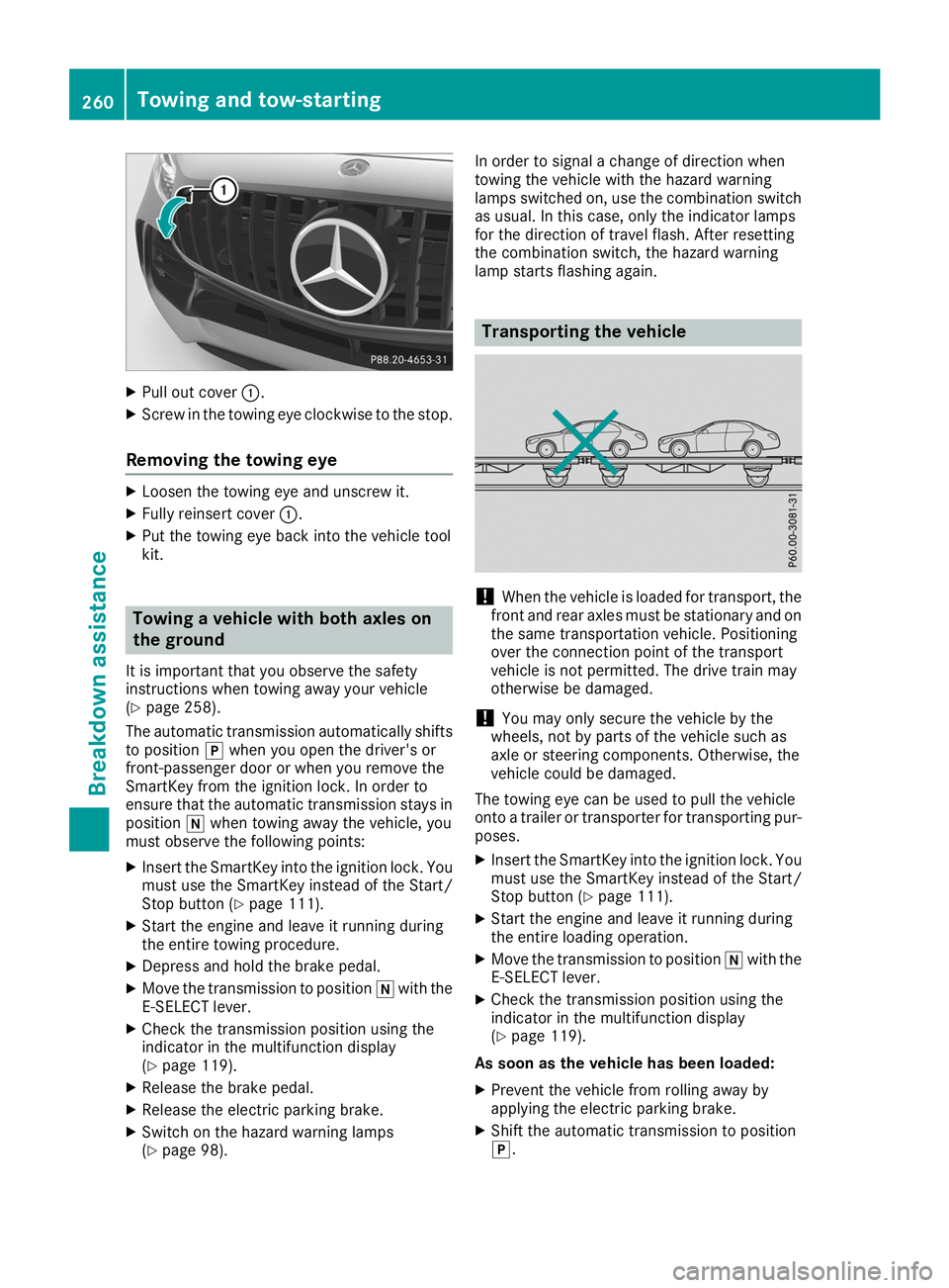
Pull out cover 0043.
X Screw in the towing eye clockwise to the stop.
Removing the towing eye X
Loosen the towing eye and unscrew it.
X Fully reinsert cover 0043.
X Put the towing eye back into the vehicle tool
kit. Towing a vehicle with both axles on
the ground
It is important that you observe the safety
instructions when towing away your vehicle
(Y page 258).
The automatic transmission automatically shifts
to position 005Dwhen you open the driver's or
front-passenger door or when you remove the
SmartKey from the ignition lock. In order to
ensure that the automatic transmission stays in position 005Cwhen towing away the vehicle, you
must observe the following points:
X Insert the SmartKey into the ignition lock. You
must use the SmartKey instead of the Start/
Stop button (Y page 111).
X Start the engine and leave it running during
the entire towing procedure.
X Depress and hold the brake pedal.
X Move the transmission to position 005Cwith the
E-SELECT lever.
X Check the transmission position using the
indicator in the multifunction display
(Y page 119).
X Release the brake pedal.
X Release the electric parking brake.
X Switch on the hazard warning lamps
(Y page 98). In order to signal a change of direction when
towing the vehicle with the hazard warning
lamps switched on, use the combination switch as usual. In this case, only the indicator lamps
for the direction of travel flash. After resetting
the combination switch, the hazard warning
lamp starts flashing again. Transporting the vehicle
!
When the vehicle is loaded for transport, the
front and rear axles must be stationary and on the same transportation vehicle. Positioning
over the connection point of the transport
vehicle is not permitted. The drive train may
otherwise be damaged.
! You may only secure the vehicle by the
wheels, not by parts of the vehicle such as
axle or steering components. Otherwise, the
vehicle could be damaged.
The towing eye can be used to pull the vehicle
onto a trailer or transporter for transporting pur- poses.
X Insert the SmartKey into the ignition lock. You
must use the SmartKey instead of the Start/
Stop button (Y page 111).
X Start the engine and leave it running during
the entire loading operation.
X Move the transmission to position 005Cwith the
E-SELECT lever.
X Check the transmission position using the
indicator in the multifunction display
(Y page 119).
As soon as the vehicle has been loaded:
X Prevent the vehicle from rolling away by
applying the electric parking brake.
X Shift the automatic transmission to position
005D. 260
Towing and tow-startingBreakdown assistance
Page 272 of 298
ensure that the replacement or alternate Tires
and wheels allow the TPMS to continue to
function properly.
It is the driver's responsibility to set the tire
pressure to that recommended for cold tires
which is suitable for the operating situation
(Y page 266). Note that the correct tire pressure
for the current operating situation must first be taught-in to the tire pressure monitor. If a sub-
stantial loss of pressure occurs, the warning
threshold for the warning message is aligned tothe taught-in reference values. Restart the tire
pressure monitor after adjusting the pressure of
the cold tires (Y page 271). The current pres-
sures are saved as new reference values. As a
result, a warning message will appear if the tire pressure drops significantly.
The tire pressure monitor does not warn you of
an incorrectly set tire pressure. Observe the
notes on the recommended tire pressure
(Y page 266).
The tire pressure monitor is not able to warn you of a sudden loss of pressure, e.g. if the tire is
penetrated by a foreign object. In the event of a
sudden loss of pressure, bring the vehicle to a
halt by braking carefully. Avoid abrupt steering
movements.
The tire pressure monitor has a yellow warning
lamp in the instrument cluster for indicating
pressure loss or a malfunction. Whether the
warning lamp flashes or lights up indicates
whether a tire pressure is too low or the tire
pressure monitor is malfunctioning:
R if the warning lamp is lit continuously, the tire
pressure on one or more tires is significantly
too low. The tire pressure monitor is not mal-
functioning.
R if the warning lamp flashes for around a
minute and then remains lit constantly, the
tire pressure monitor is malfunctioning.
In addition to the warning lamp, a message
appears in the multifunction display. Observe
the information on display messages
(Y page 192).
It may take up to ten minutes for a malfunction
of the tire pressure monitor to be indicated. A
malfunction will be indicated by the tire pres-
sure warning lamp flashing for approximately
one minute and then remaining lit. When the
malfunction has been rectified, the tire pressure warning lamp goes out after a few minutes of
driving. The tire pressure values indicated by the on-
board computer may differ from those meas-
ured at a gas station with a pressure gage. The
tire pressures shown by the on-board computer
refer to those measured at sea level. At high
altitudes, the tire pressure values indicated by a pressure gage are higher than those shown by
the on-board computer. In this case, do not
reduce the tire pressures.
The operation of the tire pressure monitor can
be affected by interference from radio transmit-
ting equipment (e.g. radio headphones, two-way radios) that may be being operated in or near the vehicle.
Checking the tire pressure electroni-
cally X
Switch on the ignition (Y page 111).
X Press 00E2on the steering wheel to call up
the list of menus.
X Press 0063or0064 on the steering wheel to
select the Service Servicemenu.
X Press 0076.
X Press 0063or0064 to select Tire Pres‐
Tire Pres‐
sure
sure.
X Press 0076.
The current tire pressure of each tire is shown in the multifunction display.
If the vehicle was parked for longer than
20 minutes, the Tire pressure will be Tire pressure will be
displayed after driving a few minutes displayed after driving a few minutes
message appears.
After a teach-in process, the tire pressure mon-
itor automatically detects new wheels or new
sensors. As long as a clear allocation of the tire
pressure value to the individual wheels is not
possible, the Tire TirePressure Pressure Monitor
MonitorActive
Active
message is shown instead of the tire pressure
display. The tire pressures are already being
monitored.
Tire pressure monitor warning mes-
sages If the tire pressure monitor detects a pressure
loss in one or more tires, a warning message is
shown in the multifunction display. The yellow
tire pressure warning lamp then lights up.
R If the Please Correct Tire Pressure Please Correct Tire Pressure
message appears in the multifunction display,
the tire pressure in at least one tire is too low. 270
Tire pressureWheels and tires