Page 57 of 344

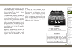
Push the liftgate button on the key fob twice
within five seconds to open the power lift-
gate. Once the liftgate is open, pushing the
button twice within five seconds a second
time will close the liftgate.
The power liftgate may also be opened or
closed by pushing the liftgate button located
on the instrument panel to right of the head-
light control switch assembly. If the liftgate is
fully open, the liftgate can be closed by
pushing the liftgate button located on the left
rear trim panel, near the liftgate opening. If
the liftgate is in motion, pushing the liftgate
button located on the left rear trim panel will
reverse the liftgate.
With a valid Passive Entry key fob within 5ft
(1.5m) of the liftgate, push the passive entry
button located to the left of liftgate release
handle to open the liftgate with one fluid
motion.NOTE:
If “Unlock All Doors 1st Press” is pro-
grammed in Uconnect, all doors will unlock
when you push the passive entry button on
the liftgate. If "Unlock Driver Door 1st Press"
is programmed in Uconnect, the liftgate will
unlock when you push the passive entry but-
ton on the liftgate. Refer to “Uconnect Set-
tings” in “Multimedia” in your Owner’s
Manual for further information.
WARNING!
Driving with the liftgate open can allow
poisonous exhaust gases into your vehicle.
You and your passengers could be injured
by these fumes. Keep the liftgate closed
when you are operating the vehicle.
Liftgate Entry
1 — Passive Entry Button
2 — Liftgate Release Handle
55
Page 58 of 344

Closing
There are several different ways to close the
liftgate:
• Manually by grasping the liftgate closing
handle and initiating lowering of the lift-
gate. Release the handle when the liftgate
takes over the closing effort.
• Key Fob
• Hands-Free
• Liftgate Instrument Panel Button
• Power Liftgate Button On The Pillar In The
Cargo Area
To Lock The Liftgate
With a valid Passive Entry key fob within 5 ft
(1.5 m) of the liftgate, pushing the Keyless
Enter-N-Go — Passive Entry lock/push but-
ton located to the left of the back-up camera
will lock the vehicle only.The power liftgate may be closed by pushing
the button, located in the upper left trim in
the liftgate opening. Pushing the button will
only close the liftgate. This button cannot be
used to open the liftgate.
Hands-Free Liftgate — If Equipped
To open or close the liftgate using hands-free
activation, use a straight in and out kicking
motion under the vehicle activation zone in
the general location below the rear license
plate. Do not move your foot sideways or in a
sweeping motion or the sensors may not de-
tect the motion.
Rear Power Liftgate Switch
Hands-Free Liftgate Activation Zone
GETTING TO KNOW YOUR VEHICLE
56
Page 59 of 344

NOTE:
Activation zone is the same for vehicles
equipped with and without trailer tow package.
When a valid kicking motion is completed,
the liftgate will chime, the hazard lights will
flash and the liftgate will open after approxi-
mately one second, or close after approxi-
mately three seconds. This assumes all op-
tions are enabled in the radio.
NOTE:
• Opening or closing the Hands-Free Liftgate
requires a valid Passive Entry key fob within
5 ft (1.5 m) of the door handle. If a valid
Passive Entry key fob is not within 5 ft
(1.5 m), the liftgate will not respond to any
kicks.
• The Hands-Free Liftgate feature may be
turned on or off in Uconnect Settings. Refer
to “Uconnect Settings” in “Multimedia” in
the Owner’s Manual for further information.
The Hands-Free Liftgate feature should be
turned off during Jacking, Tire Changing,
Manual Car Wash, and Vehicle Service.NOTE:
The Hands-free liftgate feature can be acti-
vated by any metallic object making a similar
in-and-out motion under the rear bumper,
such as cleaning using a metal broom.
NOTE:
• The Hands-Free Liftgate will only operate
when the transmission is in PARK.
• If anything obstructs the Hands-Free lift-
gate while it is opening or closing, the
liftgate will automatically reverse to the
closed/open position, provided it meets
sufficient resistance.
• There are pinch sensors attached to the
side of the liftgate opening. Light pressure
anywhere along these strips will cause the
liftgate to return to the open position.
• If the power liftgate encounters multiple
obstructions within the same cycle, the
system will automatically stop. If this oc-
curs, the liftgate must be operated manu-
ally.• The power liftgate will release, but not
power open, in temperatures below −12° F
(−24° C). Be sure to remove any buildup of
snow or ice from the liftgate before opening
the liftgate.
• If the liftgate is left open for an extended
period of time, the liftgate may need to be
closed manually to reset power liftgate
functionality.
WARNING!
• Driving with the liftgate open can allow
poisonous exhaust gases into your ve-
hicle. You and your passengers could be
injured by these fumes. Keep the liftgate
closed when you are operating the ve-
hicle.
• If you are required to drive with the
liftgate open, make sure that all win-
dows are closed, and the climate control
blower switch is set at high speed. Do
not use the recirculation mode.
57
Page 60 of 344

Gas props support the liftgate in the open
position. However, because the gas pressure
drops with temperature, it may be necessary
to assist the props when opening the liftgate
in cold weather.
NOTE:
Allow the power system to open the liftgate.
Manually pushing or pulling the liftgate may
activate the liftgate obstacle detection fea-
ture and stop the power operation or reverse
its direction.
WARNING!
During power operation, personal injury or
cargo damage may occur. Ensure the lift-
gate travel path is clear. Make sure the
liftgate is closed and latched before driv-
ing away.
INTERNAL EQUIPMENT
Power Outlets
Your vehicle is equipped with 12 Volt
(13 Amp) power outlets that can be used to
power cellular phones, small electronics and
other low powered electrical accessories. The
power outlets are labeled with either a “key”
or a “battery” symbol to indicate how the
outlet is powered. Power outlets labeled with
a “key” are powered when the ignition switch
is in the ON or ACC position, while the outlets
labeled with a “battery” are connected di-
rectly to the battery and powered at all times.
NOTE:
• All accessories connected to the “battery”
powered outlets should be removed or
turned off when the vehicle is not in use to
protect the battery against discharge.
CAUTION!
Power outlets are designed for accessory
plugs only. Do not insert any other object
in the power outlets as this will damage
the outlet and blow the fuse. Improper use
CAUTION!
of the power outlet can cause damage not
covered by your New Vehicle Limited War-
ranty.
The front power outlet is located inside the
storage area in front of the shifter.
In addition to the front power outlet, there is
also a power outlet located in the storage area
of the center console.
Front Power Outlet
GETTING TO KNOW YOUR VEHICLE
58
Page 61 of 344

A third fused 12 Volt power outlet is located
on the left quarter trim panel in the cargo
area. This power outlet has power available
when the ignition switch is in the ON or ACC
position.NOTE:
The rear cargo power outlet can be changed
to “battery” powered all the time. Refer to an
authorized dealer.
WARNING!
To avoid serious injury or death:
• Only devices designed for use in this
type of outlet should be inserted into any
12 Volt outlet.
• Do not touch with wet hands.
• Close the lid when not in use and while
driving the vehicle.
• If this outlet is mishandled, it may cause
an electric shock and failure.
CAUTION!
• Many accessories that can be plugged in
draw power from the vehicle's battery,
even when not in use (i.e., cellular
phones, etc.). Eventually, if plugged in
long enough, the vehicle's battery will
discharge sufficiently to degrade battery
life and/or prevent the engine from start-
ing.
CAUTION!
• Accessories that draw higher power (i.e.,
coolers, vacuum cleaners, lights, etc.)
will degrade the battery even more
quickly. Only use these intermittently
and with greater caution.
• After the use of high power draw acces-
sories, or long periods of the vehicle not
being started (with accessories still
plugged in), the vehicle must be driven a
sufficient length of time to allow the
generator to recharge the vehicle's bat-
tery.
Center Console Power Outlet
Rear Cargo Power Outlet
59
Page 62 of 344

Power Inverter — If Equipped
There is a 230 Volt, 150 Watt inverter outlet
located on the back of the center console to
convert DC current to AC current. This outlet
can power cellular phones, electronics and
other low power devices requiring power up to
150 Watts. Certain high-end game consoles
exceed this power limit, as will most power
tools.
To turn on the power inverter outlet, simply
plug in the device. The outlet automatically
turns off when the device is unplugged.The power inverter is designed with built-in
overload protection. If the power rating of
150 Watts is exceeded, the power inverter
automatically shuts down. Once the electri-
cal device has been removed from the outlet
the inverter should automatically reset. To
avoid overloading the circuit, check the
power ratings on electrical devices prior to
using the inverter.
WARNING!
To avoid serious injury or death:
• Do not insert any objects into the
receptacles.
• Do not touch with wet hands.
• Close the lid when not in use.
• If this outlet is mishandled, it may
cause an electric shock and failure.
ROOF LUGGAGE RACK — IF
EQUIPPED
The load carried on the roof, when equipped
with a luggage rack, must not exceed 150 lbs
(68 kg), and it should be uniformly distrib-
uted over the cargo area.
Crossbars should always be used whenever
cargo is placed on the roof rack. Check the
straps frequently to be sure that the load
remains securely attached.
NOTE:
Crossbars can be purchased at your autho-
rized dealer through Mopar parts.
External racks do not increase the total load
carrying capacity of the vehicle. Be sure that
the total occupant and luggage load inside
the vehicle, plus the load on the luggage
rack, do not exceed the maximum vehicle
load capacity.
Rear Center Console Power Inverter
GETTING TO KNOW YOUR VEHICLE
60
Page 63 of 344

WARNING!
Cargo must be securely tied down before
driving your vehicle. Improperly secured
loads can fly off the vehicle, particularly at
high speeds, resulting in personal injury or
property damage. Follow the roof rack cau-
tions when carrying cargo on your roof
rack.
CAUTION!
• To avoid damage to the roof rack and
vehicle, do not exceed the maximum
roof rack load capacity. Always distrib-
CAUTION!
ute heavy loads as evenly as possible
and secure the load appropriately.
• Long loads, which extend over the wind-
shield, such as wood panels or surf-
boards, should be secured to both the
front and rear of the vehicle.
• Place a blanket or other protection be-
tween the surface of the roof and the
load.
• Travel at reduced speeds and turn cor-
ners carefully when carrying large or
heavy loads on the roof rack. Wind
forces, due to natural causes or nearby
CAUTION!
truck traffic, can add sudden upward
loads. This is especially true on large flat
loads and may result in damage to the
cargo or your vehicle.
• Load should always be secured to cross
bars first, with tie down loops used as
additional securing points if needed. Tie
loops are intended as supplementary tie
down points only. Do not use ratcheting
mechanisms with the tie loops. Check
the straps frequently to be sure that the
load remains securely attached.
61
Page 64 of 344

INSTRUMENT CLUSTER
DISPLAY
Your vehicle may be equipped with an instru-
ment cluster display, which offers useful in-
formation to the driver. With the ignition in
the STOP/OFF mode, opening/closing of a
door will activate the display for viewing, and
display the total miles, or kilometers, in the
odometer. Your instrument cluster display is
designed to display important information
about your vehicle’s systems and features.
Using a driver interactive display located on
the instrument panel, your instrument clus-
ter display can show you how systems are
working and give you warnings when they
aren’t. The steering wheel mounted controls
allow you to scroll through and enter the main
menus and submenus. You can access the
specific information you want and make se-
lections and adjustments.
Instrument Cluster Display Location And
Controls
The instrument cluster display features a
driver-interactive display that is located in
the instrument cluster.
The instrument cluster display menu items
consist of the following:
• Speedometer
• Vehicle Info
• Driver Assist — If Equipped
• Fuel Economy
• Trip Info
• Stop/Start
• Audio
• Messages
• Screen Setup
• Speed WarningThe system allows the driver to select infor-
mation by pushing the following buttons
mounted on the steering wheel:
Instrument Cluster Display Control Buttons
1 — Left Arrow
Button4 — OK Button
2 — Up Arrow
Button5 — Down Arrow
Button
3 — Right Arrow
Button
GETTING TO KNOW YOUR INSTRUMENT PANEL
62