Page 472 of 526
7-55
7
Maintenance
Fuse NameSymbolFuse RatingCircuit Protected
SENSOR2S210APCB Block (A/CON Relay), E/R Junction Block (RLY.9), Purge Control Solenoid Valve,
RCV Control Solenoid Valve, Oil Control Valve #1~#2
ECU2E210AECM
ECU1E120AECM
INJECTORINJECTOR15A-
SENSOR1S115AOxygen Sensor (Up), Oxygen Sensor (Down)
IGN COILIGN COIL20AIgnition Coil #1~#4
ECU3E315AECM
A/CON10APCB Block (A/CON Relay)
ECU5E510AECM
SENSOR4S415AVacuum Pump
ABS3310AESC Control Module, Multipurpose Check Connector
TCM2T215ATCM, Transaxle Range Switch
Engine compartment fuse panel
■ Gamma 1.6 T-GDI
Page 473 of 526
7-56
Maintenance
Fuse NameSymbolFuse RatingCircuit Protected
SENSOR3S310AE/R Junction Block (RLY.7)
ECU4E415AECM
H/LAMP10APCB Block (Head Lamp(High) Relay)
HORN15APCB Block (Horn Relay)
Engine compartment fuse panel
■ Kappa 1.0 T-GDI
Fuse NameSymbolFuse RatingCircuit Protected
SENSOR2S210APCB Block (A/CON Relay), E/R Junction Block (RLY.9), RCV Control Solenoid Valve,
Purge Control Solenoid Valve, Oil Control Valve #1~#3
ECU2E210AECM
ECU1E120AECM
INJECTORINJECTOR15A-
SENSOR1S115AOxygen Sensor (Up), Oxygen Sensor (Down)
Page 474 of 526
7-57
7
Maintenance
Fuse NameSymbolFuse RatingCircuit Protected
IGN COILIGN COIL20AIgnition Coil #1~#3
ECU3E315AECM
A/CON10APCB Block (A/CON Relay)
ECU5E510AECM
SENSOR4S415A-
ABS3310AMultipurpose Check Connector, ESC Control Module
TCM2T215A-
SENSOR3S310AE/R Junction Block (RLY.7)
ECU4E415AECM
H/LAMP10APCB Block (Head Lamp (High) Relay)
HORN15APCB Block (Horn Relay)
Page 475 of 526
7-58
Maintenance
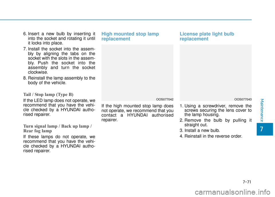
Engine compartment fuse panel(Battery terminal cover)
Inside the fuse/relay box cover, you
can find the fuse/relay label describ-
ing fuse/relay names and ratings.
Information
Not all fuse panel descriptions in this
manual may be applicable to your
vehicle; the information is accurate at
the time of printing. When you inspect
the fuse panel in your vehicle, refer to
the fuse panel label.
i
OOS077035R
OOS078107
After checking the fuse panel in the engine compartment, securely
install the cover. If it is not securely latched, electrical failure may occur
from water contact.
NOTICE
Page 488 of 526

7-71
7
Maintenance
6. Insert a new bulb by inserting itinto the socket and rotating it until
it locks into place.
7. Install the socket into the assem- bly by aligning the tabs on the
socket with the slots in the assem-
bly. Push the socket into the
assembly and turn the socket
clockwise.
8. Reinstall the lamp assembly to the body of the vehicle.
Tail / Stop lamp (Type B)
If the LED lamp does not operate, we
recommend that you have the vehi-
cle checked by a HYUNDAI autho-
rised repairer.
Turn signal lamp / Back up lamp /
Rear fog lamp
If these lamps do not operate, we
recommend that you have the vehi-
cle checked by a HYUNDAI autho-
rised repairer.
High mounted stop lamp
replacement
If the high mounted stop lamp does
not operate, we recommend that you
contact a HYUNDAI authorised
repairer.
License plate light bulb
replacement
1. Using a screwdriver, remove thescrews securing the lens cover to
the lamp housing.
2. Remove the bulb by pulling it straight out.
3. Install a new bulb.
4. Reinstall in the reverse order.
OOS077042OOS077043
Page 507 of 526

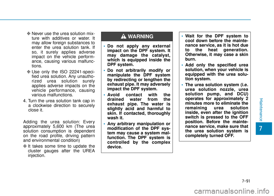
Adding the urea solution
To refill the urea solution from the
refill hose
1. Press the ignition switch to theOFF position.
2. Turn the urea solution tank cap in a counterclockwise direction to
open it.
3. Fully insert the refill hose to fully add the ISO 22241-specified urea
solution or above the mark on the
urea solution tank. ❈
Pay the great caution not to add
the urea solution into the fuel
tank. If not, it surely applies
adverse impact on the vehicle
performance, causing various
malfunctions.
❈ Never use the urea solution mix-
ture with additives or water. It
may allow foreign substances to
enter the urea solution tank. If
so, it surely applies adverse
impact on the vehicle perform-
ance, causing various malfunc-
tions.
❈ Use only the ISO 22241-speci-
fied urea solution. Any unautho-
rized urea solution surely
applies adverse impacts on the
vehicle performance, causing
various malfunctions.
4. Turn the urea solution tank cap in a clockwise direction to securely
close it.
To refill the urea solution from the
refill bottle
1. Press the ignition switch to the OFF position
2. Turn the urea solution tank cap in a counterclockwise direction to
open it.
3. Fully add the ISO 22241-specified urea solution or above the mark
on the urea solution tank.
❈ Pay the great caution not to add
the urea solution into the fuel
tank. If not, it surely applies
adverse impact on the vehicle
performance, causing various
malfunctions.
❈ Pay the great caution not to
over-fill the (completely) fulfilled
urea solution tank by force whilst
refilling the urea solution from
the refill bottle. The over-filled
urea solution tank will be
expanded when it becomes
frozen and this can cause a seri-
ous malfunction of the urea solu-
tion tank or urea solution sys-
tem.
7-90
Maintenance
OOS048415
Page 508 of 526

❈Never use the urea solution mix-
ture with additives or water. It
may allow foreign substances to
enter the urea solution tank. If
so, it surely applies adverse
impact on the vehicle perform-
ance, causing various malfunc-
tions.
❈ Use only the ISO 22241-speci-
fied urea solution. Any unautho-
rized urea solution surely
applies adverse impacts on the
vehicle performance, causing
various malfunctions.
4. Turn the urea solution tank cap in a clockwise direction to securely
close it.
Adding the urea solution: Every
approximately 5,600 km (The urea
solution consumption is dependent
on the road profile, driving pattern
and environmental condition)
❈ It takes some time to update the
cluster gauges after the UREA
injection.
7-91
7
Maintenance
Do not apply any external
impact on the DPF system. It
may damage the catalyst,
which is equipped inside the
DPF system.
Do not arbitrarily modify or
manipulate the DPF system
by redirecting or lengthen the
exhaust pipe. It may adversely
impact the DPF system.
Avoid contact with the
drained water from the
exhaust pipe. The water is
slightly acid and harmful to
skin. If contacted, thoroughly
wash it.
Any arbitrary manipulation or
modification of the DPF sys-
tem may cause a system mal-
function. The DPF system is
controlled by the complex
device.
Wait for the DPF system to
cool down before the mainte-
nance service, as it is hot due
to the heat generation.
Otherwise, it may case a skin
burn.
Add only the specified urea
solution, when your vehicle is
equipped with the urea solu-
tion system.
The urea solution system (i.e.
urea solution nozzle, urea
solution pump, and DCU)
operates for approximately 2
minutes more to eliminate the
remaining urea solution
inside, even after the ignition
switch is pressed to the OFF
position. Before the mainte-
nance service, make sure that
the urea solution system is
completely turned OFF.WARNING