Page 403 of 555
7-6
Maintenance
Owner Maintenance Schedule
When you stop for fuel:
• Check coolant level in the coolantreservoir.
Check the windshield washer fluid level.
Check for low or under-inflated tires.
While operating your vehicle:
Check for vibrations in the steeringwheel. Notice if there is any
increased steering effort or loose-
ness in the steering wheel, or
change in its straight-ahead posi-
tion.
Notice if your vehicle constantly turns slightly or "pulls" to one side
when traveling on smooth, level
road.
When stopping, listen and check for unusual sounds, pulling to one
side, increased brake pedal travel
or "hard-to-push" brake pedal.
If any slipping or changes in the operation of your reduction gear
occurs, check the reduction gear
fluid level.
Check the reduction gear P (Park) function.
Check the parking brake.
Check for fluid leaks under your vehicle (water dripping from the air
conditioning system during or after
use is normal).
At least monthly:
Check coolant level in the coolantreservoir.
Check the operation of all exterior lights, including the brake lights,
turn signals and hazard warning
flashers.
Check the inflation pressures of all tires including the spare for tires
that are worn, show uneven wear,
or are damaged.
Check for loose wheel lug nuts.
Be careful when checking your
coolant level when the parts in
the motor compartment are hot.
This may result in coolant being
blown out of the opening and
cause serious burns and other
injuries.
WARNING
Page 418 of 555
7-21
7
Maintenance
Type A
1. Raise the wiper arm and slightlyrotate the wiper blade assembly to
expose the plastic locking clip.
2. Press the clip (1) and slide theblade assembly downward (2).
3. Lift it off the arm.
4. Install the blade assembly in the reverse order of removal.
5. Return the wiper arm on the wind- shield.
Type B
1. Raise the wiper arm.
OLF074017OLMB073020
Do not allow the wiper arm to
fall against the windshield,
since it may chip or crack the
windshield.
CAUTION
OLMB073021
OLMB073022
Page 433 of 555
7-36
Maintenance
Bead
The tire bead contains steel wires
wrapped by steel cords that hold the
tire onto the rim.
Bias Ply Tire
A pneumatic tire in which the plies
are laid at alternate angles less than
90 degrees to the centerline of the
tread.
Cold Tire Pressure
The amount of air pressure in a tire,
measured in pounds per square inch
(psi) or kilopascals (kPa) before a tire
has built up heat from driving.
Curb Weight
This means the weight of a motor
vehicle with standard and optional
equipment including the maximum
capacity of fuel, oil and coolant, but
without passengers and cargo.
DOT Markings
A code molded into the sidewall of a
tire signifying that the tire is in com-
pliance with the U.S. Department of
Transportation motor vehicle safety
standards. The DOT code includes
the Tire Identification Number (TIN),
an alphanumeric designator which
can also identify the tire manufactur-
er, production plant, brand and date
of production.
GVWR
Gross Vehicle Weight Rating
GAWR FRT
Gross Axle Weight Rating for the
Front Axle.
GAWR RR
Gross Axle Weight Rating for the
Rear axle.
Intended Outboard Sidewall
The side of an asymmetrical tire, that
must always face outward when
mounted on a vehicle.
Kilopascal (kPa)
The metric unit for air pressure.
Light truck(LT) tire
A tire designated by its manufacturer
as primarily intended for use on light-
weight trucks or multipurpose pas-
senger vehicles.
Load ratings
The maximum load that a tire is rated
to carry for a given inflation pressure.
Load Index
An assigned number ranging from 1
to 279 that corresponds to the load
carrying capacity of a tire.
Page 434 of 555
7-37
7
Maintenance
Maximum Inflation Pressure
The maximum air pressure to which
a cold tire may be inflated. The max-
imum air pressure is molded onto the
sidewall.
Maximum Load Rating
The load rating for a tire at the maxi-
mum permissible inflation pressure
for that tire.
Maximum Loaded VehicleWeight
The sum of curb weight; accessory
weight; vehicle capacity weight; and
production options weight.
Normal Occupant Weight
The number of occupants a vehicle
is designed to seat multiplied by 150
pounds (68 kg).
Occupant Distribution
Designated seating positions.
Outward Facing Sidewall
An asymmetrical tire has a particular
side that faces outward when mount-
ed on a vehicle. The outward facing
sidewall bears white lettering or
bears manufacturer, brand, and/or
model name molding that is higher or
deeper than the same moldings on
the inner facing sidewall.
Passenger (P-Metric) tire
A tire used on passenger cars and
some light duty trucks and multipur-
pose vehicles.
Ply
A layer of rubber-coated parallel
cords.
Pneumatic tire
A mechanical device made of rubber,
chemicals, fabric and steel or other
materials, that, when mounted on an
automotive wheel provides the trac-
tion and contains the gas or fluid that
sustains the load.
Pneumatic options weight
The combined weight of installed
regular production options weighing
over 5 lb. (2.3 kg) in excess of the
standard items which they replace,
not previously considered in curb
weight or accessory weight, includ-
ing heavy duty breaks, ride levelers,
roof rack, heavy duty battery, and
special trim.
Recommended InflationPressure
Vehicle manufacturer's recommend-
ed tire inflation pressure as shown
on the tire placard.
Page 438 of 555
7-41
7
Maintenance
It is not easy to recognize tire
damage with your own eyes.
But if there is the slightest
hint of tire damage, have the
tire checked or replaced
because the tire damage may
cause air leakage from the
tire.
If the tire is damaged by driv-
ing on a rough road, off road,
pothole, manhole, or curb
stone, it will not be covered by
the warranty.
CAUTION
Page 439 of 555
7-42
Maintenance
F
FU
U S
SE
E S
S
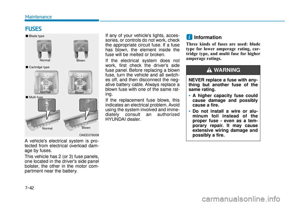
A vehicle's electrical system is pro-
tected from electrical overload dam-
age by fuses.
This vehicle has 2 (or 3) fuse panels,
one located in the driver's side panel
bolster, the other in the motor com-
partment near the battery. If any of your vehicle’s lights, acces-
sories, or controls do not work, check
the appropriate circuit fuse. If a fuse
has blown, the element inside the
fuse will be melted or broken.
If the electrical system does not
work, first check the driver's side
fuse panel. Before replacing a blown
fuse, turn the vehicle and all switch-
es off, and then disconnect the neg-
ative battery cable. Always replace a
blown fuse with one of the same rat-
ing.
If the replacement fuse blows, this
indicates an electrical problem. Avoid
using the system involved and imme-
diately consult an authorized
HYUNDAI dealer.
Information
Three kinds of fuses are used: blade
type for lower amperage rating, car-
tridge type, and multi fuse for higher
amperage ratings.
i
NEVER replace a fuse with any-
thing but another fuse of the
same rating.
A higher capacity fuse could
cause damage and possibly
cause a fire.
Do not install a wire or alu-
minum foil instead of the
proper fuse - even as a tem-
porary repair. It may cause
extensive wiring damage and
possibly a fire.
WARNING
Normal
■
Blade type
■ Cartridge type Blown
Normal Blown
OAEE076008
Normal
Blown
■ Multi fuse
Page 445 of 555
7-48
Maintenance
Fuse NameFuse RatingProtected Component
MODULE210AE/R Junction Block (Power Outlet Relay), Wireless Charger Unit, SBW Switch, BCM, USB Charging,
Smart Key Control Module, Audio, A/V & Navigation Head Unit, Power Outside Mirror Switch, AMP
PDM37.5ASmart Key Control Module
MEMORY110AAuto Light & Photo Sensor, Driver IMS Module, BCM, A/C Control Module, Instrument Cluster,
Passenger Door Module, Driver Door Module, Electro Chromic Mirror Relay Box
(Outside Mirror Folding/Unfolding Relay)
MULTIMEDIA10AA/V & Navigation Head Unit, Audio
E-SHIFTER210ASCU
IG3 310ACCM Unit
IG3 120AICM Relay Box
MDPS7.5AMDPS Unit
T/GATE10ATail Gate Relay, Main Battery Charging Switch, Quick Charging Connector Door Lock/Unlock Actuator
PDM115ASmart Key Control Module
MODULE77.5AFront Seat Warmer Control Module, Front Air Ventilation Seat Control Module, Rear Seat Warmer Module
HTD STRG15ABCM
Instrument panel fuse panel
Page 452 of 555
7-55
7
Maintenance
L
LI
IG
G H
H T
T
B
B U
U L
LB
B S
S
Consult an authorized HYUNDAI
dealer to replace most vehicle light
bulbs. It is difficult to replace vehicle
light bulbs because other parts of the
vehicle must be removed before you
can get to the bulb. This is especially
true for removing the headlamp
assembly to get to the bulb(s).
Removing/installing the headlamp
assembly can result in damage to
the vehicle.
Information
After heavy driving, rain or washing,
lamps could appear frosty. This condi-
tion is caused by the temperature dif-
ference between the lamp inside and
the outside temperature. This is simi-
lar to the condensation on your win-
dows inside your vehicle during the
rain and doesn ’t indicate a problem
with your vehicle. If the water leaks
into the lamp bulb circuitry, have your
vehicle checked by an authorized
HYUNDAI dealer.
Information
• A normally functioning lamp may flicker momentarily to stabilize the
vehicle’s electrical control system.
However, if the lamp goes out after
flickering momentarily, or contin-
ues to flicker, we recommend the
system be checked by an authorized
HYUNDAI dealer.
• The position lamp may not turn on when the position lamp switch is
turned on, but the position lamp and
headlamp switch may turn on when
the headlamp switch is turned on.
This may be caused by network fail-
ure or vehicle electrical control sys-
tem malfunction. If this occurs, we
recommend the system be checked
by an authorized HYUNDAI dealer.
i
i
Prior to replacing a lamp,
depress the foot brake, shift
to P (Park), apply the parking
brake, place the POWER but-
ton in the OFF position and
take the key with you when
leaving the vehicle to avoid
sudden movement of the vehi-
cle and to prevent possible
electric shock.
Be aware the bulbs may be
hot and may burn your fin-
gers.
WARNING