2019 FORD F650/750 Instrument
[x] Cancel search: InstrumentPage 182 of 387

Engine compartment (with engine off)
Inspect for glazing, fraying or cracking. There should be no
more than 5-7 cracks per rib, per 1 in (2.5 cm)
Belts (fan, alternator,
water pump and air
conditioning
compressor)
Inspect for signs of fluid puddles or dripping fluid on the
ground under the engine, or the underside of the engine.
Fluid leaks
Inspect for debris that may have collected on the HVAC air
inlet grille or inside the exterior module as this may reduce
system performance.
HVAC air inlet Engine starting (with parking brake applied)
Before entering the cab, verify that the vehicle is equipped
with spare electrical fuses (if used), three red reflective
triangles, a properly charged and rated fire extinguisher and
wheel chocks.
Safety and emergency
equipment
Walk around the vehicle and verify all steps and grab handles,
inside and out (as well as behind), are tight and clean. Use
extreme caution and a three-point stance at all times.
Inspect door latches for proper closing, latching and locking.
Set the parking brake. Make sure the gearshift lever is in
neutral (N) or park (P) (if equipped with a park position).
Starting the engine
Diesel engine:
Turn the key to the on position. Turn the key
to start when the wait to start indicator light in the instrument
cluster turns off.
Gasoline engine:
Turn the key to start, and then release it
as soon as the engine starts.
Verify pressure builds to normal operating range.
Engine oil pressure
A tone indicating low air pressure should sound immediately
after the engine starts but before the compressor has built-
up pressure. The tone should stop when the air pressure
reaches
70 psi (483 kPa). Let the air pressure build to
governed cutout pressure, which should occur between
115– 130 psi (793–896 kPa)
.
Low air pressure warning
tone (if equipped with an
air compressor)
Press the accelerator and verify that it operates smoothly,
without any binding or irregular feel. Release the pedal and
verify the engine returns to idle speed immediately.
Accelerator
179
F650750 (TBC) , enUSA, Edition date: 201804, Second-Printing Vehicle Inspection Guide
Page 224 of 387
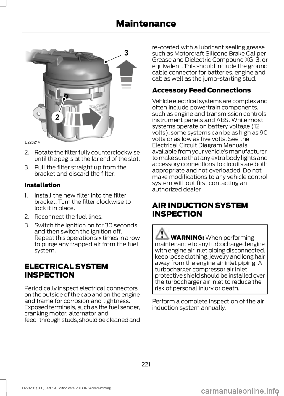
2.
Rotate the filter fully counterclockwise
until the peg is at the far end of the slot.
3. Pull the filter straight up from the bracket and discard the filter.
Installation
1. Install the new filter into the filter bracket. Turn the filter clockwise to
lock it in place.
2. Reconnect the fuel lines.
3. Switch the ignition on for 30 seconds and then switch the ignition off.
Repeat this operation six times in a row
to purge any trapped air from the fuel
system.
ELECTRICAL SYSTEM
INSPECTION
Periodically inspect electrical connectors
on the outside of the cab and on the engine
and frame for corrosion and tightness.
Exposed terminals, such as the fuel sender,
cranking motor, alternator and
feed-through studs, should be cleaned and re-coated with a lubricant sealing grease
such as Motorcraft Silicone Brake Caliper
Grease and Dielectric Compound XG-3, or
equivalent. This should include the ground
cable connector for batteries, engine and
cab as well as the jump-starting stud.
Accessory Feed Connections
Vehicle electrical systems are complex and
often include powertrain components,
such as engine and transmission controls,
instrument panels and ABS. While most
systems operate on battery voltage (12
volts), some systems can be as high as 90
volts or as low as five volts. See the
Electrical Circuit Diagram Manuals,
available from your vehicle
’s manufacturer,
to make sure that any extra body lights and
accessory connections to circuits are both
appropriate and not overloaded. Do not
make modifications to any vehicle control
system without first contacting an
authorized dealer.
AIR INDUCTION SYSTEM
INSPECTION WARNING: When performing
maintenance to any turbocharged engine
with engine air inlet piping disconnected,
keep loose clothing, jewelry and long hair
away from the engine air inlet piping. A
turbocharger compressor air inlet
protective shield should be installed over
the turbocharger air inlet to reduce the
risk of personal injury or death.
Perform a complete inspection of the air
induction system annually.
221
F650750 (TBC) , enUSA, Edition date: 201804, Second-Printing MaintenanceE226214
2
3
Page 235 of 387
To clean the windshield and wiper blades:
•
Clean the windshield with a
non-abrasive glass cleaner. When
cleaning the interior of the windshield,
avoid getting any glass cleaner on the
instrument panel or door panels. Wipe
any glass cleaner off these surfaces
immediately.
• For windshields contaminated with
tree sap, chemicals, wax or bugs, clean
the entire windshield using steel wool
(no greater than 0000 grade) in a
circular motion and rinse with water.
• Clean the wiper blades with isopropyl
rubbing alcohol or windshield washer
concentrate.
Note: Do not use razor blades or other
sharp objects to clean or remove decals
from the inside of the heated rear window.
The vehicle warranty does not cover
damage caused to the heated rear window
grid lines.
CLEANING THE INTERIOR WARNING: Do not use cleaning
solvents, bleach or dye on the vehicle's
seatbelts, as these actions may weaken
the belt webbing. WARNING:
On vehicles equipped
with seat-mounted airbags, do not use
chemical solvents or strong detergents.
Such products could contaminate the
side airbag system and affect
performance of the side airbag in a crash. For fabric, carpets, cloth seats and seats
equipped with side airbags:
•
Remove dust and loose dirt with a
vacuum cleaner.
• Remove light stains and soil with
Motorcraft Professional Strength
Carpet & Upholstery Cleaner.
• If grease or tar is present on the
material, spot-clean the area first with
Motorcraft Spot and Stain Remover. In
Canada, use Motorcraft Multi-Purpose
Cleaner.
• If a ring forms on the fabric after spot
cleaning, clean the entire area
immediately (but do not oversaturate)
or the ring will set.
• Do not use household cleaning
products or glass cleaners, which can
stain and discolor the fabric and affect
the flame retardant abilities of the seat
materials.
Mirrors
Do not clean the housing or glass of any
mirror with harsh abrasives, fuel or other
petroleum or ammonia-based cleaning
products.
CLEANING THE INSTRUMENT
PANEL AND INSTRUMENT
CLUSTER LENS WARNING:
Do not use chemical
solvents or strong detergents when
cleaning the steering wheel or
instrument panel to avoid contamination
of the airbag system.
Note: Follow the same procedure as
cleaning leather seats for cleaning leather
instrument panels and leather interior trim
surfaces.
232
F650750 (TBC) , enUSA, Edition date: 201804, Second-Printing Vehicle Care
Page 236 of 387
Clean the instrument panel and cluster
lens with a clean, damp and soft cloth,
then use a clean, dry and soft cloth to dry
these areas.
•
Avoid cleaners or polishes that increase
the gloss of the upper portion of the
instrument panel. The dull finish in this
area helps protect you from
undesirable windshield reflection.
• Do not use any household cleaning
products or glass cleaners as these
may damage the finish of the
instrument panel, interior trim and
cluster lens.
• Wash or wipe your hands clean if you
have been in contact with certain
products such as insect repellent and
suntan lotion to avoid possible damage
to the interior painted surfaces.
• Do not allow air fresheners and hand
sanitizers to spill onto interior surfaces.
If a spill occurs, wipe off immediately.
Your warranty may not cover these
damages.
If a staining liquid like coffee or juice has
been spilled on the instrument panel or on
interior trim surfaces:
1. Wipe up spilled liquid using a clean, soft cloth as quickly as possible.
2. Use Motorcraft Premium Leather and Vinyl Cleaner or a commercially
available leather cleaning product for
automotive interiors. Test any cleaner
or stain remover on an inconspicuous
area.
3. Alternatively, wipe the surface with a clean, soft cloth and a mild soap and
water solution. Dry the area with a
clean, soft cloth.
4. If necessary, apply more soap and water solution or cleaning product to
a clean, soft cloth and press it onto the
soiled area. Allow this to set at room
temperature for 30 minutes. 5. Remove the soaked cloth, then with a
clean, damp cloth, use a rubbing
motion for 60 seconds on the soiled
area.
6. Dry the area with a clean, soft cloth.
REPAIRING MINOR PAINT
DAMAGE
Authorized dealers have touch-up paint to
match your vehicle ’s color. Your vehicle
color code is printed on a sticker on the
front, left-hand side door jamb. Take your
color code to your authorized dealer to
make sure you get the correct color.
Before repairing minor paint damage, use
a cleaner such as Motorcraft Bug and Tar
Remover to remove particles such as bird
droppings, tree sap, insect deposits, tar
spots, road salt and industrial fallout.
Always read the instructions before using
cleaning products.
CLEANING THE WHEELS (IF
EQUIPPED)
1. Regularly clean them with a wheel cleaner. We recommend that you use
Ford approved wheel cleaner if
available.
2. Remove dirt and brake dust with a sponge.
3. Remove tar and grease with a bug and
tar remover. We recommend that you
use Ford approved bug and tar remover
if available.
4. Thoroughly rinse the wheels with water
after cleaning.
233
F650750 (TBC) , enUSA, Edition date: 201804, Second-Printing Vehicle Care
Page 262 of 387
VEHICLE IDENTIFICATION
NUMBER
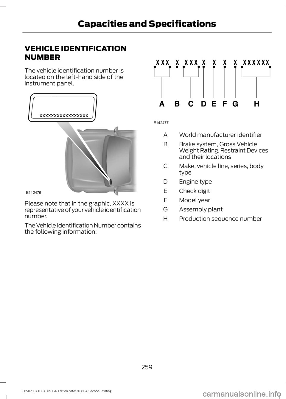
The vehicle identification number is
located on the left-hand side of the
instrument panel.
Please note that in the graphic, XXXX is
representative of your vehicle identification
number.
The Vehicle Identification Number contains
the following information: World manufacturer identifier
A
Brake system, Gross Vehicle
Weight Rating, Restraint Devices
and their locations
B
Make, vehicle line, series, body
type
C
Engine type
D
Check digit
E
Model year
F
Assembly plant
G
Production sequence number
H
259
F650750 (TBC) , enUSA, Edition date: 201804, Second-Printing Capacities and SpecificationsE142476 E142477
Page 279 of 387
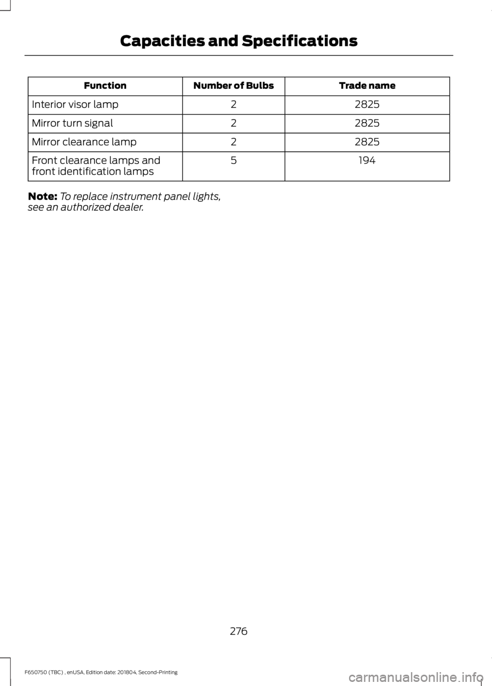
Trade name
Number of Bulbs
Function
2825
2
Interior visor lamp
2825
2
Mirror turn signal
2825
2
Mirror clearance lamp
194
5
Front clearance lamps and
front identification lamps
Note: To replace instrument panel lights,
see an authorized dealer.
276
F650750 (TBC) , enUSA, Edition date: 201804, Second-Printing Capacities and Specifications
Page 289 of 387
primary responsibility is the safe
operation of your vehicle. We
recommend against the use of any
hand-held device while driving and
encourage the use of voice-operated
systems when possible. Make sure you
are aware of all applicable local laws
that may affect the use of electronic
devices while driving.
The media hub may be on the instrument
panel or center console.
The media hub may contain one or more
of the following inputs:
See USB Port (page 285).
See
Audio Input Jack (page 284).
286
F650750 (TBC) , enUSA, Edition date: 201804, Second-Printing Audio System
Page 321 of 387
AUXILIARY SWITCHES
For maximum vehicle performance, keep
the following information in mind when
adding accessories or equipment to your
vehicle:
•
When adding accessories, equipment,
passengers and luggage to your
vehicle, do not exceed the total weight
capacity of the vehicle or of the front
or rear axle (GVWR or GAWR as
indicated on the Safety Compliance
Certification label). Ask an authorized
dealer for specific weight information.
• The Federal Communications
Commission (FCC) and Canadian
Radio Telecommunications
Commission (CRTC) regulate the use
of mobile communications systems
equipped with radio transmitters, for
example, two-way radios, telephones
and theft alarms. Any such equipment
installed in your vehicle should comply
with Federal Communications
Commission (FCC) and Canadian
Radio Telecommunications
Commission (CRTC) regulations, and
should be installed by an authorized
dealer.
• An authorized dealer needs to install
mobile communications systems.
Improper installation may harm the
operation of your vehicle, particularly
if the manufacturer did not design the
mobile communication system
specifically for automotive use.
• If you or an authorized Ford dealer add
any non-Ford electrical or electronic
accessories or components to your
vehicle, you may adversely affect
battery performance and durability. In
addition, you may also adversely affect
the performance of other electrical
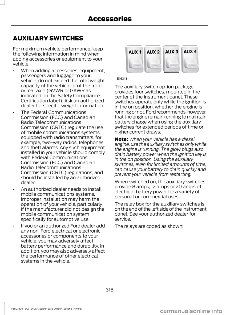
systems in the vehicle. The auxiliary switch option package
provides four switches, mounted in the
center of the instrument panel. These
switches operate only while the ignition is
in the on position, whether the engine is
running or not. Ford recommends, however,
that the engine remain running to maintain
battery charge when using the auxiliary
switches for extended periods of time or
higher current draws.
Note:
When your vehicle has a diesel
engine, use the auxiliary switches only while
the engine is running. The glow plugs also
drain battery power when the ignition key is
in the on position. Using the auxiliary
switches, even for limited amounts of time,
can cause your battery to drain quickly and
prevent your vehicle from restarting.
When switched on, the auxiliary switches
provide 8 amps, 12 amps or 20 amps of
electrical battery power for a variety of
personal or commercial uses.
The relay box for the auxiliary switches is
on the end of the left side of the instrument
panel. See your authorized dealer for
service.
The relays are coded as shown:
318
F650750 (TBC) , enUSA, Edition date: 201804, Second-Printing AccessoriesE163431