2019 FORD F650/750 Instrument
[x] Cancel search: InstrumentPage 126 of 387
If the system is disabled, normal
braking is still effective. If the
brake warning lamp illuminates
when you release the parking brake, have
the system checked by an authorized
dealer. It also illuminates momentarily
when you switch the ignition on to confirm
the lamp is functional. If it does not
illuminate when you switch the ignition on,
or begins to flash at any time, have the
system checked by an authorized dealer.
HINTS ON DRIVING WITH
ANTI-LOCK BRAKES
The anti-lock braking system does not
eliminate the risks when:
• You drive too closely to the vehicle in
front of you.
• Your vehicle is hydroplaning.
• You take corners too fast.
• The road surface is poor.
Note: If the system activates, the brake
pedal may pulse and may travel further.
Maintain pressure on the brake pedal. You
may also hear a noise from the system. This
is normal.
PARKING BRAKE
Hydraulic Brakes (If Equipped) WARNING:
Always set the parking
brake and leave your vehicle with the
transmission in park (P). WARNING:
This control is for
parking only. Do not leave the vehicle
unattended after setting the parking
brake without placing the transmission
in park (P). We recommend using wheel
chocks for hilly or off-road
circumstances. WARNING:
Unexpected and
possibly sudden vehicle movement may
occur if you do not take these
precautions. WARNING:
If the parking brake is
fully released, but the brake warning
lamp remains illuminated, the brakes
may not be working properly. Have your
vehicle checked as soon as possible.
Apply the parking brake whenever the
vehicle is parked. To set the parking brake,
pull the handle up until it snaps into the
locked position.
When the parking brake is out of
adjustment, seek service immediately. The parking brake warning lamp
in the instrument cluster
illuminates, and remains
illuminated (when you switch on the
ignition), until you release the parking
brake. 123
F650750 (TBC) , enUSA, Edition date: 201804, Second-Printing BrakesE209041 E208810 E210347
Page 131 of 387
Note:
Engine speed has a major influence
on limiting performance. When engine
speed stays at the maximum allowable
level, the exhaust brake operates at peak
performance.
Note: Exhaust brakes operate effectively
with automatic transmissions. However,
performance varies with engine speed and
the gear selected by the transmission.
An exhaust brake is an auxiliary braking
system that assists, but does not replace,
the primary brake system. It helps control
vehicle speed. It is not a vehicle-stopping
device.
Use the button on the instrument panel, in
combination with the accelerator pedal,
to maximize the use of the exhaust brake
in the following conditions:
• Off-highway driving.
• Mountain driving.
• Heavy traffic.
• High-speed highway driving. To switch the exhaust brake on, press the
button. A light on the instrument cluster
indicates the system is on. Press the button
again to switch it off.
While approaching a steep grade, make
sure that the exhaust brake switch is on.
The exhaust brake begins working as soon
as you remove your foot from the
accelerator pedal.
Before descending a hill or steep grade,
always select the proper gear. If you take
the transmission out of gear while
descending, you may not be able to select
another gear because of maximum
governed RPM.
Make sure the engine speed does not
exceed the maximum allowable engine
RPM. Exceeding the maximum allowable
engine RPM can result in damage to the
engine. Apply the service brakes to reduce
the engine RPM or make a slower descent
by using a lower gear.
While driving down a grade, use a low
enough gear to descend safely with a
minimum application of the service brakes.
As a general guideline, use the same gear
as you use to ascend the hill.
Exhaust Brake Operating
Characteristics
The exhaust brake switches on when you
remove your feet from the accelerator
pedal and the exhaust brake is on.
If the brake is working properly, there will
be:
•
A slight change in engine sound when
the exhaust brake turns on.
• A smooth braking effect. Do not expect
a retarding effect similar to sudden,
hard application of the service brakes.
128
F650750 (TBC) , enUSA, Edition date: 201804, Second-Printing BrakesE215226
Page 132 of 387
•
A retarding force possibly felt acting
against your body during brake
application (depending on the grade
and vehicle load). This force prevents
the vehicle from going much faster.
• Engine temperatures remaining in the
normal operating range.
• A drop in engine RPM (depending on
grade and vehicle load) during a
descent.
• A decrease in road speed when
applying the exhaust brake during a
descent, except when your vehicle is
carrying a heavy load or the grade is
extremely steep. In these instances,
you may need to apply the service
brakes occasionally.
TRAILER BRAKES (IF EQUIPPED)
Trailer Brake Hand Control (If Equipped) WARNING:
The hand control
should never be used to apply the brakes
when the tractor and trailer are parked
unattended. Air may leak from the
system and the vehicle could possibly
move, resulting in possible property
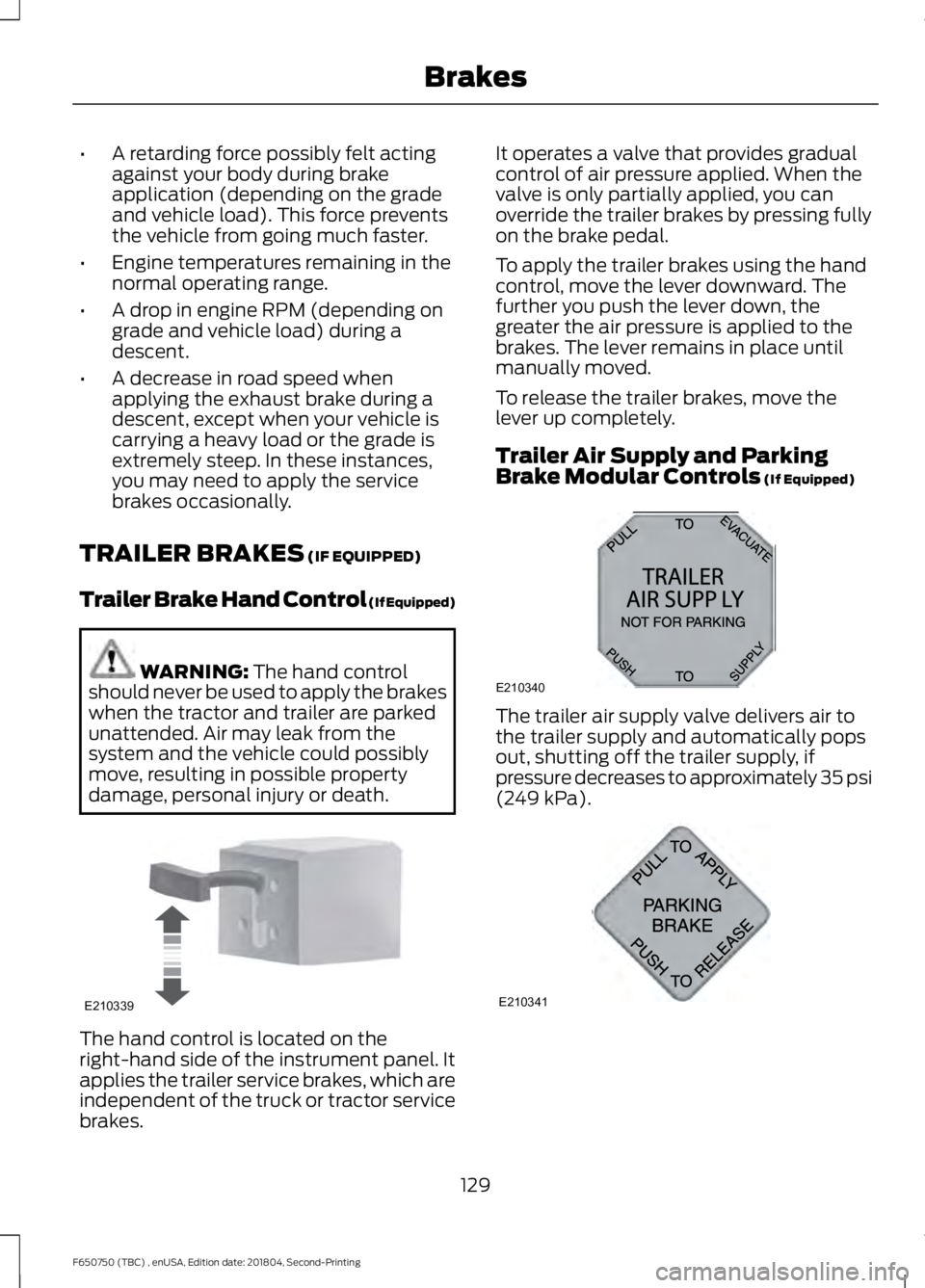
damage, personal injury or death. The hand control is located on the
right-hand side of the instrument panel. It
applies the trailer service brakes, which are
independent of the truck or tractor service
brakes. It operates a valve that provides gradual
control of air pressure applied. When the
valve is only partially applied, you can
override the trailer brakes by pressing fully
on the brake pedal.
To apply the trailer brakes using the hand
control, move the lever downward. The
further you push the lever down, the
greater the air pressure is applied to the
brakes. The lever remains in place until
manually moved.
To release the trailer brakes, move the
lever up completely.
Trailer Air Supply and Parking
Brake Modular Controls
(If Equipped)
The trailer air supply valve delivers air to
the trailer supply and automatically pops
out, shutting off the trailer supply, if
pressure decreases to approximately 35 psi
(249 kPa)
.
129
F650750 (TBC) , enUSA, Edition date: 201804, Second-Printing BrakesE210339 E210340
A
B
12
A320
A E210341
Page 136 of 387
PRINCIPLE OF OPERATION
The traction control system helps avoid
drive wheel spin and loss of traction.
If your vehicle begins to slide, the system
applies the brakes to individual wheels
and, when needed, reduces engine power
at the same time. If the wheels spin when
accelerating on slippery or loose surfaces,
the system reduces engine power in order
to increase traction.
Note:
The system does not apply the brakes
when vehicle speed is above 25 mph
(40 km/h).
USING TRACTION CONTROL -
VEHICLES WITH: AIR BRAKES WARNING:
The stability and
traction control light illuminates steadily
if the system detects a failure. Make sure
you did not manually disable the traction
control system using the information
display controls or the switch. If the
stability control and traction control light
is still illuminating steadily, have the
system serviced by an authorized dealer
immediately. Operating your vehicle with
the traction control disabled could lead
to an increased risk of loss of vehicle
control, vehicle rollover, personal injury
and death.
Press the TCS Off button to enable the
mud/snow mode.
This is beneficial when your vehicle is stuck
in snow or on a slippery road surface. This
mode allows wheel spin to dig your vehicle
out and allows you to rock your vehicle.
Press the switch again to select standard
traction control. The system automatically
selects standard traction control at the
next ignition cycle. System Indicator Light
Note:
If the traction control light does not
flash during a traction control event or stays
illuminated, the system is not functioning
properly. Take your vehicle to an authorized
dealer for service.
During traction control operation, the
traction control light flashes rapidly and
the engine does not rev-up when you press
further on the accelerator. This is normal
and is no reason for concern.
In Mud/Snow mode, the TCS OFF light
illuminates on the instrument cluster. If a
traction event occurs in either mode, the
Stability Control and Traction Control light
flashes rapidly.
USING TRACTION CONTROL -
VEHICLES WITH: HYDRAULIC
BRAKES WARNING:
Aggressive driving in
any road conditions can cause you to
lose control of your vehicle increasing
the risk of severe personal injury or
property damage. The occurrence of a
traction control event is an indication
that at least some of the tires have
exceeded their ability to grip the road;
this may lead to an increased risk of loss
of vehicle control, vehicle rollover,
personal injury and death. If you
experience a severe road event, SLOW
DOWN.
The system automatically turns on each
time you switch the ignition on.
Use the traction control switch on the
instrument panel to switch the system off
or on.
133
F650750 (TBC) , enUSA, Edition date: 201804, Second-Printing Traction Control
(If Equipped)
Page 141 of 387
PRINCIPLE OF OPERATION
Cruise control lets you maintain a set
speed without keeping your foot on the
accelerator pedal. You can use cruise
control when your vehicle speed is greater
than 20 mph (30 km/h).
USING CRUISE CONTROL WARNING:
Do not use cruise
control on winding roads, in heavy traffic
or when the road surface is slippery. This
could result in loss of vehicle control,
serious injury or death. WARNING:
When you are going
downhill, your vehicle speed could
increase above the set speed. The
system does not apply the brakes.
To help the system to maintain the set
speed when going downhill, downshift to
a lower gear.
Your vehicle speed could decrease below
the set speed when driving uphill.
Note: The system cancels if your vehicle
speed drops below 10 mph (16 km/h) under
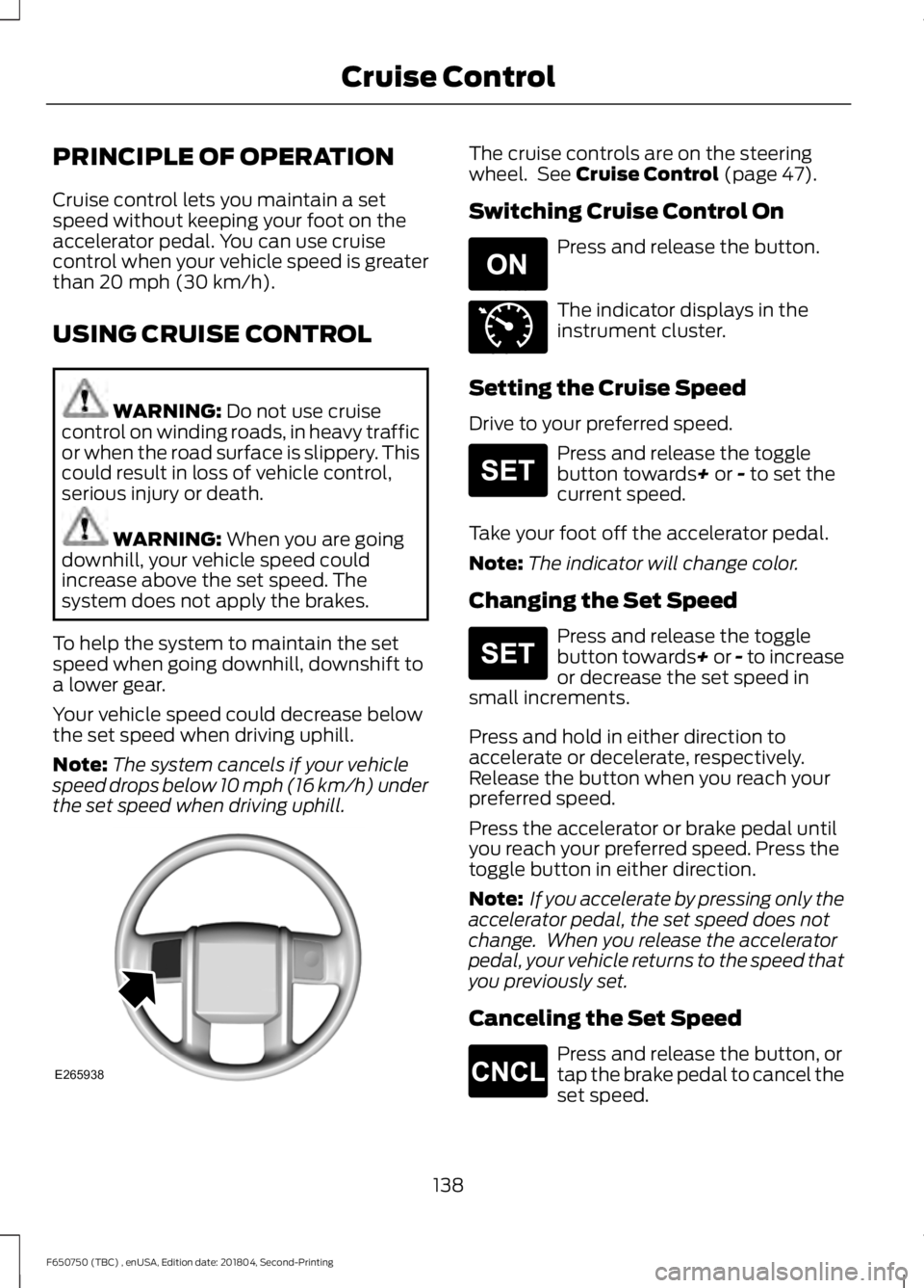
the set speed when driving uphill. The cruise controls are on the steering
wheel. See
Cruise Control (page 47).
Switching Cruise Control On Press and release the button.
The indicator displays in the
instrument cluster.
Setting the Cruise Speed
Drive to your preferred speed. Press and release the toggle
button towards
+ or - to set the
current speed.
Take your foot off the accelerator pedal.
Note: The indicator will change color.
Changing the Set Speed Press and release the toggle
button towards+ or - to increase
or decrease the set speed in
small increments.
Press and hold in either direction to
accelerate or decelerate, respectively.
Release the button when you reach your
preferred speed.
Press the accelerator or brake pedal until
you reach your preferred speed. Press the
toggle button in either direction.
Note: If you accelerate by pressing only the
accelerator pedal, the set speed does not
change. When you release the accelerator
pedal, your vehicle returns to the speed that
you previously set.
Canceling the Set Speed Press and release the button, or
tap the brake pedal to cancel the
set speed.
138
F650750 (TBC) , enUSA, Edition date: 201804, Second-Printing Cruise ControlE265938 E265296 E71340 E265306 E265306 E265298
Page 145 of 387
AIR SUSPENSION (IF EQUIPPED)
Note: Do not operate your vehicle without
air in the suspension springs. Operating your
vehicle without air in the suspension springs
damages the suspension, degrades ride
performance and may cause property
damage.
The air suspension system automatically
adjusts to different loads to maintain a
constant frame height, allows for ease of
vehicle loading, provides improved vehicle
ride, and increased driver comfort.
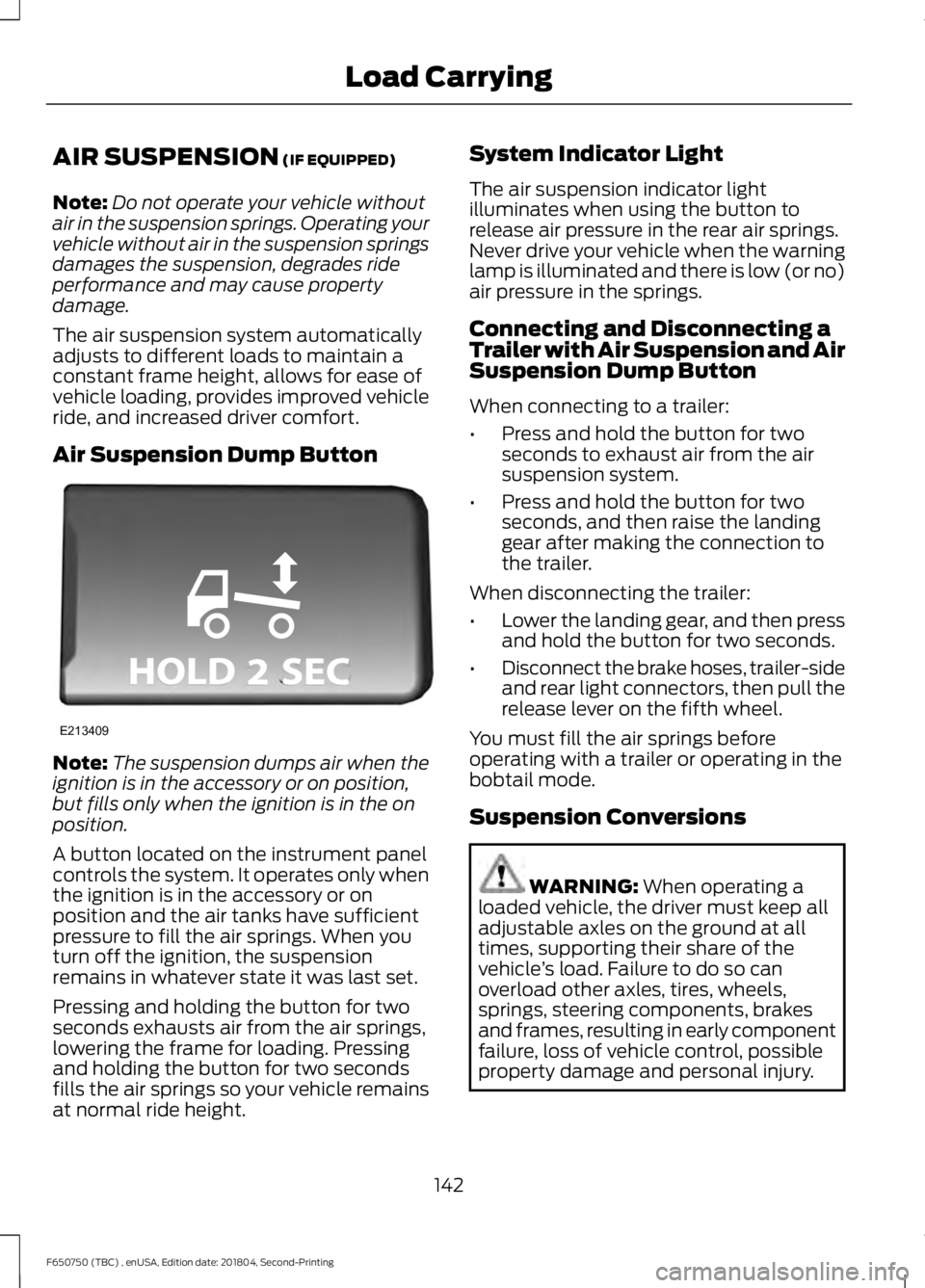
Air Suspension Dump Button Note:
The suspension dumps air when the
ignition is in the accessory or on position,
but fills only when the ignition is in the on
position.
A button located on the instrument panel
controls the system. It operates only when
the ignition is in the accessory or on
position and the air tanks have sufficient
pressure to fill the air springs. When you
turn off the ignition, the suspension
remains in whatever state it was last set.
Pressing and holding the button for two
seconds exhausts air from the air springs,
lowering the frame for loading. Pressing
and holding the button for two seconds
fills the air springs so your vehicle remains
at normal ride height. System Indicator Light
The air suspension indicator light
illuminates when using the button to
release air pressure in the rear air springs.
Never drive your vehicle when the warning
lamp is illuminated and there is low (or no)
air pressure in the springs.
Connecting and Disconnecting a
Trailer with Air Suspension and Air
Suspension Dump Button
When connecting to a trailer:
•
Press and hold the button for two
seconds to exhaust air from the air
suspension system.
• Press and hold the button for two
seconds, and then raise the landing
gear after making the connection to
the trailer.
When disconnecting the trailer:
• Lower the landing gear, and then press
and hold the button for two seconds.
• Disconnect the brake hoses, trailer-side
and rear light connectors, then pull the
release lever on the fifth wheel.
You must fill the air springs before
operating with a trailer or operating in the
bobtail mode.
Suspension Conversions WARNING:
When operating a
loaded vehicle, the driver must keep all
adjustable axles on the ground at all
times, supporting their share of the
vehicle ’s load. Failure to do so can
overload other axles, tires, wheels,
springs, steering components, brakes
and frames, resulting in early component
failure, loss of vehicle control, possible
property damage and personal injury.
142
F650750 (TBC) , enUSA, Edition date: 201804, Second-Printing Load CarryingE213409
Page 175 of 387

Protected Component
Fuse Rating
Fuse or Relay
Number
Not used.
—
98
Instrument panel 110 volt power inverter.
40A 1
99
Trailer tow turn lamp relays.
30A 1
100
Starter.
Relay
101
Trailer tow battery charge relay (U-Haul).
Relay
102
Trailer tow battery feed (air brakes).
Trailer tow right hand side turn and stop
lamps.
Relay
103
Trailer tow left hand side turn and stop
lamps.
Relay
104
Not used.
—
105
Trailer tow backup lamps.
Relay
106
Passenger air ride seat compressor.
Relay
107
1 J-case fuse.
2 Mini fuse.
Passenger Compartment Fuse
Panel
The fuse panel is in the passenger footwell.
Remove the panel cover to access the
fuses. Pull the fuse panel cover toward you to
remove it. When the clips of the panel
disengage, let the panel fall easily.
Use the provided fuse puller tool to remove
a fuse. It is on the fuse panel cover.
172
F650750 (TBC) , enUSA, Edition date: 201804, Second-Printing Fuses
Page 177 of 387
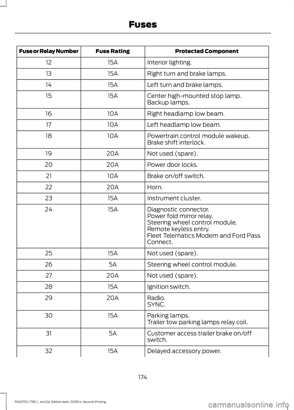
Protected Component
Fuse Rating
Fuse or Relay Number
Interior lighting.
15A
12
Right turn and brake lamps.
15A
13
Left turn and brake lamps.
15A
14
Center high-mounted stop lamp.
15A
15
Backup lamps.
Right headlamp low beam.
10A
16
Left headlamp low beam.
10A
17
Powertrain control module wakeup.
10A
18
Brake shift interlock.
Not used (spare).
20A
19
Power door locks.
20A
20
Brake on/off switch.
10A
21
Horn.
20A
22
Instrument cluster.
15A
23
Diagnostic connector.
15A
24
Power fold mirror relay.
Steering wheel control module.
Remote keyless entry.
Fleet Telematics Modem and Ford Pass
Connect.
Not used (spare).
15A
25
Steering wheel control module.
5A
26
Not used (spare).
20A
27
Ignition switch.
15A
28
Radio.
20A
29
SYNC.
Parking lamps.
15A
30
Trailer tow parking lamps relay coil.
Customer access trailer brake on/off
switch.
5A
31
Delayed accessory power.
15A
32
174
F650750 (TBC) , enUSA, Edition date: 201804, Second-Printing Fuses