Page 161 of 490
WARNING!(Continued)
•The capabilities of an ABS equipped vehicle must
never be exploited in a reckless or dangerous manner
that could jeopardize the user ’s safety or the safety of
others.
ABS is designed to function with the OEM tires. Modifica-
tion may result in degraded ABS performance.
Anti-Lock Brake Warning Light
The yellow “Anti-Lock Brake Warning Light” will turn on
when the ignition is turned to the ON/RUN mode and
may stay on for as long as four seconds.
If the “Anti-Lock Brake Warning Light” remains on or
comes on while driving, it indicates that the anti-lock
portion of the brake system is not functioning and that
service is required. However, the conventional brake sys-
tem will continue to operate normally if the “Anti-Lock
Brake Warning Light” is on.
If the “Anti-Lock Brake Warning Light” is on, the brake
system should be serviced as soon as possible to restore the
benefits of anti-lock brakes. If the “Anti-Lock Brake Warning
Light” does not come on when the ignition is turned to the
ON/RUN mode, have the light repaired as soon as possible.
Electronic Brake Control System
Your vehicle is equipped with an advanced Electronic
Brake Control system (EBC). This system includes Elec-
tronic Brake Force Distribution (EBD), Anti-Lock Brake
System (ABS), Brake Assist System (BAS), Hill Start Assist
(HSA), Traction Control System (TCS), Electronic Stability
Control (ESC), and Electronic Roll Mitigation (ERM). These
systems work together to enhance both vehicle stability
and control in various driving conditions.
Your vehicle may also be equipped with Trailer Sway
Control (TSC).
Electronic Brake Force Distribution (EBD)
This function manages the distribution of the braking
torque between the front and rear axles by limiting braking
pressure to the rear axle. This is done to prevent overslip of
the rear wheels to avoid vehicle instability, and to prevent
the rear axle from entering ABS before the front axle.
Brake System Warning Light
The red “Brake System Warning Light” will turn on when
the ignition is turned to the ON/RUN mode and may stay
on for as long as four seconds.
5
SAFETY 159
Page 162 of 490
If the “Brake System Warning Light” remains on or comes
on while driving, it indicates that the brake system is not
functioning properly and that immediate service is re-
quired. If the “Brake System Warning Light” does not come
on when the ignition is turned to the ON/RUN mode, have
the light repaired as soon as possible.
Brake Assist System (BAS)
The BAS is designed to optimize the vehicle’s braking
capability during emergency braking maneuvers. The sys-
tem detects an emergency braking situation by sensing the
rate and amount of brake application and then applies
optimum pressure to the brakes. This can help reduce
braking distances. The BAS complements the anti-lock
brake system (ABS). Applying the brakes very quickly
results in the best BAS assistance. To receive the benefit of
the system, you must apply continuous braking pressure
during the stopping sequence, (do not “pump” the brakes).
Do not reduce brake pedal pressure unless braking is no
longer desired. Once the brake pedal is released, the BAS is
deactivated.
WARNING!
The Brake Assist System (BAS) cannot prevent the
natural laws of physics from acting on the vehicle, nor
can it increase the traction afforded by prevailing road
conditions. BAS cannot prevent collisions, including
those resulting from excessive speed in turns, driving
on very slippery surfaces, or hydroplaning. The capa-
bilities of a BAS-equipped vehicle must never be
exploited in a reckless or dangerous manner, which
could jeopardize the user’s safety or the safety of
others.
Hill Start Assist (HSA)
The HSA system is designed to mitigate roll back from a
complete stop while on an incline. If the driver releases the
brake while stopped on an incline, HSA will continue to
hold the brake pressure for a short period. If the driver
does not apply the throttle before this time expires, the
system will release brake pressure and the vehicle will roll
down the hill as normal.
160 SAFETY
Page 203 of 490
Seat belts are necessary for your protection in all collisions,
and also are needed to help keep you in position, away
from an inflating air bag.
When the ORC detects a collision requiring the front air
bags, it signals the inflator units. A large quantity of
non-toxic gas is generated to inflate the front air bags.
The steering wheel hub trim cover and the upper passen-
ger side of the instrument panel separate and fold out of
the way as the air bags inflate to their full size. The front air
bags fully inflate in less time than it takes to blink your
eyes. The front air bags then quickly deflate while helping
to restrain the driver and front passenger.
Knee Impact Bolsters
The Knee Impact Bolsters help protect the knees of the
driver and front passenger, and position the front occu-
pants for improved interaction with the front air bags.
WARNING!
•Do not drill, cut, or tamper with the knee impact
bolsters in any way.
• Do not mount any accessories to the knee impact
bolsters such as alarm lights, stereos, citizen band
radios, etc.
Supplemental Driver Knee Air Bag
This vehicle is equipped with a Supplemental Driver Knee
Air Bag mounted in the instrument panel below the
steering column. The Supplemental Driver Knee Air Bag
provides enhanced protection during a frontal impact by
working together with the seat belts, pretensioners, and
front air bags.
Supplemental Side Air Bags
Supplemental Seat-Mounted Side Air Bags (SABs)
This vehicle is equipped with Supplemental Seat-Mounted
Side Air Bags (SABs).
Supplemental Seat-Mounted Side Air Bags (SABs) are
located in the outboard side of the front seats. The SABs are
marked with “SRS AIRBAG” or “AIRBAG” on a label or on
the seat trim on the outboard side of the seats.
5
SAFETY 201
Page 204 of 490
The SABs may help to reduce the risk of occupant injury
during certain side impacts, in addition to the injury
reduction potential provided by the seat belts and body
structure.When the SAB deploys, it opens the seam on the outboard
side of the seatback’s trim cover. The inflating SAB deploys
through the seat seam into the space between the occupant
and the door. The SAB moves at a very high speed and
with such a high force that it could injure occupants if they
are not seated properly, or if items are positioned in the
area where the SAB inflates. Children are at an even greater
risk of injury from a deploying air bag.
WARNING!
Do not use accessory seat covers or place objects
between you and the Side Air Bags; the performance
could be adversely affected and/or objects could be
pushed into you, causing serious injury.
Front Supplemental Seat-Mounted Side Air Bag
202 SAFETY
Page 291 of 490
Front Park/Turn Signal Lamps
1. Raise the hood to access the rear of the headlamphousing.
2. Twist the turn signal socket and remove from the headlamp housing, then pull the bulb out.
3.
Push the new bulb into the socket and reinstall the socket
by twisting until locked into the headlamp housing.
Fog Lamps
NOTE: Access to the fog lamp bulb is from the rear of the
fascia. On the left rear side of the fascia, remove the push
pin and lower the hinged access door on the air dam.
1. From behind the bumper fascia, or the access panel on the air dam, squeeze the two tabs on the side of the bulb
socket and pull straight out from the fog lamp.
CAUTION!
Do not touch the new bulb with your fingers. Oil
contamination will severely shorten bulb life. If the
bulb comes in contact with an oily surface, clean the
bulb with rubbing alcohol.
2. Disconnect the wire harness from the bulb. 3. Reconnect the wiring harness to the new bulb and
reinstall by inserting the new bulb straight into the fog
lamp until it locks into place.
Rear Tail, Stop, Turn Signal, Side Marker And
Backup Lamps
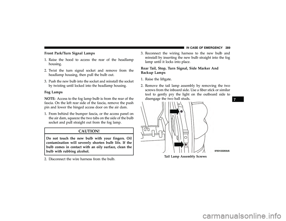
1. Raise the liftgate.
2. Remove the tail lamp assembly by removing the twoscrews from the inboard side. Use a fiber stick or similar
tool to gently pry the light on the outboard side to
disengage the two ball studs.
Tail Lamp Assembly Screws
7
IN CASE OF EMERGENCY 289
Page 304 of 490
CAUTION!
The winch mechanism is designed for use with the
winch T-handle only. Use of an air wrench or other
power tools is not recommended and can damage the
winch.
3. To remove the compact spare tire/cover assembly, as- semble the winch T-handle extensions to form a spare
tire hook, and pull the spare tire out from under the
vehicle. NOTE:
If either front tire is flat it may be necessary to jack
up the vehicle to remove the compact spare tire/cover
assembly from under the vehicle.
4. Stand the tire/cover assembly upright. Squeeze the winch retaining tabs together while simultaneously
pushing them through the hole in the cover and the steel
rim. This will free the winch cable from the spare tire.
Pulling Spare Tire
Removing Wheel Spacer
302 IN CASE OF EMERGENCY
Page 307 of 490
CAUTION!
Do not attempt to raise the vehicle by jacking on
locations other than those indicated.
Rear jack locations are between a pair of down-facing tabs
on the sill flange of the vehicle side body.
Jack LocationsJack Location
7
IN CASE OF EMERGENCY 305
Page 312 of 490
11. Stow the cable and wheel spacer before driving thevehicle. Reassemble the winch handle extensions to
form a “T” and fit the winch T-handle over the drive
nut. Rotate the nut to the right until the winch mecha-
nism clicks at least three times.
NOTE: Refer to the “Spare Tire Tools” section for instruc-
tions on assembling the T-handle.
12. Stow the jack, jack handle and winch handle tools back in the stowage compartment.
13. Check the compact spare tire pressure as soon as possible. Correct the tire pressure, as required.
Securing The Compact Spare Tire
1. Assemble the winch handle extensions to form aT-handle and fit the winch T-handle over the drive nut.
Rotate the nut to the left until the winch mechanism
stops turning freely. This will allow enough slack in the
cable to allow you to pull the wheel spacer out from
under the vehicle.
WARNING!
A loose compact spare tire/cover assembly, thrown
forward in a collision or hard stop could endanger the
occupants of the vehicle. Always stow the compact
spare tire with the cover assembly in the place pro-
vided.
CAUTION!
The winch mechanism is designed for use with the
winch T-handle only. Use of an air wrench or other
power tools is not recommended and can damage the
winch.
2. Assemble the winch handle extensions to form the spare tire hook, and pull the wheel spacer from under the
vehicle.
3. Turn the compact spare tire so that the valve stem is down, and place the tire into the compact spare tire/
cover assembly. Slide the wheel spacer through the
center of the wheel and compact spare tire/cover assem-
bly, so that the two retainer tabs snap out and engage the
compact spare tire cover on the opposite side.
310 IN CASE OF EMERGENCY