2019 DODGE GRAND CARAVAN Circuit
[x] Cancel search: CircuitPage 20 of 490

To Unlock The Doors And Liftgate
Push and release the unlock button on the key fob once to
unlock the doors. Push and release the unlock button a
second time within 5 seconds to unlock the liftgate. The
turn signal lights will flash to acknowledge the unlock
signal.
To Lock The Doors And Liftgate
Push and release the lock button on the key fob once to lock
the doors. The turn signal lights will flash to acknowledge
the lock signal.
Replacing The Battery In The Key Fob With Remote
Control
The replacement battery is one CR2032 battery.
NOTE:
•Perchlorate Material — special handling may apply. See
www.dtsc.ca.gov/hazardouswaste/perchlorate
• Do not replace coin battery unless the cluster display
indicates a message “Key Fob Low Battery”
• Do not touch the battery terminals that are on the back
housing or the printed circuit board.
1. Remove the emergency key by sliding the mechanical latch on the back of the key fob sideways with your
thumb and then pull the key out with your other hand.
Emergency Key Removal
18 GETTING TO KNOW YOUR VEHICLE
Page 121 of 490
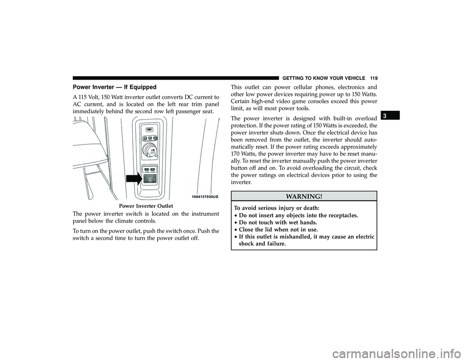
Power Inverter — If Equipped
A 115 Volt, 150 Watt inverter outlet converts DC current to
AC current, and is located on the left rear trim panel
immediately behind the second row left passenger seat.
The power inverter switch is located on the instrument
panel below the climate controls.
To turn on the power outlet, push the switch once. Push the
switch a second time to turn the power outlet off.This outlet can power cellular phones, electronics and
other low power devices requiring power up to 150 Watts.
Certain high-end video game consoles exceed this power
limit, as will most power tools.
The power inverter is designed with built-in overload
protection. If the power rating of 150 Watts is exceeded, the
power inverter shuts down. Once the electrical device has
been removed from the outlet, the inverter should auto-
matically reset. If the power rating exceeds approximately
170 Watts, the power inverter may have to be reset manu-
ally. To reset the inverter manually push the power inverter
button off and on. To avoid overloading the circuit, check
the power ratings on electrical devices prior to using the
inverter.
WARNING!
To avoid serious injury or death:
•
Do not insert any objects into the receptacles.
• Do not touch with wet hands.
• Close the lid when not in use.
• If this outlet is mishandled, it may cause an electric
shock and failure.Power Inverter Outlet
3
GETTING TO KNOW YOUR VEHICLE 119
Page 199 of 490
may result in damage to the AHRs that could impair their
function.
WARNING!
Deployed AHRs are not able to best protect you in all
types of collisions. Have deployed AHRs reset by an
authorized dealer immediately.
Supplemental Restraint Systems (SRS)
Some of the safety features described in this section may be
standard equipment on some models, or may be optional
equipment on others. If you are not sure, ask an authorized
dealer.
The air bag system must be ready to protect you in a
collision. The Occupant Restraint Controller (ORC) moni-
tors the internal circuits and interconnecting wiring asso-
ciated with the electrical Air Bag System Components.
Your vehicle may be equipped with the following Air Bag
System Components:
Air Bag System Components
•Occupant Restraint Controller (ORC)
• Air Bag Warning Light
•Steering Wheel and Column
• Instrument Panel
• Knee Impact Bolsters
• Driver and Front Passenger Air Bags
• Seat Belt Buckle Switch
• Supplemental Side Air Bags
• Supplemental Knee Air Bags
• Front and Side Impact Sensors
• Seat Belt Pretensioners
• Seat Track Position Sensors
Air Bag Warning Light
The ORC monitors the readiness of the electronic parts of
the air bag system whenever the ignition switch
is in the START or ON/RUN position. If the
ignition switch is in the OFF position or in the
ACC position, the air bag system is not on and
the air bags will not inflate.
The ORC contains a backup power supply system that may
deploy the air bag system even if the battery loses power or
it becomes disconnected prior to deployment.
5
SAFETY 197
Page 207 of 490
WARNING!
•Side Air Bags need room to inflate. Do not lean
against the door or window. Sit upright in the center
of the seat.
• Being too close to the Side Air Bags during deploy-
ment could cause you to be severely injured or
killed.
• Relying on the Side Air Bags alone could lead to
more severe injuries in a collision. The Side Air Bags
work with your seat belt to restrain you properly. In
some collisions, Side Air Bags won’t deploy at all.
Always wear your seat belt even though you have
Side Air Bags.
NOTE: Air bag covers may not be obvious in the interior
trim, but they will open during air bag deployment.
Rollover Events
Side Air Bags are designed to activate in certain rollover
events. The ORC determines whether the deployment of
the Side Air Bags in a particular rollover event is appro-
priate, based on the severity and type of collision. Vehicle
damage by itself is not a good indicator of whether or not
Side Air Bags should have deployed. The Side Air Bags will not deploy in all rollover events. The
rollover sensing system determines if a rollover event may
be in progress and whether deployment is appropriate. In
the event the vehicle experiences a rollover or near rollover
event, and deployment of the Side Air Bags is appropriate,
the rollover sensing system will also deploy the seat belt
pretensioners on both sides of the vehicle.
The SABICs may help reduce the risk of partial or complete
ejection of vehicle occupants through side windows in
certain rollover or side impact events.
Air Bag System Components
NOTE:
The Occupant Restraint Controller (ORC) monitors
the internal circuits and interconnecting wiring associated
with electrical Air Bag System Components listed below:
• Occupant Restraint Controller (ORC)
• Air Bag Warning Light
•Steering Wheel and Column
• Instrument Panel
• Knee Impact Bolsters
• Driver and Front Passenger Air Bags
• Seat Belt Buckle Switch
5
SAFETY 205
Page 292 of 490
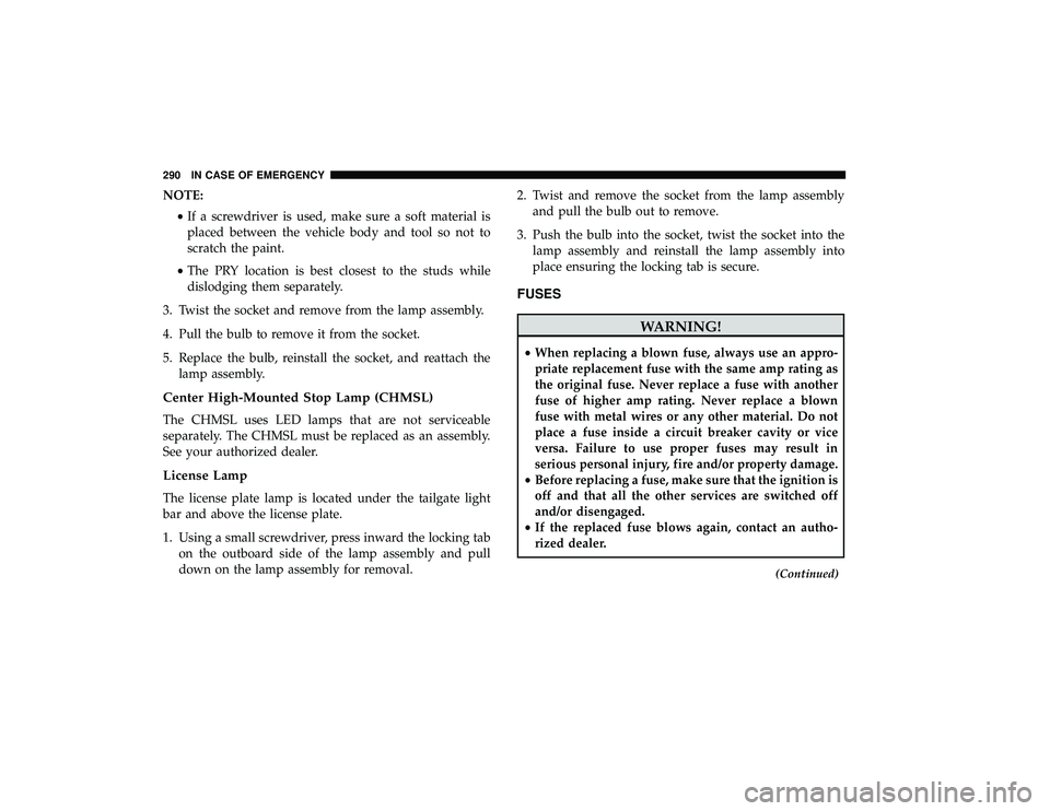
NOTE:•If a screwdriver is used, make sure a soft material is
placed between the vehicle body and tool so not to
scratch the paint.
• The PRY location is best closest to the studs while
dislodging them separately.
3. Twist the socket and remove from the lamp assembly.
4. Pull the bulb to remove it from the socket.
5. Replace the bulb, reinstall the socket, and reattach the lamp assembly.
Center High-Mounted Stop Lamp (CHMSL)
The CHMSL uses LED lamps that are not serviceable
separately. The CHMSL must be replaced as an assembly.
See your authorized dealer.
License Lamp
The license plate lamp is located under the tailgate light
bar and above the license plate.
1. Using a small screwdriver, press inward the locking tabon the outboard side of the lamp assembly and pull
down on the lamp assembly for removal. 2. Twist and remove the socket from the lamp assembly
and pull the bulb out to remove.
3. Push the bulb into the socket, twist the socket into the lamp assembly and reinstall the lamp assembly into
place ensuring the locking tab is secure.
FUSES
WARNING!
•When replacing a blown fuse, always use an appro-
priate replacement fuse with the same amp rating as
the original fuse. Never replace a fuse with another
fuse of higher amp rating. Never replace a blown
fuse with metal wires or any other material. Do not
place a fuse inside a circuit breaker cavity or vice
versa. Failure to use proper fuses may result in
serious personal injury, fire and/or property damage.
• Before replacing a fuse, make sure that the ignition is
off and that all the other services are switched off
and/or disengaged.
• If the replaced fuse blows again, contact an autho-
rized dealer.
(Continued)
290 IN CASE OF EMERGENCY
Page 294 of 490
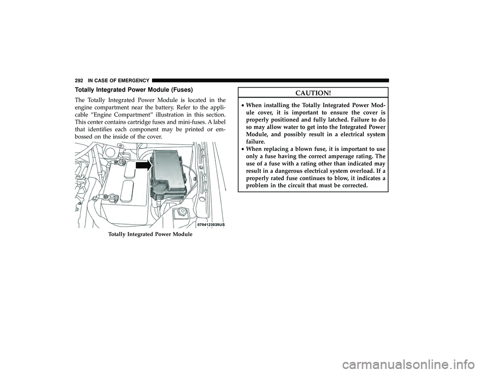
Totally Integrated Power Module (Fuses)
The Totally Integrated Power Module is located in the
engine compartment near the battery. Refer to the appli-
cable “Engine Compartment” illustration in this section.
This center contains cartridge fuses and mini-fuses. A label
that identifies each component may be printed or em-
bossed on the inside of the cover.
CAUTION!
•When installing the Totally Integrated Power Mod-
ule cover, it is important to ensure the cover is
properly positioned and fully latched. Failure to do
so may allow water to get into the Integrated Power
Module, and possibly result in a electrical system
failure.
• When replacing a blown fuse, it is important to use
only a fuse having the correct amperage rating. The
use of a fuse with a rating other than indicated may
result in a dangerous electrical system overload. If a
properly rated fuse continues to blow, it indicates a
problem in the circuit that must be corrected.
Totally Integrated Power Module
292 IN CASE OF EMERGENCY
Page 299 of 490
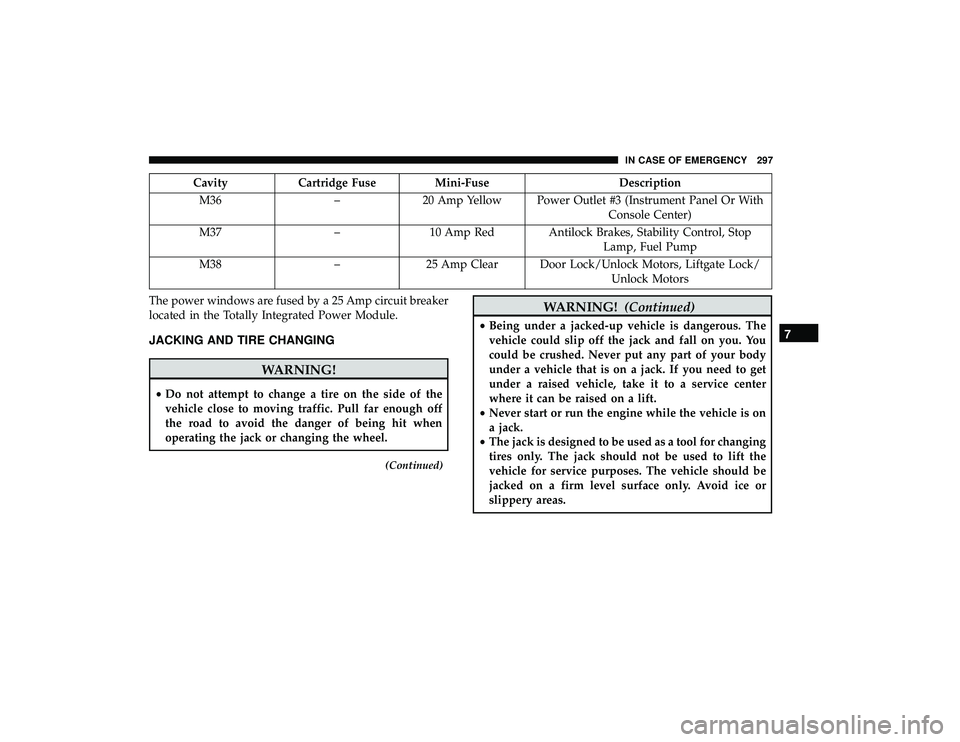
CavityCartridge Fuse Mini-Fuse Description
M36 –20 Amp Yellow Power Outlet #3 (Instrument Panel Or With
Console Center)
M37 –10 Amp Red Antilock Brakes, Stability Control, Stop
Lamp, Fuel Pump
M38 –25 Amp Clear Door Lock/Unlock Motors, Liftgate Lock/
Unlock Motors
The power windows are fused by a 25 Amp circuit breaker
located in the Totally Integrated Power Module.
JACKING AND TIRE CHANGING
WARNING!
• Do not attempt to change a tire on the side of the
vehicle close to moving traffic. Pull far enough off
the road to avoid the danger of being hit when
operating the jack or changing the wheel.
(Continued)
WARNING! (Continued)
•Being under a jacked-up vehicle is dangerous. The
vehicle could slip off the jack and fall on you. You
could be crushed. Never put any part of your body
under a vehicle that is on a jack. If you need to get
under a raised vehicle, take it to a service center
where it can be raised on a lift.
• Never start or run the engine while the vehicle is on
a jack.
• The jack is designed to be used as a tool for changing
tires only. The jack should not be used to lift the
vehicle for service purposes. The vehicle should be
jacked on a firm level surface only. Avoid ice or
slippery areas.7
IN CASE OF EMERGENCY 297