Page 65 of 130

Instrument and control functions
4-43
1
2
345
6
7
8
9
10
11
12
TIP
Although the total number of clicks
of a damping force adjusting
mechanism may not exactly match
the above specifications due to
small differences in production, the
actual number of clicks always
represents the entire adjusting
range. To obtain a precise adjust-
ment, check the number of clicks
and modify the minimum and stan-
dard specifications as necessary.
When turning the damping force
adjusting bolt in direction (a), the 0
click position and the 1 click posi-tion may be the same.
For YZF-R1M
This model is is equipped with ÖHLINS
electronic racing suspension.
The compression and rebound damp-
ing forces are electronically adjusted.
(See ERS on page 4-19.)
Spring preload
The spring preload adjustment is per-
formed manually. 1. Turn the vehicle off. 2. Slide the rubber cover back at
each coupler.
3. Remove the coupler on each front fork. NOTICE: To prevent dam-
aging the couplers, do not use
sharp tools or excessive
force.
[ECA22770]
4. To increase the spring preload and thereby harden the suspension,
turn the adjusting bolt on each fork
leg in direction (a). To decrease
the spring preload and thereby
soften the suspension, turn the ad-
justing bolt on each fork leg in di-
rection (b). 5. Attach the coupler on each fork.
6. Slide the rubber cover to the origi-
nal position.1. Rubber cover
2. Coupler
2
1
1. Spring preload adjusting boltSpring preload setting:Minimum (soft):
0 turn(s) in direction (a)*
Standard: 5 turn(s) in direction (a)*
Maximum (hard): 15 turn(s) in direction (a)*
* With the adjusting nut fully turned in
direction (b)
1
(a) (b)
BX4-9-E1_1.book 43 ページ 2018年4月27日 金曜日 午後4時3分
Page 66 of 130

Instrument and control functions
4-44
1
2
34
5
6
7
8
9
10
11
12
EAU66493
Adjusting th e shock absorber
assembly
WARNING
EWA10222
This shock absorber assembly con-
tains highly pressurized nitrogen
gas. Read and understand the fol-
lowing information before handling
the shock absorber assembly.
Do not tamper with or attempt to
open the cylinder assembly.
Do not subject the shock ab-
sorber assembly to an open
flame or other high heat source.
This may cause the unit to ex-
plode due to excessive gas
pressure.
Do not deform or damage the
cylinder in any way. Cylinder
damage will result in poor
damping performance.
Do not dispose of a damaged or
worn-out shock absorber as-
sembly yourself. Take the shock
absorber assembly to a Yamahadealer for any service.
NOTICE
ECA10102
To avoid damaging the mechanism,
do not attempt to turn beyond themaximum or minimum settings.
For YZF-R1:
This model is equipped with adjustable
suspension. The spring preload, re-
bound damping force, fast compres-
sion damping force, and slow
compression damping force can be ad-
justed.
Spring preload
1. Loosen the locknut.
2. To increase the spring preload and thereby harden the suspension,
turn the adjusting ring in direction
(a). To decrease the spring pre-
load and thereby soften the sus-
pension, turn the adjusting ring in
direction (b).
The spring preload setting is deter-
mined by measuring distance A.
The longer distance A is, the high-
er the spring preload; the shorter
distance A is, the lower the spring preload.
Use the special wrench includ-
ed in the owner’s tool kit to
make the adjustment.
1. Spring preload adjusting ring
2. Locknut
1. Distance A
(a)
(b)1
2
1
BX4-9-E1_1.book 44 ページ 2018年4月27日 金曜日 午後4時3分
Page 67 of 130

Instrument and control functions
4-45
1
2
345
6
7
8
9
10
11
12
3. Tighten the locknut to the specified
torque. NOTICE: Always tighten
the locknut against the adjust-
ing ring, and then tighten the
locknut to the specified
torque.
[ECA22760]
Rebound damping force
To increase the rebound damping force
and thereby harden the rebound damp-
ing, turn the adjusting screw in direction
(a). To decrease the rebound damping
force and thereby soften the rebound
damping, turn the adjusting screw in di-
rection (b). Compression damping force
Fast compression damping force
To increase the compression damping
force and thereby harden the fast com-
pression damping, turn the adjusting
bolt in direction (a). To decrease the
compression damping force and there-by soften the compression damping,
turn the adjusting bolt in direction (b).
Slow compression damping force
To increase the compression damping
force and thereby harden the slow
compression damping, turn the adjust-
ing screw in direction (a). To decrease
Spring preload:
Minimum (soft): Distance A = 77.5 mm (3.05 in)
Standard:
Distance A = 79.0 mm (3.11 in)
Maximum (hard): Distance A = 85.5 mm (3.37 in)
Tightening torque: Locknut: 25 N·m (2.5 kgf·m, 18 lb·ft)
1. Rebound damping force adjusting screwRebound damping setting:Minimum (soft):
23 click(s) in direction (b)*
Standard: 12 click(s) in direction (b)*
Maximum (hard): 1 click(s) in direction (b)*
* With the adjusting screw fully turned
in direction (a)(a) (b)
1
1. Fast compression damping force
adjusting boltFast compression damping settingMinimum (soft):
5.5 turn(s) in direction (b)*
Standard: 3 turn(s) in direction (b)*
Maximum (hard): 0 turn(s) in direction (b)*
* With the adjusting bolt fully turned in
direction (a)
(a) (b)
1
BX4-9-E1_1.book 45 ページ 2018年4月27日 金曜日 午後4時3分
Page 68 of 130
.
TIP
Although t")
Instrument and control functions
4-46
1
2
34
5
6
7
8
9
10
11
12 the compression damping force and
thereby soften the compression damp-
ing, turn the adjusting screw in direction
(b).
TIP
Although the total number of clicks
of a damping force adjusting
mechanism may not exactly match the above specifications due to
small differences in production, the
actual number of clicks always
represents the entire adjusting
range. To obtain a precise adjust-
ment, check the number of clicks
and modify the minimum and stan-
dard specifications as necessary.
When turning the damping force
adjusting bolt in direction (a), the 0
click position and the 1 click posi-tion may be the same.
For YZF-R1M:
This model is is equipped with ÖHLINS
electronic racing suspension.
Compression damping force and
rebound damping force
The compression and rebound damp-
ing forces are electronically controlled
and can be adjusted from the MENU
screen. See ERS on page 4-19 for in-
formation on how to adjust these set-
tings.
Spring preload
The spring preload adjustment is per- formed manually.
NOTICE
ECA10102
To avoid damaging the mechanism,
do not attempt to turn beyond themaximum or minimum settings.
1. Loosen the locknut.
2. To increase the spring preload and thereby harden the suspension,
turn the adjusting ring in direction
(a). To decrease the spring pre-
load and thereby soften the sus-
pension, turn the adjusting ring in
direction (b).
The spring preload setting is deter-
mined by measuring distance A.
The longer distance A is, the high-
er the spring preload; the shorter
distance A is, the lower the spring
preload.
Use the special wrench in the
owner’s tool kit to make the ad-
justment.
1. Slow compression damping force adjusting screwSlow compression damping settingMinimum (soft):
18 click(s) in direction (b)*
Standard: 10 click(s) in direction (b)*
Maximum (hard): 0 click(s) in direction (b)*
* With the adjusting screw fully turned
in direction (a)
(a) (b)
1
BX4-9-E1_1.book 46 ページ 2018年4月27日 金曜日 午後4時3分
Page 69 of 130
Instrument and control functions
4-47
1
2
345
6
7
8
9
10
11
12
3. Tighten the locknut to the specified
torque. NOTICE: Always tighten
the locknut against the adjust-
ing ring, and then tighten the
locknut to the specified
torque.
[ECA22760] EAU67050
EXUP systemThis model is equipped with Yamaha’s
EXUP (EXhaust Ultimate Power valve)
system. This system boosts engine
power by means of a valve that controls
exhaust flow within the exhaust cham-
ber.NOTICE
ECA15611
The EXUP system has been set and
extensively tested at the Yamaha
factory. Changing these settings
without sufficient technical knowl-
edge may result in poor perfor-mance of or damage to the engine.
1. Spring preload adjusting ring
2. Locknut
1. Distance A
1
(a) (b)
2
1
Spring preload:
Minimum (soft):Distance A = 0 mm (0.00 in)
Standard:
Distance A = 4 mm (0.16 in)
Maximum (hard): Distance A = 9 mm (0.35 in)
Tightening torque: Locknut:25 N·m (2.5 kgf·m, 18 lb·ft)
BX4-9-E1_1.book 47 ページ 2018年4月27日 金曜日 午後4時3分
Page 70 of 130

Instrument and control functions
4-48
1
2
34
5
6
7
8
9
10
11
12
EAU70641
Auxiliary DC connectorThis vehicle is equipped with an auxilia-
ry DC connector. Consult your Yamaha
dealer before installing any accesso-
ries.
EAU15306
SidestandThe sidestand is located on the left side
of the frame. Raise the sidestand or
lower it with your foot while holding the
vehicle upright.TIPThe built-in sidestand switch is part of
the ignition circuit cut-off system, which
cuts the ignition in certain situations.
(See the following section for an expla-
nation of the ignition circuit cut-off sys-tem.)
WARNING
EWA10242
The vehicle must not be ridden with
the sidestand down, or if the sides-
tand cannot be properly moved up
(or does not stay up), otherwise the
sidestand could contact the ground
and distract the operator, resulting
in a possible loss of control.
Yamaha’s ignition circuit cut-off
system has been designed to assist
the operator in fulfilling the respon-
sibility of raising the sidestand be-
fore starting off. Therefore, check
this system regularly and have a Yamaha dealer repair it if it does not
function properly.
BX4-9-E1_1.book 48 ページ 2018年4月27日 金曜日 午後4時3分
Page 71 of 130
Instrument and control functions
4-49
1
2
345
6
7
8
9
10
11
12
EAU57952
Ignition circuit cut-off systemThis system prevents in-gear engine
starts unless the clutch lever is pulled
and the sidestand is up. Also, it will stop
the running engine should the sides-
tand be lowered while the transmission
is in gear.
Periodically check this system via the
following procedure.TIP
This check is most reliable if per-
formed with a warmed-up engine.
See pages 4-2 and 4-3 for switchoperation information.
BX4-9-E1_1.book 49 ページ 2018年4月27日 金曜日 午後4時3分
Page 72 of 130

Instrument and control functions
4-50
1
2
34
5
6
7
8
9
10
11
12
With the engine turned off:
1. Move the sidestand down.
2. Set engine stop s witch to run position.
3. T urn m ain switch to on position.
4. Shift tr ansmission into neutr al.
5. Push the start switch.
Does the engine start?
With the engine still r unning:
6. Move the sidestand up.
7. Pull the clutch lever.
8. Shift tr ansmission into gear.
9. Move the sidestand down.
Does the en gine stall?
After the engine has stalled:
10.
Move the sidestand up.
11. Pull the clutch lever.
12. Push the start switch.
Does the engine start?
The system is OK. The motorcycle can be ridden.
YES NO
YES
NO
YES
NO
The neutral switch ma y not be working.
The motorcycle should not be ridden until
checked b y a Yamaha dealer.
The clutch s witch may not be working.
The motorcycle should not be ridden until
checked b y a Yamaha dealer.The sidestand s witch may not be working.
The motorcycle should not be ridden until
checked b y a Yamaha dealer.If a malfunction is found, have the vehicle
inspected before riding.
WARNING
BX4-9-E1_1.book 50 ページ 2018年4月27日 金曜日 午後4時3分
 1
1 2
2 3
3 4
4 5
5 6
6 7
7 8
8 9
9 10
10 11
11 12
12 13
13 14
14 15
15 16
16 17
17 18
18 19
19 20
20 21
21 22
22 23
23 24
24 25
25 26
26 27
27 28
28 29
29 30
30 31
31 32
32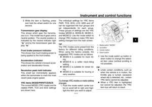 33
33 34
34 35
35 36
36 37
37 38
38 39
39 40
40 41
41 42
42 43
43 44
44 45
45 46
46 47
47 48
48 49
49 50
50 51
51 52
52 53
53 54
54 55
55 56
56 57
57 58
58 59
59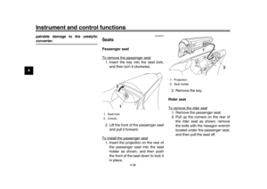 60
60 61
61 62
62 63
63 64
64 65
65 66
66 67
67 68
68 69
69 70
70 71
71 72
72 73
73 74
74 75
75 76
76 77
77 78
78 79
79 80
80 81
81 82
82 83
83 84
84 85
85 86
86 87
87 88
88 89
89 90
90 91
91 92
92 93
93 94
94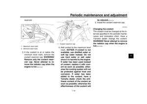 95
95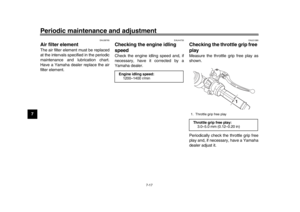 96
96 97
97 98
98 99
99 100
100 101
101 102
102 103
103 104
104 105
105 106
106 107
107 108
108 109
109 110
110 111
111 112
112 113
113 114
114 115
115 116
116 117
117 118
118 119
119 120
120 121
121 122
122 123
123 124
124 125
125 126
126 127
127 128
128 129
129
