Page 17 of 130
Description
2-3
123
4
5
6
7
8
9
10
11
12
EAU10431
Controls and instruments
12456 101112
3
7,8,9
1. Clutch lever (page 4-31)
2. Left handlebar switches (page 4-3)
3. ERS coupler (YZF-R1M) (page 4-41)
4. Main switch/steering lock (page 4-2)
5. Instrument panel (page 4-6, 4-8)
6. Front brake fluid reservoir (page 7-24)
7. Spring preload adjusting nut (YZF-R1) (page 4-41)
8. Rebound damping force adjusting bolt (YZF-R1)(page 4-41) 9. Compression damping force adjus
ting bolt (YZF-R1) (page 4-41)
10.Right handlebar switches (page 4-3)
11.Throttle grip (page 7-17)
12.Brake lever (page 4-32)
BX4-9-E1_1.book 3 ページ 2018年4月27日 金曜日 午後4時3分
Page 18 of 130
Yamaha Ride Control is a system that
incorporates numerous sensors and
controls to support an improved riding
experienc")
3-1
1
23
4
5
6
7
8
9
10
11
12
Special features
EAU66297
YRC (Yamaha Ride Control)Yamaha Ride Control is a system that
incorporates numerous sensors and
controls to support an improved riding
experience. The vehicle senses and
can react to forces along the longitudi-
nal (front-to-back), lateral (left-to-right),
and vertical (up-and-down) axes. Lean
angle and G-force accelerations are
also detected. This information is pro-
cessed multiple times a second and the
related physical systems are automati-
cally adjusted as necessary. The fol-
lowing functions represent individual
YRC items which can be turned on/off
or adjusted to suit various riders and
riding conditions. For setting details,
see pages 4-11 and 4-16.
WARNING
EWA18221
The Yamaha Ride Control (YRC) sys-
tem is not a substitute for the use of
proper riding techniques or the ex-
pertise of the operator. This system
cannot prevent loss of control
caused by rider errors such as trav-
eling faster than warranted by road
and traffic condition s, including lossof traction due to excessive speed
when entering turns, when acceler-
ating hard at a sharp lean angle, or
while braking, and it cannot prevent
front wheel slip or front wheel lift. As
with any motorcycle, always ride
within in your limits, be aware of sur-
rounding conditions, and ride ap-
propriately for those conditions.
Become thoroughly familiar with the
way the motorcycle handles with
various YRC settings before at-
tempting more advanced maneu-
vers.
PWR
The power delivery mode system con-
sists of four different control maps
which regulate throttle valve opening in
relation to the degree of throttle grip op-
eration, thus providing you with a selec-
tion of modes to fit your preferences
and the riding environment.
TCS
The traction control system helps main-
tain traction when accelerating. If sen-
sors detect that the rear wheel is
starting to slip (uncontrolled spinning),
the traction control system assists by
regulating engine power as needed un-
til traction is restored. The traction con-
trol system indicator/warning light
flashes to let the rider know that traction
control has engaged.
This traction control system automati-
1. PWR 1
2. PWR 2
3. PWR 3
4. PWR 4
5. Throttle valve opening
6. Throttle grip operation
5
64
3 2
1
BX4-9-E1_1.book 1 ページ 2018年4月27日 金曜日 午後4時3分
Page 19 of 130

Special features
3-2
1
234
5
6
7
8
9
10
11
12
cally adjusts accordin
g to the vehicle’s
lean angle. To maximize acceleration,
when the vehicle is upright a less
amount of traction control is applied.
When cornering, a greater amount of
traction control is applied.
TIP
The traction control system may
engage when the vehicle travels
over a bump.
You may notice slight changes in
engine and exhaust sounds when
the traction control or other YRC
systems engage.
When TCS is turned off, SCS,
LCS, and LIF are also turned offautomatically.
WARNING
EWA15432
The traction control system is not a
substitute for riding appropriately
for the conditions. Traction control
cannot prevent loss of traction due
to excessive speed when entering
turns, when accelerating hard at a
sharp lean angle, or while braking,
and cannot prevent front wheel slip-
ping. As with any motorcycle, ap-
proach surfaces that may be
slippery with caution and avoid es-pecially slippery surfaces.
When the key is turned to “ON”, the
traction control system automatically
turns on. The traction control system
can be turned on or off manually only
when the key is in the “ON” position and
the motorcycle is stopped.TIPTurn the traction control system off to
help free the rear wheel if the motorcy-
cle gets stuck in mud, sand, or othersoft surfaces.
NOTICE
ECA16801
Use only the specified tires. (See
page 7-18.) Using different sized
tires will prevent the traction control
system from controlling tire rotationaccurately.
SCS
The slide control system regulates en-
gine power output when a sideward
slide is detected in the rear wheel. It ad-
justs power output based on data from
the IMU. This system supports the TCS
to contribute to a smoother ride.
LCS
The launch control system helps the
rider achieve smooth and swift
launches from the starting grid. It
keeps engine speed from rising above
8,000 r/min even when the throttle
grip is fully turned. The LCS regulates
engine power output in conjunction
with the TCS and LIF systems for op-
timal traction and reduced wheel lift.
TCS
BX4-9-E1_1.book 2 ページ 2018年4月27日 金曜日 午後4時3分
Page 20 of 130

Special features
3-3
1
23
4
5
6
7
8
9
10
11
12
NOTICE
ECA22950
Even when using LCS, the clutch le-
ver must be released gradually toavoid clutch damage.TIPLCS is intended for track use only.
QSS
The quick shift system allows for clutch
lever-less, electronically-assisted shift-
ing. When the sensor on the shift rod
detects the appropriate motion in the
shift pedal, engine power output is mo-
mentarily adjusted to allow for the gear
change to occur.
QSS does not operate when the clutch
lever is pulled, therefore normal shifting
can be done even when QSS is set to
on. Check the QS indicator for current
status and usability information. Upshifting conditions
Vehicle speed of at least 20 km/h
(12 mi/h)
Engine speed of at least 2200 r/min
Accelerating (open throttle)
Downshifting conditions
Vehicle speed of at least 20 km/h
(12 mi/h)
Engine speed of at least 2000 r/min
Engine speed sufficiently away
from red zone
Decelerating and throttle ful-
ly-closed
TIP
QS and QS can be individu-
ally set.
Shifting into or out of neutral mustbe done using the clutch lever.
LIF
The lift control system reduces the rate
at which the front wheel will continue to
rise during extreme acceleration, such
as during starts or out-of-corner exits.
When front-wheel lift is detected, en-
gine power is regulated to slow front-wheel lift while still providing good
acceleration.
ERS (YZF-R1M)
The electronic racing suspension by
Öhlins features OBTi (objective-based
tuning interface) for simplified, situa-
tion-focused setting changes of the au-
tomatic suspension control modes. In
addition, there are manual modes
which offer a finely-tuneable traditional
suspension set-up. The ERS system is
controlled by the SCU which can adjust
the front and rear suspension’s com-
pression stroke and rebound stroke
damping forces independently. The au-
tomatic modes will adjust suspension
damping forces based on running con-
ditions.
QSS usability Indicator Situation
Upshifting OK Accelerating
Downshifting
OK Decelerating
QSS cannot be
used Stopped
QSS turned off Turned off
BX4-9-E1_1.book 3 ページ 2018年4月27日 金曜日 午後4時3分
Page 21 of 130
Special features
3-4
1
234
5
6
7
8
9
10
11
12
EAU66312
GlossaryABS - Anti-lock Brake System
ABS ECU - Anti-lock Brake System
Electronic Control Unit
CCU - Communication Control Unit
ECU - Engine Control Unit
ERS - Electronic Racing Suspension
GPS - Global Positioning System
IMU - Inertial Measurement Unit
LCS - Launch Control System
LIF - Lift Control System
PWR - Power delivery mode
QS - Quick Shift
QSS - Quick Shift System
SC - Stability Control
SCS - Slide Control System
SCU - Suspension Control Unit
TCS - Traction Control System
UBS - Unified Brake System
YRC - Yamaha Ride Control
BX4-9-E1_1.book 4 ページ 2018年4月27日 金曜日 午後4時3分
Page 22 of 130
Special features
3-5
1
23
4
5
6
7
8
9
10
11
12
EAU66911
YRC functions visual guide1. Start
2. Acceleration
3. Braking
4. Apex
5. Exit 6. Straightaway
BX4-9-E1_1.book 5 ページ 2018年4月27日 金曜日 午後4時3分
Page 23 of 130

4-1
1
2
345
6
7
8
9
10
11
12
Instrument and control functions
EAU10978
Immobilizer systemThis vehicle is equipped with an immo-
bilizer system to help prevent theft by
re-registering codes in the standard
keys. This system consists of the fol-
lowing:
a code re-registering key (with a
red bow)
two standard keys (with a black
bow) that can be re-registered with
new codes
a transponder (which is installed in
the code re-registering key)
an immobilizer unit
an ECU
an immobilizer system indicator light (See page 4-7.)
The key with the red bow is used to reg-
ister codes in each standard key. Since
re-registering is a difficult process, take
the vehicle along with all three keys to
a Yamaha dealer to have them re-reg-
istered. Do not use the key with the red
bow for driving. It should only be used
for re-registering the standard keys. Al-
ways use a standard key for driving.
NOTICE
ECA11822
DO NOT LOSE THE CODE
RE-REGISTERING KEY! CON-
TACT YOUR DEALER IMMEDI-
ATELY IF IT IS LOST! If the code
re-registering key is lost, regis-
tering new codes in the stan-
dard keys is impossible. The
standard keys can still be used
to start the vehicle, however if
code re-registering is required
(i.e., if a new standard key is
made or all keys are lost) the en-
tire immobilizer system must be
replaced. Therefore, it is highly
recommended to use either
standard key and keep the code
re-registering key in a safe place.
Do not submerse any key in wa-
ter.
Do not expose any key to exces-
sively high temperatures.
Do not place any key close to
magnets (this includes, but not
limited to, products such as
speakers, etc.).
Do not place items that transmit
electrical signals close to any
key.
Do not place heavy items on any
key.
Do not grind any key or alter its
shape.
Do not disassemble the plastic
part of any key.
Do not put two keys of any im-
mobilizer system on the same
key ring.
Keep the standard keys as well
as keys of other immobilizer
systems away from this vehi-
cle’s code re-registering key.
Keep other immobilizer system
keys away from the main switch
as they may cause signal inter-
1. Code re-registering key (red bow)
2. Standard keys (black bow)
BX4-9-E1_1.book 1 ページ 2018年4月27日 金曜日 午後4時3分
Page 24 of 130

Instrument and control functions
4-2
1
2
34
5
6
7
8
9
10
11
12
ference.
EAU10474
Main switch/steering lockThe main switch/steering lock controls
the ignition and lighting systems, and is
used to lock the steering. The various
positions are described below.TIPBe sure to use the standard key (black
bow) for regular use of the vehicle. To
minimize the risk of losing the code
re-registering key (red bow), keep it in a
safe place and only use it for codere-registering.
EAU10552
ON
All electrical circuits are supplied with
power. The meter lighting, taillight, li- cense plate light and auxiliary lights
come on, and the engine can be start-
ed. The key cannot be removed.
TIPThe headlights come on automatically
when the engine is started and stay on
until the key is turned to “OFF”, even ifthe engine stalls.
EAU10662
OFF
All electrical systems are off. The key
can be removed.
WARNING
EWA10062
Never turn the key to “OFF” or
“LOCK” while the vehicle is moving.
Otherwise the electrical systems will
be switched off, which may result inloss of control or an accident.
EAU1068B
LOCK
The steering is locked and all electrical
systems are off. The key can be re-
moved.
P
ON
OFF
LOCK
BX4-9-E1_1.book 2 ページ 2018年4月27日 金曜日 午後4時3分
 1
1 2
2 3
3 4
4 5
5 6
6 7
7 8
8 9
9 10
10 11
11 12
12 13
13 14
14 15
15 16
16 17
17 18
18 19
19 20
20 21
21 22
22 23
23 24
24 25
25 26
26 27
27 28
28 29
29 30
30 31
31 32
32 33
33 34
34 35
35 36
36 37
37 38
38 39
39 40
40 41
41 42
42 43
43 44
44 45
45 46
46 47
47 48
48 49
49 50
50 51
51 52
52 53
53 54
54 55
55 56
56 57
57 58
58 59
59 60
60 61
61 62
62 63
63 64
64 65
65 66
66 67
67 68
68 69
69 70
70 71
71 72
72 73
73 74
74 75
75 76
76 77
77 78
78 79
79 80
80 81
81 82
82 83
83 84
84 85
85 86
86 87
87 88
88 89
89 90
90 91
91 92
92 93
93 94
94 95
95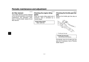 96
96 97
97 98
98 99
99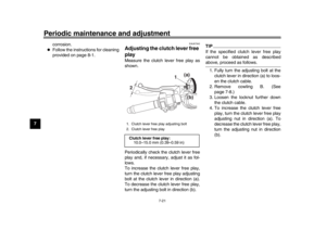 100
100 101
101 102
102 103
103 104
104 105
105 106
106 107
107 108
108 109
109 110
110 111
111 112
112 113
113 114
114 115
115 116
116 117
117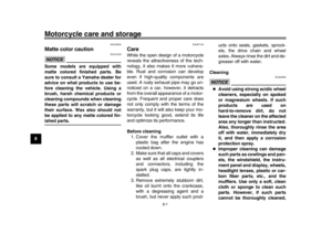 118
118 119
119 120
120 121
121 122
122 123
123 124
124 125
125 126
126 127
127 128
128 129
129
2. Left handlebar switches (page 4-3)
3. ERS coupler (YZF-R1M) (page 4-41)
4")

