Page 57 of 130

Instrument and control functions
4-35
1
2
345
6
7
8
9
10
11
12
less the key is in the lock. In addition,
the key cannot be removed if the cap is
not properly closed and locked.
WARNING
EWA11092
Make sure that the fuel tank cap is
properly closed after filling fuel.Leaking fuel is a fire hazard.
EAU13222
FuelMake sure there is sufficient gasoline in
the tank.
WARNING
EWA10882
Gasoline and gasoline vapors are
extremely flammable. To avoid fires
and explosions and to reduce the
risk of injury when refueling, followthese instructions.
1. Before refueling, turn off the en- gine and be sure that no one is sit-
ting on the vehicle. Never refuel
while smoking, or while in the vi-
cinity of sparks, open flames, or
other sources of ignition such as
the pilot lights of water heaters and
clothes dryers.
2. Do not overfill the fuel tank. When refueling, be sure to insert the
pump nozzle into the fuel tank filler
hole. Stop filling when the fuel
reaches the bottom of the filler
tube. Because fuel expands when
it heats up, heat from the engine or
the sun can cause fuel to spill out
of the fuel tank. 3. Wipe up any spilled fuel immedi-
ately. NOTICE: Immediately wipe
off spilled fuel with a clean, dry,
soft cloth, since fuel may deteri-
orate painted surfaces or plastic
parts.
[ECA10072]
4. Be sure to securely close the fuel tank cap.
WARNING
EWA15152
Gasoline is poisonous and can
cause injury or death. Handle gaso-
line with care. Never siphon gaso-
line by mouth. If you should swallow
some gasoline or inhale a lot of gas-
oline vapor, or get some gasoline in1. Fuel tank filler tube
2. Maximum fuel level
1
2
BX4-9-E1_1.book 35 ページ 2018年4月27日 金曜日 午後4時3分
Page 58 of 130

Instrument and control functions
4-36
1
2
34
5
6
7
8
9
10
11
12 your eyes, see your doctor immedi-
ately. If gasoline spills on your skin,
wash with soap and water. If gaso-
line spills on your clothing, change
your clothes.
EAU75320
NOTICE
ECA11401
Use only unleaded gasoline. The use
of leaded gasoline will cause severe
damage to internal engine parts,
such as the valves and piston rings,as well as to the exhaust system.
TIP
This mark identifies the recom-
mended fuel for this vehicle as
specified by European regulation
(EN228).
Check that gasoline nozzle has thesame identifier when fueling.
Your Yamaha engine has been de-
signed to use premium unleaded gaso-
line with a research octane number of
95 or higher. If knocking (or pinging) oc-
curs, use a gasoline of a different
brand. Use of unleaded fuel will extend
spark plug life and reduce maintenance
costs.
Gasohol
There are two types of gasohol: gaso- hol containing ethanol and that contain-
ing methanol. Gasohol containing
ethanol can be used if the ethanol con-
tent does not exceed 10% (E10). Gas-
ohol containing methanol is not
recommended by Yamaha because it
can cause damage to the fuel system
or vehicle performance problems.
Recommended fuel:
Premium unleaded gasoline (Gaso-
hol [E10] acceptable)
Fuel tank capacity: 17 L (4.5 US gal, 3.7 Imp.gal)
Fuel reserve amount (when the fuel
level warning light comes on):
3.0 L (0.79 US gal, 0.66 Imp.gal)
E5
E10
BX4-9-E1_1.book 36 ページ 2018年4月27日 金曜日 午後4時3分
Page 59 of 130

Instrument and control functions
4-37
1
2
345
6
7
8
9
10
11
12
EAU80200
Fuel tank overflow hoseBefore operating the vehicle:
Check the fuel tank overflow hose
connection.
Check the fuel tank overflow hose
for cracks or damage, and replace
it if necessary.
Make sure that the end of the fuel
tank overflow hose is not blocked,
and clean it if necessary.
Make sure that the end of the fuel
tank overflow hos e is positioned as
shown.
TIPSee page 7-12 for canister information.
EAU13434
Catalytic converterThis model is equipped with a catalytic
converter in the exhaust system.
WARNING
EWA10863
The exhaust system is hot after op-
eration. To prevent a fire hazard or
burns:
Do not park the vehicle near
possible fire hazards such as
grass or other materials that
easily burn.
Park the vehicle in a place
where pedestrians or children
are not likely to touch the hot
exhaust system.
Make sure that the exhaust sys-
tem has cooled down before do-
ing any maintenance work.
Do not allow the engine to idle
more than a few minutes. Long
idling can cause a build-up ofheat.
NOTICE
ECA10702
Use only unleaded gasoline. The use
of leaded gasoline will cause unre-
1. Clamp
2. Paint mark
3. Fuel tank overflow hose
1
2
3
BX4-9-E1_1.book 37 ページ 2018年4月27日 金曜日 午後4時3分
Page 60 of 130
Instrument and control functions
4-38
1
2
34
5
6
7
8
9
10
11
12 pairable damage to the catalytic
converter.
EAU66570
SeatsPassenger seat
To remove the passenger seat1. Insert the key into the seat lock,
and then turn it clockwise.
2. Lift the front of the passenger seat and pull it forward.
To install the passenger seat1. Insert the projection on the rear of the passenger seat into the seat
holder as shown, and then push
the front of the seat down to lock it
in place. 2. Remove the key.
Rider seat
To remove the rider seat
1. Remove the passenger seat.
2. Pull up the corners on the rear of the rider seat as shown, remove
the bolts with the hexagon wrench
located under the passenger seat,
and then pull the seat off.
1. Seat lock
2. Unlock.
12
1. Projection
2. Seat holder
1
2
BX4-9-E1_1.book 38 ページ 2018年4月27日 金曜日 午後4時3分
Page 61 of 130

Instrument and control functions
4-39
1
2
345
6
7
8
9
10
11
12
To install the rider seat
1. Insert the projections into the seat
holders as shown, then place the
seat in the original position. 2. Install the bolts with the hexagon
wrench.
3. Insert the hexagon wrench back into its holder.
4. Install the passenger seat.
TIPMake sure that the seats are properlysecured before riding.
EAU67156
CCU (for equipped models)The CCU (communication control unit)
connects to the vehicle’s CAN (control-
ler area network) and has a GPS re-
ceiver to enable the recording of
vehicle and riding data (see “Logging”
on page 4-22). Logging data and YRC
setting data can be accessed when a
smartphone or tablet is connected to
the CCU wireless network.TIPFrom the Google© or Apple© applica-
tion store, download the “Y-TRAC” ap-
plication to make use of the logging
data and the “YRC Setting” applicationto remotely adjust the YRC settings.
To connect to the CCU wireless net-work1. Remove the screws, move the GPS receiver, and then remove
the seat cover as shown.
1. Bolt
1. Hexagon wrench
1
1
1. Projection
2. Seat holder
1
2
BX4-9-E1_1.book 39 ページ 2018年4月27日 金曜日 午後4時3分
Page 62 of 130

Instrument and control functions
4-40
1
2
34
5
6
7
8
9
10
11
12 2. Note down the CCU serial num-
ber.
3. Turn the key to “ON” and approach the vehicle with a wireless capable smartphone or tablet.
4. Connect to the wireless network “YAMAHA MOTOR CCU” by in-
putting the CCU serial number as
the password.
5. Install the seat cover and GPS re- ceiver to the original position, and
then install the screws.
TIPSince all CCU-equipped models put out
a similarly named wireless network,
have only one vehicle turned on at atime to avoid confusion.
EAU66920
Document storageA document storage space is located
under panel C. (See page 7-8.)
When storing the owner’s manual or
vehicle registration and insurance doc-
uments in the document storage space,
be sure to wrap them in a plastic bag so
that they will not get wet. When wash-
ing the vehicle, avoid letting water enter
the document storage space.NOTICE
ECA22540
Do not place heat-sensitive items in
the document storage space. This
space can get hot when the engine
is running or when the vehicle is in
1. Screw
2. Seat cover
3. GPS receiver
1. CCU serial number1
1
2
3
1
1. Document storage space
2. Panel C
1
2
BX4-9-E1_1.book 40 ページ 2018年4月27日 金曜日 午後4時3分
Page 63 of 130

Instrument and control functions
4-41
1
2
345
6
7
8
9
10
11
12
direct sunlight.
EAU47261
Rear view mirrorsThe rear view mirrors of this vehicle can
be folded forward for parking in narrow
spaces. Fold the mirrors back to their
original position before riding.
WARNING
EWA14372
Be sure to fold the rear view mirrors
back to their original position beforeriding.
EAU66474
Adjusting the front forkNOTICE
ECA22471
Use extra care to avoid scratch-
ing the gold-anodized finish
when making suspension ad-
justments.
To avoid damaging the suspen-
sion’s internal mechanisms, do
not attempt to turn beyond themaximum or minimum settings.
For YZF-R1
This model is equipped with adjustable
suspension. The spring preload, re-
bound damping force, and compres-
sion damping force of each leg can be
adjusted.WARNING
EWA10181
Always adjust both fork legs equal-
ly, otherwise poor handling and lossof stability may result.
Spring preload
To increase the spring preload and
thereby harden the suspension, turn
1. Riding position
2. Parking position11
2 22
2
BX4-9-E1_1.book 41 ページ 2018年4月27日 金曜日 午後4時3分
Page 64 of 130
. To decrease the spring preload
and thereby soften the suspension,
turn the adjusting")
Instrument and control functions
4-42
1
2
34
5
6
7
8
9
10
11
12 the adjusting nut on each fork in direc-
tion (a). To decrease the spring preload
and thereby soften the suspension,
turn the adjusting nut on each fork in di-
rection (b).
Rebound damping force
To increase the rebound damping force
and thereby harden the rebound damp- ing, turn the adjusting bolt on each fork
leg in direction (a). To decrease the re-
bound damping force and thereby soft-
en the rebound damping, turn the
adjusting bolt on each fork leg in direc-
tion (b).
Compression damping force
To increase the compression dampingforce and thereby harden the compres-
sion damping, turn the adjusting bolt on
each fork leg in direction (a). To de-
crease the compression damping force
and thereby soften the compression
damping, turn the adjusting bolt on
each fork leg in direction (b).
1. Spring preload adjusting nutSpring preload setting:
Minimum (soft):
0 turn(s) in direction (a)*
Standard: 9 turn(s) in direction (a)*
Maximum (hard): 15 turn(s) in direction (a)*
* With the adjusting nut fully turned in
direction (b)
1
(a) (b)
1. Rebound damping force adjusting boltRebound damping setting:
Minimum (soft):
14 click(s) in direction (b)*
Standard: 7 click(s) in direction (b)*
Maximum (hard): 1 click(s) in direction (b)*
* With the adjusting bolt fully turned in
direction (a)
1
(a) (b)
1. Compression damping force adjusting boltCompression damping setting:
Minimum (soft):
23 click(s) in direction (b)*
Standard: 17 click(s) in direction (b)*
Maximum (hard): 1 click(s) in direction (b)*
* With the adjusting bolt fully turned in
direction (a)
1
(a) (b)
BX4-9-E1_1.book 42 ページ 2018年4月27日 金曜日 午後4時3分
 1
1 2
2 3
3 4
4 5
5 6
6 7
7 8
8 9
9 10
10 11
11 12
12 13
13 14
14 15
15 16
16 17
17 18
18 19
19 20
20 21
21 22
22 23
23 24
24 25
25 26
26 27
27 28
28 29
29 30
30 31
31 32
32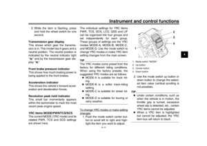 33
33 34
34 35
35 36
36 37
37 38
38 39
39 40
40 41
41 42
42 43
43 44
44 45
45 46
46 47
47 48
48 49
49 50
50 51
51 52
52 53
53 54
54 55
55 56
56 57
57 58
58 59
59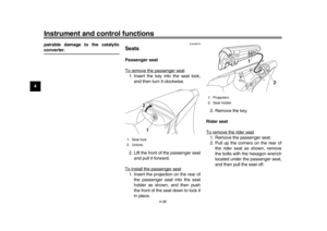 60
60 61
61 62
62 63
63 64
64 65
65 66
66 67
67 68
68 69
69 70
70 71
71 72
72 73
73 74
74 75
75 76
76 77
77 78
78 79
79 80
80 81
81 82
82 83
83 84
84 85
85 86
86 87
87 88
88 89
89 90
90 91
91 92
92 93
93 94
94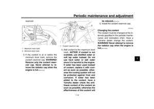 95
95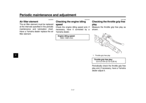 96
96 97
97 98
98 99
99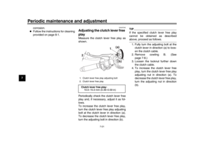 100
100 101
101 102
102 103
103 104
104 105
105 106
106 107
107 108
108 109
109 110
110 111
111 112
112 113
113 114
114 115
115 116
116 117
117 118
118 119
119 120
120 121
121 122
122 123
123 124
124 125
125 126
126 127
127 128
128 129
129