Page 17 of 180

WARNING!
A loose head restraint thrown forward in a
collision or hard stop could cause serious
injury or death to occupants of the vehicle.
Always securely stow removed head re-
straints in a location outside the occupant
compartment.
Front Removal
To remove the head restraint, raise it as far as
it can go then push the release button and the
adjustment button at the base of each post
while pulling the head restraint up. To rein-
stall the head restraint, put the head restraint
posts into the holes and push downward.
Then adjust the head restraint to the appro-
priate height.
WARNING!
• A loose head restraint thrown forward ina collision or hard stop could cause se-
rious injury or death to occupants of the
vehicle. Always securely stow removed
WARNING!
head restraints in a location outside the
occupant compartment.
• ALL the head restraints MUST be rein-
stalled in the vehicle to properly protect
the occupants. Follow the re-installation
instructions above prior to operating the
vehicle or occupying a seat.
Rear Removal
Outboard Head Restraints
The outboard head restraints can be removed
by pushing the release buttons, located at the
base of the head restraint and pull upward on
the whole assembly. To reinstall the head
restraint, put the head restraint posts into the
holes and push downward. Then adjust it to
the appropriate height. Center Head Restraint
To remove the head restraint, push the re-
lease button and adjustment button while
pulling upward on the whole assembly and
raise it as far as it can go. To reinstall the
headrest, put the headrest posts into the
holes while pushing the release button and
adjustment button. Then adjust it to the
appropriate height.
Outboard Head Restraint Release Buttons
15
Page 18 of 180

WARNING!
• A loose head restraint thrown forward ina collision or hard stop could cause
serious injury or death to occupants of
the vehicle. Always securely stow re-
moved head restraints in a location out-
side the occupant compartment.
• ALL the head restraints MUST be rein-
stalled in the vehicle to properly protect
the occupants. Follow the re-installation
instructions above prior to operating the
vehicle or occupying a seat.
STEERING WHEEL
Tilt/Telescoping Steering Column
This feature allows you to tilt the steering
column upward or downward. It also allows
you to lengthen or shorten the steering col-
umn. The tilt/telescoping control handle is
located on the steering column, below the
turn signal lever. To unlock the steering column, push the
control lever downward. To tilt the steering
column, move the steering wheel upward or
downward as desired. To lengthen or shorten
the steering column, pull the steering wheel
outward or push it inward as desired. To lock
the steering column in position, pull the
control lever up until fully engaged.
WARNING!
Do not adjust the steering column while
driving. Adjusting the steering column
while driving or driving with the steering
column unlocked, could cause the driver
to lose control of the vehicle. Failure to
follow this warning may result in serious
injury or death.
EXTERIOR LIGHTS
Multifunction Lever
The multifunction lever, located on the left
side of the steering wheel, controls the opera-
tion of the headlights, high beams, parking
lights, passing light and turn signals.
NOTE:
The external lights can only be turned on with
the ignition in the ON/RUN position.Tilt/Telescoping Lever
GETTING TO KNOW YOUR VEHICLE
16
Page 19 of 180

Headlights
Rotate the end of the multifunction lever
upward to the first detent for headlight opera-
tion.
NOTE:
When the headlights are turned on, the Day-
time Running Lights, (if previously set
through the menu) will be deactivated.
High Beams
With the low beams activated, pull the mul-
tifunction lever towards the steering wheel to
turn on the high beams. A high beam symbolwill illuminate in the cluster to indicate the
high beams are on. Pull the multifunction
lever a second time to switch the headlights
back to low beam.
Parking Lights
To turn on the parking lights, remove the key
or turn the ignition to OFF/LOCK position and
turn on the headlights.
Follow Me Home/Headlight Delay
When this feature is selected, the driver can
choose to have the headlights remain on for a
preset period of time after the engine is
turned OFF.
Activation
Remove the key or turn the ignition to the
STOP (OFF/LOCK) position, and pull the mul-
tifunction lever toward the steering wheel
within two minutes. Each time the lever is
pulled, the activation of the lights will be
extended by 30 seconds. The activation of
the lights can be extended to a maximum of
210 seconds.
Deactivation
Pull the multifunction lever toward the steer-
ing wheel and hold it for more than two
seconds.
Turn Signals
Move the multifunction lever up or down and
the arrows on each side of the instrument
cluster flash to show proper operation of the
front and rear turn signal lights.
NOTE:
If either light remains on and does not flash,
or there is a very fast flash rate, check for a
defective outside light bulb. If an indicator
fails to light when the lever is moved, it would
suggest that the indicator bulb is defective.
Lane Change Assist
Tap the lever up or down once, without mov-
ing beyond the detent, and the turn signal
(right or left) will flash five times then auto-
matically turn off.
Turn Signal Headlight Lever
1 — Headlights
2 — Turn Signals
3 — High Beams
17
Page 20 of 180

INTERIOR LIGHTS
The map lights and dome lights are mounted
between the sun visors on the overhead con-
sole. Each light is turned on by pushing the
corresponding switch.
In auto-mode, the passenger and cargo area
lights will come on automatically when you
open the sliding doors and the rear wing
doors. The lights turn off when you close the
doors.
The lights will fade to off after approximately
30 seconds, or they will immediately fade to
off once the ignition switch is turned to
ON/RUN from the OFF position.
WIPERS AND WASHERS
The windshield wiper/washer lever is located
on the right side of the steering column.
NOTE:
The windshield wipers/washers will only op-
erate with the ignition in the ON/RUN posi-
tion.
Front Wiper Operation
There are five different modes of operation
for the front windshield wipers. The wind-
shield wiper lever can be moved in several
positions to access these modes.
Windshield Wiper Off
This is the normal position of the wiper lever: O.
Low Speed
Rotate the end of the lever upward to the
second detent. The wipers will operate at low
speed.
High Speed
Rotate the end of the lever upward to the
third detent. The wipers will operate at high
speed.
Intermittent Wiper System
Rotate the end of the lever upward to the first
detent. The wipers will operate at intermit-
tent speed. When the vehicle's speed in-
creases, the time between the wipes will
decrease.
Windshield Washers
Pull the windshield wiper/washer lever to-
ward the steering wheel to activate the wash-
ers. The wipers will activate automatically for
three cycles after the lever is released.
Wiper Washer Lever
1 — Pull Front Washer
2 — Push Rear Washer
3 — Intermittent, Low And High Speed
Front Wiper
4 — Mist
GETTING TO KNOW YOUR VEHICLE
18
Page 21 of 180

CAUTION!
• Turn the windshield wipers off whendriving through an automatic car wash.
Damage to the windshield wipers may
result if the wiper control is left in any
position other than off.
• In cold weather, always turn off the wiper
switch and allow the wipers to return to
the park position before turning off the
engine. If the wiper switch is left on and
the wipers freeze to the windshield,
damage to the wiper motor may occur
when the vehicle is restarted.
• Always remove any buildup of snow that
prevents the windshield wiper blades
from returning to the off position. If the
windshield wiper control is turned off
and the blades cannot return to the off
position, damage to the wiper motor may
occur.
Manual High Speed/Mist
Push the lever upward from the off position.
The wipers will operate at high speed to clear
off road mist or spray from a passing vehicle.
This operation will continue until the lever is
released. When the lever is released, the
wipers will return to the off position and
automatically shut off.
Rear Wiper Operation
Rear Windshield Wiper Operation
Rotate the windshield wiper lever center ring
upwards to operate the rear window wiper as
follows:
• In intermittent mode when the front win-
dow wiper is not operating.
• In synchronous mode (at half the speed of the front window wiper) when the front
window wiper is operating. • In continuous mode while vehicle is in
REVERSE.
With the windshield wipers on, and REVERSE
gear engaged, rear window wiping will be
continuous in the same way.
Rear Windshield Washer Operation
Pushing the windshield wiper lever forward
activates the rear window washer. Keep the
windshield wiper lever pushed for more than
quarter a second to activate the rear window
wiper as well. Releasing the windshield wiper
lever will activate the smart washing func-
tion, as described for the windshield wipers.
The function stops when the windshield
wiper lever is released.
19
Page 22 of 180
CLIMATE CONTROLS
Manual Climate Control Overview
Manual Climate Controls
1 — A/C Button
2 — Air Recirculation Button
3 — Rear Window Defroster/Heated Mirrors Button4 — Mode Control Knob
5 — Blower Control Knob
6 — Temperature Control Knob
GETTING TO KNOW YOUR VEHICLE
20
Page 23 of 180
. A LED will illuminate when the A/C system is engaged. The
A/C can be deselected")
Manual Climate Control Descriptions
IconDescription
A/C Button
Push the A/C button to engage the Air Conditioning (A/C). A LED will illuminate when the A/C system is engaged. The
A/C can be deselected manually without disturbing the mode control selection.
Recirculation Button
Press and release this button to change the system between recirculation mode and outside air mode. Recirculation can
be used when outside conditions such as smoke, odors, dust, or high humidity are present.
NOTE:
• Continuous use of the Recirculation mode may make the inside air stuffy and window fogging may occur. Extended
use of this mode is not recommended.
• The use of the Recirculation mode in cold or damp weather could cause windows to fog on the inside, because of
moisture buildup inside the vehicle. Select the outside air position for maximum defogging.
• Recirculation can be used in all modes except for Defrost.
Front Defrost
Use Defrost mode with maximum temperature settings for best windshield and side window defrosting and defog-
ging. Turn the knob to the Front Defrost position. Air comes from the windshield and side window demist outlets.
Rear Defrost Button
Push and release the Rear Defrost Control button to turn ON the rear window defroster and the heated outside mir-
rors (if equipped). An indicator will illuminate when the rear window defroster is ON. The rear window defroster auto-
matically turns OFF after 20 minutes.
21
Page 24 of 180

IconDescription
Temperature Control
Use this control to regulate the temperature of the air inside the passenger compartment. Rotating the knob counter-
clockwise, from top center into the blue area of the scale, indicates cooler temperatures. Rotating the knob clockwise,
into the red area, indicates warmer temperatures.
Blower Control
There are four blower speeds. Use this control to regulate the amount of air forced through the system in any mode you
select. The blower speed increases as you move the control clockwise from the OFF position.
Modes Control
Push the button in the center of the knob to change the airflow distribution mode. The airflow distribution mode can be
adjusted so air comes from the instrument panel outlets, floor outlets, defrost outlets and demist outlets. The Mode set-
tings are as follows:
Panel Mode
Panel Mode
Air comes from the outlets in the instrument panel. Each of these outlets can be individually adjusted to direct the flow
of air. The air vanes of the center outlets and outboard outlets can be moved up and down or side to side to regulate
airflow direction. There is a shut off wheel located below the air vanes to shut off or adjust the amount of airflow from
these outlets.
Bi-Level Mode
Bi-Level Mode
Air comes from the instrument panel outlets and floor outlets. A slight amount of air is directed through the defrost and
side window demister outlets.
NOTE:
Bi-Level mode is designed under comfort conditions to provide cooler air out of the panel outlets and warmer air from
the floor outlets.GETTING TO KNOW YOUR VEHICLE
22
 1
1 2
2 3
3 4
4 5
5 6
6 7
7 8
8 9
9 10
10 11
11 12
12 13
13 14
14 15
15 16
16 17
17 18
18 19
19 20
20 21
21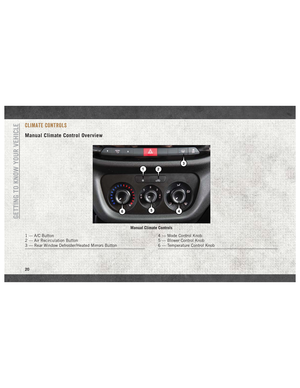 22
22 23
23 24
24 25
25 26
26 27
27 28
28 29
29 30
30 31
31 32
32 33
33 34
34 35
35 36
36 37
37 38
38 39
39 40
40 41
41 42
42 43
43 44
44 45
45 46
46 47
47 48
48 49
49 50
50 51
51 52
52 53
53 54
54 55
55 56
56 57
57 58
58 59
59 60
60 61
61 62
62 63
63 64
64 65
65 66
66 67
67 68
68 69
69 70
70 71
71 72
72 73
73 74
74 75
75 76
76 77
77 78
78 79
79 80
80 81
81 82
82 83
83 84
84 85
85 86
86 87
87 88
88 89
89 90
90 91
91 92
92 93
93 94
94 95
95 96
96 97
97 98
98 99
99 100
100 101
101 102
102 103
103 104
104 105
105 106
106 107
107 108
108 109
109 110
110 111
111 112
112 113
113 114
114 115
115 116
116 117
117 118
118 119
119 120
120 121
121 122
122 123
123 124
124 125
125 126
126 127
127 128
128 129
129 130
130 131
131 132
132 133
133 134
134 135
135 136
136 137
137 138
138 139
139 140
140 141
141 142
142 143
143 144
144 145
145 146
146 147
147 148
148 149
149 150
150 151
151 152
152 153
153 154
154 155
155 156
156 157
157 158
158 159
159 160
160 161
161 162
162 163
163 164
164 165
165 166
166 167
167 168
168 169
169 170
170 171
171 172
172 173
173 174
174 175
175 176
176 177
177 178
178 179
179